Table of Contents
Advertisement
Quick Links
Advertisement
Table of Contents

Subscribe to Our Youtube Channel
Related Manuals for MAYSER SG-RS 309-2


Summary of Contents for MAYSER SG-RS 309-2
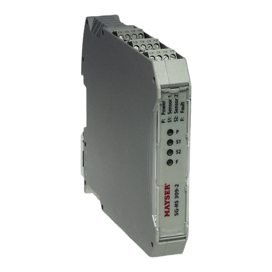
- Page 1 Innovative by tradition. Control unit SG-RS 309-2 EN | Operating instructions Version 1 1006747 SG-RS 309-2 24 to 36 V DC Mayser GmbH & Co. KG Örlinger Strasse 1–3 89073 Ulm GERMANY Tel.: +49 731 2061-0 Fax: +49 731 2061-222 E-mail: info.ulm@mayser.com Website: www.mayser.com...
- Page 2 Offenders will be held liable for the payment of damages. All rights reserved in the event of the grant of a patent, utility model or design. © Mayser Ulm 2022 121022 v1.02-RiA Operating instructions SG-RS 309-2 Page 2/23...
-
Page 3: Table Of Contents
Protective device activated ............................. 17 Correlations ..................................18 Decommissioning ................................18 Recommissioning ................................18 Maintenance and cleaning ..............................19 Maintenance ..................................19 Cleaning ....................................19 Troubleshooting and remedies ............................19 Replacement parts ................................21 Disposal ....................................21 Technical data ..................................22 121022 v1.02-RiA Operating instructions SG-RS 309-2 Page 3/23... -
Page 4: About These Instructions
About these instructions About these instructions These instructions are part of the product. Mayser accepts no responsibility or warranty claims for damage and consequen- tial damage due to failure to observe the instructions. Validity These instructions are only valid for the products specified on the title page. -
Page 5: Safety
Ä Do not use in ATEX zones Do not use the control unit in potentially explosive environments (ATEX). The control unit is not authorised for use in these zones. 121022 v1.02-RiA Operating instructions SG-RS 309-2 Page 5/23... -
Page 6: Residual Dangers
Make sure you wire the unit directly in the control circuit or that two channels continue to be used in the downstream control. Residual dangers There are no known residual dangers associated with this product. 121022 v1.02-RiA Operating instructions SG-RS 309-2 Page 6/23... -
Page 7: Parts Supplied
Semiconductor output OSSD 1.2 Signal output Monitoring circuit 2 (sensor 2) Semiconductor output OSSD 2.1 Semiconductor output OSSD 2.2 Signal output 11, 14; 31, 34 Without function 21, 24; 41, 44 Without function 121022 v1.02-RiA Operating instructions SG-RS 309-2 Page 7/23... -
Page 8: Leds Information
HIGH. The yellow LED “S2” is lit up. If sensor 1 and sensor 2 are activat- ed, then the OSSDs from monitoring circuit 1 and monitoring circuit 2 are in OFF state, signal outputs M1 and M2 are HIGH. The yellow LEDs “S1” and “S2” are lit 121022 v1.02-RiA Operating instructions SG-RS 309-2 Page 8/23... -
Page 9: Reset
No reset will take place if the pulse duration is shorter than the minimum permit- ted or if the pulse voltage is incorrect. If the max. pulse duration is exceeded, the control unit changes to the “Fault / Sys- tem error” mode (see Troubleshooting and remedies). 121022 v1.02-RiA Operating instructions SG-RS 309-2 Page 9/23... -
Page 10: Manual Reset
If the actuation period is shorter than the minimum permitted, no reset will take place. If the max. actuation period is exceeded, the control unit changes to the “Fault / System error” mode (see Troubleshooting and remedies). Reset pulse button Reset OSSD Fault 121022 v1.02-RiA Operating instructions SG-RS 309-2 Page 10/23... -
Page 11: Installation
If the control unit overheats as a result of external heat, operation of the pro- tective device may be impaired or it may fail completely. It is absolutely essential to ensure sufficient clearance from heat sources Ä (at least 2 cm). 121022 v1.02-RiA Operating instructions SG-RS 309-2 Page 11/23... -
Page 12: Reset
Wire the control output to cable terminal S14. Ä Terminals S13 and S15 remain unconfigured. Control Manual reset Wire up a button between cable terminals S13 Ä and S14. Terminal S15 remains unconfigured. Manual reset 121022 v1.02-RiA Operating instructions SG-RS 309-2 Page 12/23... -
Page 13: Signal Outputs
This does not affect the safety function. Protect the control unit from excessive incoming electromagnetic radia- Ä tion. Connection examples Connection example 1 Monitoring Monitoring circuit 1 circuit 2 Connection example 2 Monitoring Monitoring circuit 1 circuit 2 121022 v1.02-RiA Operating instructions SG-RS 309-2 Page 13/23... - Page 14 Installation Connection example 3 Monitoring Monitoring circuit 1 circuit 2 Controlled reset Reset Connection example 4 Monitoring Monitoring circuit 1 circuit 2 Manual reset • • • Contact multiplication Reset 121022 v1.02-RiA Operating instructions SG-RS 309-2 Page 14/23...
-
Page 15: Commissioning
OSSDs from monitoring circuits 1 and 2 are in the OFF state Signal outputs M1 and M2 are set to HIGH 7. Repeat step 1. 8. Interrupt the power supply for at least 500 ms. The control unit will restart. 121022 v1.02-RiA Operating instructions SG-RS 309-2 Page 15/23... -
Page 16: Controlled Reset And Manual Reset
7. Disconnect sensor 1. Yellow “S1” LED and red “F” LED are flashing OSSDs from monitoring circuits 1 and 2 are in the OFF state Signal outputs M1 and M2 are set to HIGH 121022 v1.02-RiA Operating instructions SG-RS 309-2 Page 16/23... -
Page 17: Protective Device Activated
Throughout the entire time the protective device remains activated, the OSSDs stay in the OFF state. If the protective device stops being activated, various states are possible for the OSSDs. This depends on which reset type is selected (see Function, Reset). 121022 v1.02-RiA Operating instructions SG-RS 309-2 Page 17/23... -
Page 18: Correlations
Disconnect the protective device and secure it to prevent unintentional recon- Ä nection. Attach a clear notice to the protective device stating that it is temporarily or Ä permanently out of service. Recommissioning Carry out the commissioning process (see Commissioning). Ä 121022 v1.02-RiA Operating instructions SG-RS 309-2 Page 18/23... -
Page 19: Maintenance And Cleaning
2. Actual value ≠ target value: sensor is faulty 3. Replace sensor Control unit is faulty 1. Connect an 8k2 or 10k resistor to terminals Y3, Y4 2. Fault not rectified: replace control unit 121022 v1.02-RiA Operating instructions SG-RS 309-2 Page 19/23... - Page 20 2. Disconnect power supply for at least 500 ms Control unit is faulty Ä Replace control unit Still unable to resolve the fault? Contact Mayser-Support: Tel. +49 731 2061-0. Ä In the event of enquiries, have the information from the type plate to hand. Ä Type plate There is a type plate on the side of the control unit for identification purposes.
-
Page 21: Replacement Parts
Replacement parts Replacement parts CAUTION Overall safety at risk Failure to use original Mayser parts when replacing parts of the product can impair the function of the protective device. Only use original Mayser parts. Ä Disposal Control unit The control units produced by Mayser are professional electronic tools exclusive- ly intended for commercial use (known as B2B devices). -
Page 22: Technical Data
Monitoring circuits 1 and 2 12, 32 and 22, 42 EN 60947-5-1: Utilisation category DC-12: U / 100 mA Switching voltage − 0.7 V Switching current (max.) 100 mA Switching current (min.) > 0 mA Line length (max.) 10 m 121022 v1.02-RiA Operating instructions SG-RS 309-2 Page 22/23... - Page 23 EN 61373: Shock and vibration Category 1, class B Vibration fatigue limit Frequency range 10 to 55 Hz Amplitude 0.15 mm Cycles per axis Protective coating Dimensions (W × H × D) 17.5 × 99 × 114.5 mm Weight 115 g 121022 v1.02-RiA Operating instructions SG-RS 309-2 Page 23/23...
Need help?
Do you have a question about the SG-RS 309-2 and is the answer not in the manual?
Questions and answers