Table of Contents
Advertisement
Quick Links
Operating instructions
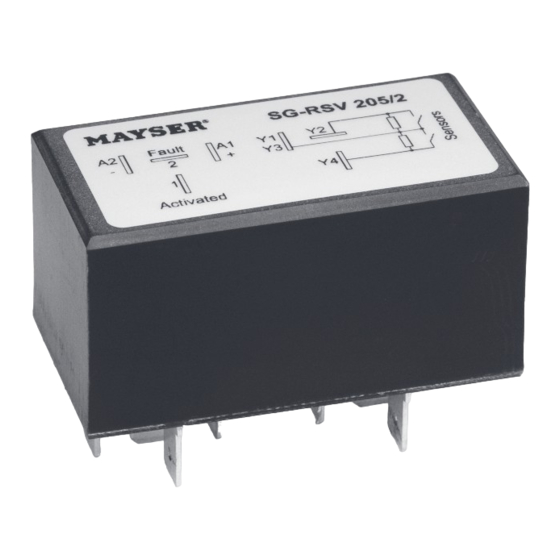
Control unit SG-RSV 205
1002378
SG-RSV 205/2
Semiconductor outputs
Original instructions
18–32 V=
Innovative by tradition.
Mayser GmbH & Co. KG
Örlinger Strasse 1–3
89073 Ulm
GERMANY
Tel.: +49 731 2061-0
Fax: +49 731 2061-222
E-mail: info.ulm@mayser.com
Website: www.mayser.com
Version 2
Advertisement
Table of Contents

Related Manuals for MAYSER SG-RSV 205


Summary of Contents for MAYSER SG-RSV 205
- Page 1 Innovative by tradition. Operating instructions Control unit SG-RSV 205 Version 2 1002378 SG-RSV 205/2 18–32 V= Mayser GmbH & Co. KG Semiconductor outputs Örlinger Strasse 1–3 89073 Ulm GERMANY Tel.: +49 731 2061-0 Fax: +49 731 2061-222 E-mail: info.ulm@mayser.com Original instructions...
-
Page 2: Table Of Contents
Offenders will be held liable for the payment of damages. All rights reserved in the event of the grant of a patent, utility model or design. © Mayser Ulm 2013 Page 2/12 Operating instructions SG-RSV 205 280513 v2.2cd... -
Page 3: About These Operating Instructions
About these operating instructions These operating instructions are part of the product. Mayser Polymer Electric accepts no responsibility or warranty claims for damage and consequential damage due to failure to observe the operating instructions. Ä Read the operating instructions carefully before use. -
Page 4: Intended Use
When installing the product in a switch cabinet, ensure sufficient clearance from heat sources (at least 2 cm). Observe correct terminal assignment Ä Observe the correct terminal assignment when connecting the supply voltage. Page 4/12 Operating instructions SG-RSV 205 280513 v2.2cd... -
Page 5: Parts Supplied
Several control units are stacked together in one large cardboard box. The documents are enclosed separately. Storage Ä Store control units in a dry place inside the original packaging. Ä Observe the storage temperatures given in the technical data. 280513 v2.2cd Operating instructions SG-RSV 205 Page5/12... -
Page 6: Product Overview
In the event of a cable break or supply voltage failure, both the “Activated” and the “Fault” outputs switch to LOW. The outputs take the form of short-circuit-proof semiconductor outputs. Flowchart Operating state: Normal Fault Normal Sensor X activated “Activated” output HIGH “Fault” output Page 6/12 Operating instructions SG-RSV 205 280513 v2.2cd... -
Page 7: Installation
(e.g. a switch cabinet). 1. Wire the sensors, outputs and supply voltage on the socket plate. Sensor 1 Sensor 2 2. Insert the 7 flat connectors into the relevant sockets. Plug in the control unit evenly. 280513 v2.2cd Operating instructions SG-RSV 205 Page7/12... -
Page 8: Commissioning
“Fault” output is set to HIGH (2) 3. Repeat step 1. 4. Disconnect sensor X. “Activated” output is set to LOW (1) “Fault” output is set to LOW (2) 5. Repeat step 1. Page 8/12 Operating instructions SG-RSV 205 280513 v2.2cd... -
Page 9: Recommissioning
The control unit works without a reset. If the sensor is released after activation, the “Activated” output returns to “LOW” after a delay t Ä After recommissioning, check the unit for proper functioning (see section Com- missioning). Connection example 280513 v2.2cd Operating instructions SG-RSV 205 Page9/12... -
Page 10: Maintenance And Cleaning
1. Check activated sensor; resistance < 400 ohms 2. Measured resistance deviates signifi- cantly Ä Replace sensor If supply voltage is correctly connected and Ä Replace control unit sensor is OK: control unit is faulty Page 10/12 Operating instructions SG-RSV 205 280513 v2.2cd... -
Page 11: Replacement Parts
Ä Contact Mayser-Support: Tel. +49 731 2061-0. Replacement parts Overall safety at risk CAUTION If the sensor and control unit are not replaced using original parts from Mayser, op- eration of the protection device may be impaired. Ä Only use original parts from Mayser. Disposal The control units produced by Mayser are professional electronic tools exclusively in- tended for commercial use (known as B2B devices). -
Page 12: Technical Data
85%, non-condensing Operating temperature −40 to +80 °C Storage temperature −40 to +80 °C Vibration fatigue limit 1 g in all 3 levels Dimensions (W × H × D) 58 × 41 × 30 mm Weight 70 g Page 12/12 Operating instructions SG-RSV 205 280513 v2.2cd...
Need help?
Do you have a question about the SG-RSV 205 and is the answer not in the manual?
Questions and answers