Table of Contents
Advertisement
Quick Links
Control unit SG-RS 309-2
EN | Operating instructions
1006747
Original instructions
SG-RS 309-2
DC 24 to 36 V / 8k2, 10k
Innovative by tradition.
Version 1
Mayser GmbH & Co. KG
Örlinger Straße 1–3
89073 Ulm
GERMANY
Phone: +49 731 2061-0
Fax: +49 731 2061-222
E-mail: info.ulm@mayser.com
Internet: www.mayser.com
Advertisement
Table of Contents

Related Manuals for MAYSER SG-RS 309-2


Summary of Contents for MAYSER SG-RS 309-2
- Page 1 Innovative by tradition. Control unit SG-RS 309-2 EN | Operating instructions Version 1 1006747 SG-RS 309-2 DC 24 to 36 V / 8k2, 10k Mayser GmbH & Co. KG Örlinger Straße 1–3 89073 Ulm GERMANY Phone: +49 731 2061-0 Fax: +49 731 2061-222 E-mail: info.ulm@mayser.com...
- Page 2 Offenders will be held liable for the payment of damages. All rights re- served in the event of the grant of a patent, utility model or design. © Mayser Ulm 2021 Page 2/23 Operating instructions SG-RS 309-2 110321 v1.01-RiO...
-
Page 3: Table Of Contents
Pressure-sensitive protection device actuated ......................17 Correlations ..................................18 Decommissioning ................................18 Recommissioning ................................18 Maintenance and cleaning ..............................19 Maintenance ..................................19 Cleaning ....................................19 Troubleshooting and remedies ............................19 Replacement parts ................................21 Disposal ....................................21 Technical data ..................................22 110321v1.01-RiO Operating instructions SG-RS 309-2 Page 3/23... -
Page 4: About This Manual
About this manual About this manual This manual is an integral part of the product. Mayser will assume no liability and provide no guarantee whatsoever for damages and consequential damages resulting from failure to comply with the manual. Validity This manual is valid only for the product specified on the title page. -
Page 5: Safety
To prevent irreparable damage to the product, the following safety instructions ap- ply. Ä Do not open the control unit Never open, tamper with or alter the control unit. 110321v1.01-RiO Operating instructions SG-RS 309-2 Page 5/23... -
Page 6: Residual Dangers
Protect the control unit against excessive EMC radiation. A strong electromagnet- ic signal can cause the control unit to switch to a safe OFF state. Residual dangers There are no known residual dangers associated with this product. Page 6/23 Operating instructions SG-RS 309-2 110321 v1.01-RiO... -
Page 7: Parts Supplied
Semiconductor output OSSD 1.2 Signal output Monitoring circuit 2 (Sensor 2) Semiconductor output OSSD 2.1 Semiconductor output OSSD 2.2 Signal output 11, 14; 31, 34 without function 21, 24; 41, 44 without function 110321v1.01-RiO Operating instructions SG-RS 309-2 Page 7/23... -
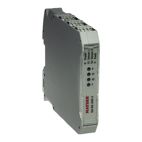
Page 8: Led Indicators
If there is a cable break between sensor 2 and the control unit, all OSSDs from mon- itoring circuit 1 and 2 are in OFF state, signal outputs M1 and M2 are HIGH. The yel- low LED “S1” and the red LED “F” are flashing. Page 8/23 Operating instructions SG-RS 309-2 110321 v1.01-RiO... -
Page 9: Reset
Conditions for the signal pulse of the higher-ranking control system: Signal duration min. / max. 60 ms / 13 s Signal voltage min. / max. 10 V / 24 V Fault Reset Reset signal control 110321v1.01-RiO Operating instructions SG-RS 309-2 Page 9/23... -
Page 10: Manual Reset
If the actuation period is not reached, then reset will not take place. If the actuation period max. is exceeded, the control unit changes to the mode: “Fault / System error” (see Chapter Troubleshooting and remedies). Page 10/23 Operating instructions SG-RS 309-2 110321 v1.01-RiO... -
Page 11: Installation
If the control unit is overheated due the effects of external heat, this can result in functional impairment or failure of the pressure-sensitive protection device. Always ensure sufficient distance from heat sources (at least 2 cm). Ä 110321v1.01-RiO Operating instructions SG-RS 309-2 Page 11/23... -
Page 12: Reset
The reset (with reset function) can be set up using a higher-level control (or a push- button): Controlled reset Wire the control output to cable terminal S14. Ä Terminals S13 and S15 remain unconfigured. Control system Page 12/23 Operating instructions SG-RS 309-2 110321 v1.01-RiO... -
Page 13: Manual Reset
In an electromagnetic extreme case (surge pulse) the signal outputs may flicker. This does not affect the safety function. Protect the control unit from excessive EMC radiation. Ä Connection examples Connection examples 1 Monitoring Monitoring circuit 1 circuit 2 110321v1.01-RiO Operating instructions SG-RS 309-2 Page 13/23... - Page 14 Installation Connection examples 2 Monitoring Monitoring circuit 1 circuit 2 Manual reset Monitoring Monitoring circuit 1 circuit 2 Reset Contact duplication Monitoring Monitoring circuit 1 circuit 2 • • • Reset Page 14/23 Operating instructions SG-RS 309-2 110321 v1.01-RiO...
-
Page 15: Commissioning
OSSDs from monitoring circuit 1 and 2 in OFF state signal outputs M1 and M2 at HIGH 7. Repeat step 1. 8. Disconnect the power supply for at least 500 ms. the control unit will restart 110321v1.01-RiO Operating instructions SG-RS 309-2 Page 15/23... -
Page 16: Controlled Reset And Manual Reset
7. Disconnect sensor 1. yellow LED “S1“ and red LED ”F“ are flashing OSSDs from monitoring circuit 1 and 2 in OFF state signal outputs M1 and M2 at HIGH 8. Repeat step 1. Page 16/23 Operating instructions SG-RS 309-2 110321 v1.01-RiO... -
Page 17: Pressure-Sensitive Protection Device Actuated
If actuation of the pressure-sensitive protection device ends, different states are pos- sible on the output signal switching devices of the control unit. This depends on the selected reset type (see chapter Operation, subchapter Reset). 110321v1.01-RiO Operating instructions SG-RS 309-2 Page 17/23... -
Page 18: Correlations
Ä switched back on unintentionally. Affix a clear warning on the pressure-sensitive protection device warning that Ä states it is temporarily or definitively decommissioned. Recommissioning Carry out commissioning (see chapter Commissioning). Ä Page 18/23 Operating instructions SG-RS 309-2 110321 v1.01-RiO... -
Page 19: Maintenance And Cleaning
2. Actual value ≠ set value: Sensor faulty 3. Replace sensor Control unit is faulty 1. Connect 8k2 or 10k resistor to termi- nals Y3, Y4 2. Fault not remedied: Replace control unit 110321v1.01-RiO Operating instructions SG-RS 309-2 Page 19/23... - Page 20 S13 and Control unit is faulty Replace control unit Ä The fault can still not be removed? Contact Mayser support: Phone +49 731 2061-0. Ä In case of queries, have the information on the type plate at hand. Ä Type plate A type plate for identification of the control unit is affixed on the side.
-
Page 21: Replacement Parts
Replacement parts Replacement parts CAUTION Overall safety endangered If the sensor is not replaced with original Mayser parts, operation of the protec- tive device may be impaired. Only use original parts from Mayser. Ä Disposal Control unit The devices produced by Mayser are professional electronic tools exclusively intend- ed for commercial use (so-called B2B devices). -
Page 22: Technical Data
- 0.7 V Switching voltage (min.) Switching current (max.) 100 mA Switching current (min.) > 0 mA Nominal output (max.) 3.6 W Switching operations, mechanical – Line length (max.) 10 m Page 22/23 Operating instructions SG-RS 309-2 110321 v1.01-RiO... - Page 23 Category 1 Class B Vibration fatigue limit Frequency range 10 to 55 Hz Amplitude 0.15 mm Cycles per axis Protective coating Dimensions (W × H × D) 17.5 × 99 × 114.5 mm Weight 115 g 110321v1.01-RiO Operating instructions SG-RS 309-2 Page 23/23...
Need help?
Do you have a question about the SG-RS 309-2 and is the answer not in the manual?
Questions and answers