
Subscribe to Our Youtube Channel
Related Manuals for ABB HVC 100C


Summary of Contents for ABB HVC 100C
- Page 1 — USER MANUAL HVC 100C / HVC 150C with Depot Charge box User and Operation Manual Version 0.6...
- Page 2 This document contains information about one or more ABB products and may include a descrip- tion of or a reference to one or more standards that may be generally relevant to the ABB products. The presence of any such description of a standard or reference to a standard is not a representa- tion that all of the ABB products referenced in this document support all of the features of the de- scribed or referenced standard.
- Page 3 Version control Ver- Date Remarks sion V0.1-0.3 01-12-2018 Released next version with pilot feedback V0.4 01-02-2019 Released next version with updated info sequential charging V0.5 01-05-2019 Updated sequential charging information V0.6 22-05-2019 Updated document nr and format Document: v0.6 / Document No.: 6AGA000008-0102-EN | Date: 22-05-2019 Page 3 of 23...
-
Page 4: Table Of Contents
Contents Glossary ................................5 1 Introduction ..............................6 Preface ................................6 Intended use of this document........................6 Intended use of the charger .......................... 6 Owner responsibilities ............................ 7 Signs..................................7 Safety regulations ............................9 2 Description of the product ......................... 10 Overview of the system .......................... -
Page 5: Glossary
Glossary Combined Charging System. A universal AC and DC charging system, also referred to as ‘Combo’. Direct Current. Electric Vehicle. Owner The legal owner of the charger. OCPP Open Charge Point Protocol. Open standard for communication with charge stations. Protective Earth. RCBO Residual-current Circuit Breaker with Overload protection. -
Page 6: Introduction
Introduction Preface The HVC-C product line is the new ABB solution for Overnight Charging of Heavy Vehi- cles. The product line allows 100kW and 150kW charging with up to 3 charging outlets per one charger. The charging of the vehicles is done sequentially following the first come, first serve principle. -
Page 7: Owner Responsibilities
ABB’s warranty. Neither ABB nor its affiliates shall be liable to the purchaser of this product or third par- ties for damages, losses, costs or expenses incurred by purchaser or third parties as a... - Page 8 WARNING Pinch Hazard Identifies a hazard that could result in injuries, in which some body parts are pinched or crushed. CAUTION Various Identifies a hazard that could result in damage to the ma- chine, other equipment, and/or environmental pollution NOTICE Contains remarks, suggestions or advice.
-
Page 9: Safety Regulations
Safety regulations WARNING If a charge outlet is damaged, take the following steps: Do not use the damaged charge outlet. 2. Contact the owner / site operator. WARNING If there is an emergency Push the emergency stop. 2. Contact the owner / site operator. 3. -
Page 10: Description Of The Product
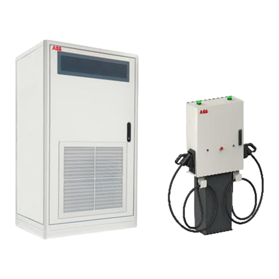
Description of the product Overview of the system A. Charge cabinet 100-150kW B. Depot charge boxes (up to 3 per charger with sequential charging) Charge cabinet Door Door handle / lock 3G Antenna Air inlets (also on the left and back side) Air outlet CAUTION The Power Cabinet has air inlets (D) and an air outlet (E) to control... -
Page 11: Depot Charge Box
Depot charge box The user operated components are indicated on below: A. LED beacon B. Emergency button C. Stop button D. Door handle & lock E. Connector holder F. CCS charge cable G. External connections Overview LED colors and state: Document: v0.6 / Document No.: 6AGA000008-0102-EN | Date: 22-05-2019 Page 11 of 23... -
Page 12: Charger Configurations
Charger configurations The charger is built up with a modular architecture. Supported charging standards are: Product Description HVC-100C CE 100kW charge cabinet configuration with 1-3 Depot charge boxes, supporting CCS-2 with CE certification HVC-150C CE 150kW charge cabinet configuration with 1-3 Depot charge boxes, supporting CCS-2 with CE certification HVC-100C UL 100kW charge cabinet configuration with 1-3 Depot charge boxes,... -
Page 13: Charging Instruction
Charging instruction Charging with 1 Depot Charge Box Start charging: Park the electric vehicle with the charge inlet within reach of the connector. 2. Turn off the electric vehicle. 3. Connect the charger’s connector to the vehicle’s charge inlet. 4. The charger will automatically start to charge the vehicle after the preparation phase, and will indicate the progress by the LED state (see 2.3). -
Page 14: Emergency Stop
Stop charging: 7. If there is another bus connected to the charger that requires bulk charging the charger will stop the preconditioning and automatically switch to the bus that requires bulk charging. 8. The preconditioning will continue in a 20 min loop between all the connected bus until the charge session is stopped. -
Page 15: Operator Instructions
The following points must be checked regularly: • Internal RCDs and RCBOs need to be tested on correct functioning on a regular basis. During the yearly maintenance round that is advised to be executed by a certified ABB technician, this will be checked. •... -
Page 16: Emergency Stop Inspection
The site operator or helpdesk is the first response to a customer call. The helpdesk can remo- tely solve simple problems for the customer. In special cases the site operator with knowledge of the charger can be asked by ABB support to report about the status of some internal components of the charger. Therefore a brief description of the position and function of these components is described on the next pages. -
Page 17: Overview Of The Depot Charge Box
4.3.2 Overview of the Depot charge box Front door Depot charge box Door handle / lock (per depot box Unique system key) WARNING Do not open the Depot charge box door if you are not familiar with working with high voltage and high current. Document: v0.6 / Document No.: 6AGA000008-0102-EN | Date: 22-05-2019 Page 17 of 23... -
Page 18: Component Overview Power Cabinet
4.3.3 Component overview Power Cabinet The main components as can be seen with an open front door: Main switch MCB (Q17) AC power supply for ACM RCD (Q13) control RCD (Q12) redundant control Display 4.3.4 Component overview Depot Charge Box The main components as can be seen with an open front door: SPD (F2) AC Power Supply MCB (F1) AC Power Supply... -
Page 19: Technical Functioning
Technical functioning 4.4.1 Normal operation Normal positions of the different switches and breakers when the charger is in operation (idle; not charging): Power Cabinet • Main switch (A): Vertical (“1”) • MCB (Q17) AC power supply for ACM (B): up •... - Page 20 NOTICE Every box has its own power supply line. Following procedure should be performed for every box which should be powered off. Document: v0.6 / Document No.: 6AGA000008-0102-EN | Date: 22-05-2019 Page 20 of 23...
-
Page 21: Contact Information
Contact information NOTICE In case of problems Contact the site operator. ABB Service department - PLEASE INSERT YOU CONTACT DETAILS- Document: v0.6 / Document No.: 6AGA000008-0102-EN | Date: 22-05-2019 Page 21 of 23... - Page 22 Appendix: A. WEEE disposal – 2012-19/EU Document: v0.6 / Document No.: 6AGA000008-0102-EN | Date: 22-05-2019 Page 22 of 23...
- Page 23 NOTES Document: v0.6 / Document No.: 6AGA000008-0102-EN | Date: 22-05-2019 Page 23 of 23...
Need help?
Do you have a question about the HVC 100C and is the answer not in the manual?
Questions and answers