
Related Manuals for ABB HVC-PD


Summary of Contents for ABB HVC-PD
- Page 1 — IN STA L L AT I ON G U ID E HVC-PD E-Bus Charger Installation Guide for EU products Version 3.1...
- Page 2 ABB cannot be held liable for errors in the translation. This document and parts thereof must not be reproduced or copied without written permission from ABB, and the contents there of must not be imparted to a third party nor used for any unauthorized purpose.
- Page 3 First release of HVC E-Bus Charger systems based on 450 kW architecture platform. 22-05-2019 Change the name to HVC-PD E-Bus Charger and describe only a standard installation with pole. Improve description about placement of pole in relation with bus. Change description of DC connection in Power Cabinet (according to Mantis CR-11229).
-
Page 4: Table Of Contents
1.5. Environment and disposal of waste 1.6. Contact information Description of the product 2.1. Overview of the system 2.1.1. Standard HVC-PD 150 kW E-Bus Charger system 2.1.2. Standard HVC-PD 300 kW E-Bus Charger system 2.1.3. Standard HVC-PD 450 kW E-Bus Charger system 2.1.4. - Page 5 HVC-PD E-Bus Charger Installation Guide 4.2. Construct foundation of the Power Cabinet 4.2.1. Options 4.2.2. Workflow with concrete foundation 4.2.3. Workflow with metal frame foundation 4.2.4. Workflow mounting Power Cabinet direct on a floor (footprint) 4.3. Construct foundation of the Charge Pole 4.3.1.
- Page 6 HVC-PD E-Bus Charger Installation Guide 5.9.1. Route the cable to the terminal blocks 5.9.2. Connect the communication fiber cables 5.10. Close the door of the Power Cabinet 5.11. Unpack the Charge Pole components 5.11.1. Before unpacking 5.11.2. Remove packaging 5.12. Move the Charge Pole to position 5.13.
- Page 7 HVC-PD E-Bus Charger Installation Guide Signal connection diagram Ground overview of the system WEEE disposal – 2012-19/EU Document: v3.1 / Document No.: 6AGA000008-0600-EN | Date: 22-05-2019 Page 7 of 139...
- Page 8 HVC-PD E-Bus Charger Installation Guide Glossary OPP Charge Alternating Current. Is a trade name of fast charging method for electric vehicles. ACS Control Module Owner The legal owner of the charger. Automatic Control System. In this charger Pantograph system the pantograph.
-
Page 9: Introduction
This guide describes the planning and physical installation of the HVC-PD E-Bus Charger at its location. The HVC-PD E-Bus Charger is a DC fast charger system for hybrid or electrical buses that are compatible with the OPP Charging standard . It is not permitted to use the HVC-PD E-Bus Charger to charge any other equipment, or to use the HVC-PD E-Bus Charger for any other purposes. -
Page 10: Safety Regulations
HVC-PD E-Bus Charger Installation Guide WARNING Pinch Hazard Identifies a hazard that could result in injuries in which some body parts are pinched or crushed. WARNING Fall Hazard Identifies a hazard that could result in injury due unsafe work at height. -
Page 11: Tilting And Handling
ABB’s warranty policy. • Neither ABB nor its affiliates shall be liable to the purchaser of this product or third parties for damages, losses, costs or expenses incurred by purchaser or third parties... -
Page 12: Electric Hazards
Instruct and warn people about the potential harmful high voltages. 5. The installation and maintenance personnel must supply their own lighting equipment, since the HVC-PD E-Bus Charger has no lights inside the cabinet. 6. Always connect the Protective Earth (PE) first, before connecting the neutral (N) and Phase (P) wiring. -
Page 13: Environment And Disposal Of Waste
1.5. Environment and disposal of waste CAUTION Always observe the local rules and regulations with respect to processing (non-reusable) parts of the HVC-PD E-Bus Charger. Document: v3.1 / Document No.: 6AGA000008-0600-EN | Date: 22-05-2019 Page 13 of 139... -
Page 14: Contact Information
HVC-PD E-Bus Charger Installation Guide 1.6. Contact information ABB in your country Please contact ABB in your country for sales, delivery and service information. ABB EV Infrastructure global ABB EV Infrastructure Address Delftweg 65 2289 BA Rijswijk The Netherlands Telephone... -
Page 15: Description Of The Product
ABB offers a standard delivery system configurations with a DC charge power of 150, 300 or 450 kW. Additional needed components can be ordered separately and are not part of the standard delivery. -
Page 16: Standard Hvc-Pd 300 Kw E-Bus Charger System
HVC-PD E-Bus Charger Installation Guide 2.1.2. Standard HVC-PD 300 kW E-Bus Charger system The following parts are provided for this system configuration: • HVC 300P Power Cabinets (ABB6AGC069043): ▪ 1x HVC 150 Power Cabinet ▪ 1x HVC 150S Power Cabinet •... -
Page 17: Power Cabinet
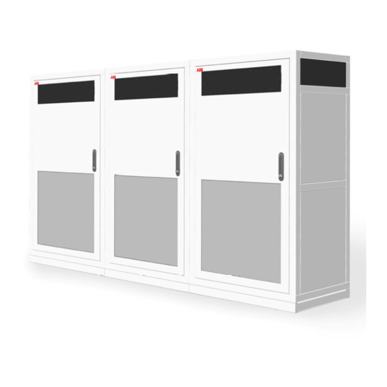
HVC-PD E-Bus Charger Installation Guide 2.1.4. Power Cabinet Outside view of the Power Cabinet Base cover 3G Antenna Air outlet Air inlets (also on the left and back side) Door Door handle / lock Inside view of the Power Cabinet... -
Page 18: Acs Control Module
HVC-PD E-Bus Charger Installation Guide 2.1.5. ACS Control Module Outside view of the ACS Control Module Door Locks WiFi coax connector In- and outputs for cables from Power Cabinet and to pantograph In- and outputs DC power cables Inside view of the ACS Control Module... -
Page 19: Junction Box
HVC-PD E-Bus Charger Installation Guide 2.1.6. Junction Box Outside view Junction Box Cover In- and outputs DC power cables Output DC- OVP sensing cable 2.1.7. Charge Pole Outside view Charge Pole Door Emergency button (EMO) Charge state indicator light (beacon) -
Page 20: Accessories
Tension spring Collector head 2.2. Accessories The following parts can be ordered at the time of the initial order or afterwards. Contact ABB Sales department (see Contact information on Page 14 for contact details). 2.2.1. Foundation for Power Cabinet Concrete foundation The concrete foundation can be used to install the Power Cabinet on soil. -
Page 21: Foundation For Charge Pole Construction
HVC-PD E-Bus Charger Installation Guide Metal frame foundation The metal frame foundation can be used to install the Power Cabinet on a solid surface. Foundation Front border cover Rear border cover Amount Part number Description 4EPY420133R1 HxC power cabinet metal foundation 2.2.2. -
Page 22: Communication Glass Fiber Cable
HVC-PD E-Bus Charger Installation Guide Pulse tube foundation The pulse tube foundation can be used to install the Charge Pole construction on soil. For this option, contact ABB Sales department (see Contact information on Page 14 for contact details). 2.2.3. Communication glass fiber cable The CAN and Ethernet communication between the Power Cabinet and Charge control set is done via a glass fiber cable. -
Page 23: Rfid Unit
HVC-PD E-Bus Charger Installation Guide 2.2.4. RFID unit Needed when multiple Charge Poles are installed close to each other (distance between each other is lower than 12 m). Amount Part number Description RFU 630-131xx RFID RFU63x (Sick) SSL-2J04-G10ME (part RFID Ethernet cable 10 m (male connector, M12, 4-pin, straight,... -
Page 24: Project Planning
The different phases of the full project plan are shown in the figure below: A. Preparation The owner / site operator has ordered a HVC-PD E-Bus Charger. In this phase all preparation work must be done before the contractor can do the civil and electrical works. -
Page 25: Preparation
The contractor is responsible for all construction documentation of the site, among other things: drawings, calculations, certifications, licenses and test reports. The location of the HVC-PD E-Bus Charger must be chosen. See section Location on Page 27 and section Geometry of infrastructure on Page 28. -
Page 26: Permits
This section lists a number of points of attention. 3.2.1. Power connection The HVC-PD E-Bus Charger requires high current (400 V AC 265 A for 150 kW or 530 A for 300 kW or 713 A for 450 kW) connections. A normal domestic or small business power connection is not sufficient. -
Page 27: Upgrade Grid
HVC-PD E-Bus Charger Installation Guide 3.3. Upgrade grid The HVC-PD E-Bus Charger can be connected directly to the electrical grid or to an existing customer low voltage power distribution cabinet. In both cases a 265 A, 400 V AC, 50 Hz,... -
Page 28: Geometry Of Infrastructure
HVC-PD E-Bus Charger Installation Guide 3.5. Geometry of infrastructure 3.5.1. Required space for the Power Cabinet A single HVC 150 (or HVC 150S) Power Cabinet requires a minimum space of 1170 x 2070 mm (W x D) or 1370 x 1970 mm (W x D). This space is calculated as follows: •... -
Page 29: Placement Of Multiple Cabinets
• Maximum allowed pressure drop = 300 pA. If the pressure drop of the room is higher than 300 pA an extra fan should be placed. Contact ABB Sales department (see Contact information on Page 14 for contact details). 3.5.2. Placement of multiple cabinets There are some possible configurations for the placement of multiple HVC 150 systems, see picture below. -
Page 30: Required Space For The Charge Pole
HVC-PD E-Bus Charger Installation Guide When placing multiple HVC 150 systems, it is necessary to take the following into account: • Cabinets can be placed side-by-side; • Cabinets can be placed back-to-back with 200 mm distance (2x 100 mm) or when the sides are free with 0 mm distance;... -
Page 31: Pole Position In Relation To The Bus
NOTICE Before ordering the Charge Pole the correct position of the pantograph within the pole must be calculated by ABB. This is determined during the site survey for placement of the pole and is performed by ABB. Contact ABB Sales department (see Contact information on Page 14 for contact details). -
Page 32: Pole Position In Sideways Direction Of The Bus
HVC-PD E-Bus Charger Installation Guide 3.6.2. Pole position in sideways direction of the bus The minimum distance is and the maximum between the front of the pole and side of the bus is 900 mm to 1800 mm respectively. The picture below shows how to calculate the correct position of the pantograph (measured middle of the collector head) within the Charge Pole with respect to the position of the bus. - Page 33 The pole can be placed on the left side or on the right side (driver side) of the bus. This must be communicated with ABB before ordering the Charge Pole. This will also be noted by ABB during the site survey for the placement of the pole. Contact ABB Sales department (see Contact information on Page 14 for contact details).
-
Page 34: Maximum Slope Of The Road In Sideways Direction
The road inclination should be known before the pole can be built. This must be communicated with ABB before ordering the Charge Pole. This will also be noted by ABB during the site survey for the placement of the pole. Contact ABB Sales department (see Contact information on Page 14 for contact details). -
Page 35: Electrical Engineering
HVC-PD E-Bus Charger Installation Guide The installation can handle a road inclination smaller than 2.5° without any modification to the position of the pantograph. When the road inclination is between 2.5° and 5.0°, the position of the pantograph must be adjusted during production of the pole. The road inclination should not be greater than 5.0°. -
Page 36: Lightning Protection
HVC-PD E-Bus Charger Installation Guide Example of civil installation for a HVC 450 kW system Foundations of Power Cabinet Foundation of Charge Pole Flexible conduit for DC power cables Flexible conduit for AC utility power, PE wire and data cables... -
Page 37: Construction
4. Construction 4.1. About construction The construction phase includes all work required to prepare the location and make it ready for the placement and connection of the HVC-PD E-Bus Charger. The construction phase can start when: • All engineering work is done. -
Page 38: Construct Foundation Of The Power Cabinet
HVC-PD E-Bus Charger Installation Guide Transport Arrangement for the delivery of the HVC-PD E-Bus Charger with the ABB Delivery department. See Contact information on Page 14 for contact details. The delivery time is at least four months. 4.2. Construct foundation of the Power Cabinet 4.2.1. -
Page 39: Workflow With Concrete Foundation
HVC-PD E-Bus Charger Installation Guide 4.2.2. Workflow with concrete foundation WARNING Make sure that personnel cannot be crushed or become trapped while moving the foundation. Be aware that the weight of the concrete foundation is about 1300 kg. CAUTION Before you lower the foundation, remove sharp edges of the cable holes (B) in the foundation to protect the cables. - Page 40 HVC-PD E-Bus Charger Installation Guide NOTICE This extra cable length is required to connect the AC power cable with the connectors in the Power Cabinet without problems. 11. Place both cover plates on the appropriate place on the foundation. 12. Secure the top cover plate with M16 bolts (4x) and the front cover plate with M12 bolts (4x).
-
Page 41: Workflow With Metal Frame Foundation
HVC-PD E-Bus Charger Installation Guide 4.2.3. Workflow with metal frame foundation Place the frame (A) in the desired position and mark the position of the holes for drilling. NOTICE The hole distance of 655mm on either side of the metal frame foundation is not equal to the hole distance (680 mm) from the HVC 150(S) cabinet. -
Page 42: Workflow Mounting Power Cabinet Direct On A Floor (Footprint)
HVC-PD E-Bus Charger Installation Guide 4.2.4. Workflow mounting Power Cabinet direct on a floor (footprint) Drill and tap holes in the floor at the indicated positions (A). The holes must be suitable for bolt size M16. Make rectangular holes on the indicated positions (B) and (C). For detail drawings bottom view of Power Cabinet see Appendix A Dimensions Power Cabinet. -
Page 43: Construct Foundation Of The Charge Pole
Use a tube foundation to get a firm fixation on soil. This tube foundation can be used if there are space restrictions, for example close to a building. Contact the ABB Sales department for more information and possibilities, see Contact information on Page 14 for contact details. - Page 44 100 kPa, no soil compact actions has to be taken. If the concrete foundation will be installed on another ground type than sand (like rock, gravel, clay or peat), take contact with the ABB Sales department, see Contact information on Page 14 for contact details.
- Page 45 (see Contact information on Page 14 for contact details). Installing the concrete base plate Preconditions: 4x WLL 3/5.0 tons lifting claws (are not delivered by ABB, use for example Starcon Universal Lifting Claws, art.no. 99.11590082B). WARNING Make sure that personnel cannot be crushed or become trapped while moving the foundation.
- Page 46 Installing the counter weights Preconditions: 2x WLL 1.5/2.5 tons lifting claws (are not delivered by ABB, use for example Starcon Universal Lifting Claws, art.no. 99.11590081B). With the concrete base plate in position the counter weights can be installed. These counter weights are needed to keep the charging pole construction up right during extreme weather conditions and to prevent the construction from tilting.
- Page 47 HVC-PD E-Bus Charger Installation Guide Compaction the soil around the concrete foundation Before filling the gap around the concrete foundation ensure that all: • Conduits are installed to the concrete base plate. • The conduits must come out of the holes on the top side of the concrete base plate with a length of about 250 mm.
-
Page 48: Cabling
CAUTION ABB is not responsible for damage caused to the Charger system due to the use of mechanical lugs, and is not covered by the warranty. Document: v3.1 / Document No.: 6AGA000008-0600-EN | Date: 22-05-2019... -
Page 49: Charge System Configurations
HVC-PD E-Bus Charger Installation Guide 4.4.2. Charge system configurations Overview electrical connections of a HVC-PD 150 kW charge system Overview electrical connections of a HVC-PD 300 kW charge system Document: v3.1 / Document No.: 6AGA000008-0600-EN | Date: 22-05-2019 Page 49 of 139... -
Page 50: Ac Power Cable
4x communication cables; 8x glass fiber (4 fibers are required, 4 are for spare). ➢ The 8x glass fiber cable is a special cable that will be supplied by ABB. Use local regulations and datasheet of the manufacturer to determine the cable cross section for the DC power cables. -
Page 51: Cables Between The Power Cabinets
HVC-PD E-Bus Charger Installation Guide 4.4.5. Cables between the Power Cabinets The following cables are not in the scope of supply of ABB. • 1x PE cable; • 1x Interlock cable; • 1x CAN cable. NOTICE For detailed information about type of glass fiber cable which are needed, see Communication glass fiber cable on Page 22. -
Page 52: Internet Connection
In most cases the integrated 3G modem is used for wireless internet access. A customer SIM card is not required. If there is no 3G signal available, a standard wired internet connection is required. For this option, contact ABB Sales department (see Contact information on Page 14 for contact details). -
Page 53: Placement And Connection
HVC-PD E-Bus Charger Installation Guide 5. Placement and Connection 5.1. About placement and connection When the construction phase is finished, the HVC-PD E-Bus Charger can be placed and connected. The planning steps for the placement and connection phase are shown in the figure below. -
Page 54: Route The Cables
HVC-PD E-Bus Charger Installation Guide Connect the PE wire to the Charge Pole on Page 93 and Connect cables ACS Control Module on Page 97. Install masks plate work on Page 109 and Grouting of the pole construction on Page 115. -
Page 55: Unpack Power Cabinet
HVC-PD E-Bus Charger Installation Guide For the DC power cables, make sure that a cable length of 1000 mm is available above the surface for internal routing in the cabinet. For the other cables, make sure that a cable length of 3000 mm is available above the surface for internal routing in the cabinet. -
Page 56: Remove Packaging
HVC-PD E-Bus Charger Installation Guide 5.3.2. Remove packaging Preconditions • Tools: spanner (size 24). Remove the packaging material from the Power Cabinet. Remove the bag which contain the keys, cover caps and mounting material that are attached with tape on one of the lifting eyebolt at the top of the cabinet. -
Page 57: Move Cabinet With A Hoist
HVC-PD E-Bus Charger Installation Guide DANGER Make sure that the main switch of the power supply group for the product is set to the OFF position. Do a voltage check to make sure that the electrical power is disconnected from the system. Secure against resetting. -
Page 58: Move Cabinet With A Forklift Truck
HVC-PD E-Bus Charger Installation Guide Insert the bolts (A) or (B) into the holes at the opposite corners of the cabinet, if not placed upon delivery. Tighten the bolts. Connect the hoisting equipment (C). CAUTION Keep the hoisting angle below 60⁰. -
Page 59: Install Power Cabinet Onto The Foundation
HVC-PD E-Bus Charger Installation Guide 5.5. Install Power Cabinet onto the foundation 5.5.1. Connect Power Cabinet to foundation Preconditions: • Tools: spanner (size 24). • Cover caps (4x) that were removed from the Power Cabinet (bag with parts). • The Power Cabinet is about 500 mm above its location. - Page 60 HVC-PD E-Bus Charger Installation Guide Placement on metal frame foundation Foundation Power Cabinet Cables Tapped holes Carefully lower the Power Cabinet (B) onto the foundation (A). Make sure that you do not trap the cables (C). Make sure that the cabinet is aligned with the tapped holes (D).
-
Page 61: Open The Door Of The Power Cabinet
HVC-PD E-Bus Charger Installation Guide Tighten the bolts. Remove the swivel eye bolts or lifting loops (A). Place the cover caps (B) in the holes (4x). 5.5.2. Open the door of the Power Cabinet Preconditions: • Key that were removed from the Power Cabinet (bag with parts). -
Page 62: Move The Sliding Plate Of The Guidance Plates Of The Cabinet
HVC-PD E-Bus Charger Installation Guide 5.5.3. Move the sliding plate of the guidance plates of the cabinet Preconditions: • Tools: spanner (size 13). Loosen the bolts (A). Move the sliding plate (B) of the 2 guidance plates. 5.5.4. Route cables through guidance plates Route the cables (A) through the right guidance plates (B). -
Page 63: Move Sliding Plates Of The Guidance Plates Of The Cabinet
HVC-PD E-Bus Charger Installation Guide NOTICE A length of 3000 mm is required, because the connection of the cables with the connectors in the Power Cabinet is at the middle of the cabinet. 5.5.5. Move sliding plates of the guidance plates of the cabinet Preconditions: •... -
Page 64: Install Border Covers Of The Power Cabinet
HVC-PD E-Bus Charger Installation Guide 5.5.6. Install border covers of the Power Cabinet Preconditions: • Tools: spanner (size 8 and 10). • M6 nuts and washers (4x) that were removed from the Power Cabinet (bag with parts). • M5 bolts (4x) that were removed from the Power Cabinet (bag with parts). -
Page 65: Install Front Cover Plate On Foundation
HVC-PD E-Bus Charger Installation Guide Put the front border cover (A) against the bottom front of the Power Cabinet. Put the rear border cover (B) against the rear front of the Power Cabinet. Insert the M5 bolts (C) into the holes (8x). -
Page 66: Connect Ac Power Cable And Pe Wires Power Cabinets
HVC-PD E-Bus Charger Installation Guide Insert the M12 bolts (C) into the holes (4x). Tighten the bolts. 5.6. Connect AC power cable and PE wires Power Cabinets 5.6.1. Remove the protection covers Preconditions: • Tools: cross-head screwdriver Remove the protection plate (A) by loosening the screws (B). -
Page 67: Connect The Pe Wire Of The Ac Power Cable
HVC-PD E-Bus Charger Installation Guide 5.6.2. Connect the PE wire of the AC power cable Preconditions: • Tools: wire cutter, wire stripper pliers, wire-end ring, spanner (size 19), torque wrench (size 19). DANGER Make sure that the main switch of the power supply group for the product is set to the OFF position. -
Page 68: Connect The Ac Power Cable
HVC-PD E-Bus Charger Installation Guide 5.6.3. Connect the AC power cable Preconditions: • Tools: wire cutter, wire stripper pliers, spanner (size 19), torque wrench (size 19). DANGER Make sure that the main switch of the power supply group for the product is set to the OFF position. -
Page 69: Install The Protection Covers
HVC-PD E-Bus Charger Installation Guide 5.6.4. Install the protection covers Preconditions: • Tools: cross-head screwdriver Take the 3 protection covers that was removed in Remove the protection covers on Page Place the protection covers (D) back on the connector blocks (C). -
Page 70: Install Lightning Protection (Optional)
Leave the main switch switched off. The Power Cabinet is not ready for use yet. If there is no appointment for commissioning yet, contact the ABB Delivery department to make an appointment for commissioning. See Contact information on Page 14 for contact details. -
Page 71: Connect The Pe Wire To The Charge Pole
HVC-PD E-Bus Charger Installation Guide 5.6.6. Connect the PE wire to the Charge Pole NOTICE The PE wire to the Charge Pole is only connected within the HVC 150 Power Cabinet, see for more details section Cabling on Page 48. -
Page 72: Connect The Pe Wire Between The Power Cabinets
HVC-PD E-Bus Charger Installation Guide 5.6.7. Connect the PE wire between the Power Cabinets Preconditions: • Tools: wire cutter, wire stripper pliers, wire-end ring, spanner (size 19), torque wrench (size 19). Both PE wire connection must be made between the HVC 150 and the first HVC 150S and between both HVC 150S, see also section Cabling on Page 48: Cut the PE wire of the power cable to the correct length to reach the PE rail. -
Page 73: Remove The Protection Cover
HVC-PD E-Bus Charger Installation Guide 5.7.1. Remove the protection cover Remove the protection plate (A) by loosening the screws (B) (4x). Put the protection plate and screws in a safe location as it will be installed again later on. 5.7.2. Connect the DC power cables Cut the wires of the DC power cable to the correct lengths to reach the connectors. -
Page 74: Install The Protection Cover
HVC-PD E-Bus Charger Installation Guide 5.7.3. Install the protection cover Take the protection plate that was removed in Remove the protection cover on Page 73. Place the protection plate (A) back over the DC connector blocks and secure the plate by the screws (B) (4x). -
Page 75: Connect The Ac Utility Power Cable
HVC-PD E-Bus Charger Installation Guide Preferred cable route Route the AC utility cable to the terminal block (A). Refer to the figure for the preferred cable route inside the cabinet (only within the HVC 150). Route the Interlock cable(s) to the terminal block (B). Refer to the figure for the preferred cable route inside the cabinet. -
Page 76: Connect The Interlock Cable For The Hvc 150 Kw System
HVC-PD E-Bus Charger Installation Guide 5.8.3. Connect the Interlock cable for the HVC 150 kW system Interlock cable connection in the master HVC 150: Terminal block Interlock cable from/to ACS Control Module (ACM) Move the cable towards the terminal block (A). -
Page 77: Upgrade The Interlock Connection To The Hvc 300 Kw System
HVC-PD E-Bus Charger Installation Guide 5.8.4. Upgrade the Interlock connection to the HVC 300 kW system Interlock cable connection in the master HVC 150: Terminal block Interlock cable from/to ACS Control Module (ACM) Interlock cable from/to slave 1 HVC 150S Move the cables towards the terminal block (A). - Page 78 HVC-PD E-Bus Charger Installation Guide Interlock cable connection in slave 1 HVC 150S: Terminal block Interlock cable from/to master HVC 150 Move the cables towards the terminal block (A). Strip 11 mm of the insulation from the ends of only the White and Brown wire! Crimp a ferrule onto the end of the White and Brown wire.
-
Page 79: Upgrade The Interlock Connection To The Hvc 450 Kw System
HVC-PD E-Bus Charger Installation Guide 5.8.5. Upgrade the Interlock connection to the HVC 450 kW system Interlock cable connection in slave 1 HVC 150S: Terminal block Interlock cable from/to master HVC 150 Interlock cable from/to slave 2 HVC 150S Move the cables towards the terminal block (A). - Page 80 HVC-PD E-Bus Charger Installation Guide Interlock cable connection in slave 2 HVC 150S: Terminal block Interlock cable from/to slave 1 HVC 150S Move the cables towards the terminal block (A). Strip 11 mm of the insulation from the ends of only the White and Brown wire! Crimp a ferrule onto the end of the White and Brown wire.
-
Page 81: Connect The Can Cable
HVC-PD E-Bus Charger Installation Guide 5.8.6. Connect the CAN cable NOTICE The CAN cable connection is only needed for the HVC 300 kW and 450 kW E-Bus Charger, see for more details section Cabling on Page 48. CAN cable connection in slave 2 HVC 150S (in case of a HVC 450 kW system):... - Page 82 HVC-PD E-Bus Charger Installation Guide CAN cable connection in slave 1 HVC 150S: Terminal block CAN cable to master HVC 150 CAN cable from slave 2 HVC 150S (in case of a HVC 450 kW system) Move the cable towards the terminal block (A).
- Page 83 HVC-PD E-Bus Charger Installation Guide CAN cable connection in master HVC 150: Terminal block CAN cable from slave 1 HVC 150S Move the cable towards the terminal block (A). Strip 11 mm of the insulation from the ends of the wires.
-
Page 84: Connect The Communication Cable Power Cabinet
HVC-PD E-Bus Charger Installation Guide 5.9. Connect the communication cable Power Cabinet NOTICE The communication fiber cables to the ACS Control Module are only connected within the master HVC 150 Power Cabinet, see for more details section Cabling on Page 48. -
Page 85: Close The Door Of The Power Cabinet
HVC-PD E-Bus Charger Installation Guide Remove the protection covers from the optical connectors. Connect the two Ethernet fiber cables (C) onto the module D2 (A): • Rx with Td D2; • Tx with Rd D2. Connect the two CAN bus fiber cables (D) onto module D1 (B): •... -
Page 86: Unpack The Charge Pole Components
HVC-PD E-Bus Charger Installation Guide 5.11. Unpack the Charge Pole components 5.11.1. Before unpacking The Charge Pole components will be delivered in four packages: 1. Vertical frame including the ACS Control Module. 2. Horizontal frame including the pantograph, WiFi communication unit and cables. -
Page 87: Remove Packaging
Check that all cable connections on the pantograph and Wifi communication unit are tight. WARNING Make sure that the painted seal on the pantograph electrical connectors are not damaged. Is this not the case, contact ABB Delivery department (see Contact information on Page 14 for contact details). 5.11.2. Remove packaging Remove the packing foil from the frames. -
Page 88: Install Vertical Frame Onto The Foundation
HVC-PD E-Bus Charger Installation Guide Move the vertical frame to the foundation. 5.13. Install vertical frame onto the foundation Preconditions: • Tools: spanner (size 36), torque wrench (size 36) DANGER Make sure that the main switch of the power supply group for the product is set to the OFF position. - Page 89 HVC-PD E-Bus Charger Installation Guide Installation on concrete foundation Foundation Conduit with cables Vertical frame Opening for cables ACS Control Module Bolts (16x) Junction Box It is possible to choose to lubricate the bolts first or not with copper fat.
- Page 90 Be aware that the correct height to the bottom side of the foot print of the vertical frame relative to the ground level of the top of road (= charging position of the bus) must be calculated by ABB. Contact ABB Sales department (see Contact information on Page 14 for contact details).
-
Page 91: Install Horizontal Frame Onto The Vertical Frame
HVC-PD E-Bus Charger Installation Guide 5.14. Install horizontal frame onto the vertical frame Preconditions: • Tools: boom lift, spanner (size 36 and 24), torque wrench (size 36 and 24) Installation on vertical frame Vertical frame Horizontal frame Lift the horizontal frame up to the connection point on the vertical frame. - Page 92 HVC-PD E-Bus Charger Installation Guide Make sure that the horizontal frame is aligned with the tapped holes. Mount the horizontal frame onto the vertical frame. • First make the M24 bolt + washer / washer + nut connection. Use 8 pieces bolts of M24 x 50 Class 8.8.
-
Page 93: Connect Pe Wires To Charge Pole
HVC-PD E-Bus Charger Installation Guide Fit the bolt (B) with toothed washer (C), the PE braided wire (A) and the contact washer (D). Insert the bolt fitted with the PE braided wire into connection in the horizontal frame. Tighten the bolt. -
Page 94: Connect The Pe Wire Of The Acs Pe
HVC-PD E-Bus Charger Installation Guide 5.15.1. Connect the PE wire of the ACS PE Cut the PE wire to the correct length to reach the PE rail. Do not make the wire routing too tight, or too loose. Strip 20 mm of the insulation from the end of the wire. -
Page 95: Connect The Pe Wire From The Junction Box
HVC-PD E-Bus Charger Installation Guide 5.15.3. Connect the PE wire from the Junction Box Cut the PE wire to the correct length to reach the PE rail. Do not make the wire routing too tight, or too loose. Strip 20 mm of the insulation from the end of the wire. -
Page 96: Install Lighting Protection
HVC-PD E-Bus Charger Installation Guide 5.15.5. Install lighting protection Cut the wire of the lighting protection cable to the correct length to reach the lighting protection connection on one of the each side of the vertical frame. Do not make the wire routing too tight, or too loose. -
Page 97: Connect Cables Acs Control Module
HVC-PD E-Bus Charger Installation Guide 5.16. Connect cables ACS Control Module DANGER Make sure that the main switch of the power supply group for the product is set to the OFF position. Do a voltage check to make sure that the electrical power is disconnected from the system. -
Page 98: Open The Door Of The Acs Control Module
HVC-PD E-Bus Charger Installation Guide 5.16.2. Open the door of the ACS Control Module Preconditions: • Unlock the locks (B). Open the door (A). 5.16.3. Connect the DC+ power in- and output cables Preconditions: • Tools: wire cutter, wire stripper pliers, cable lugs (6x), spanner (size13 and 18), torque wrench (size 13 and 18). - Page 99 HVC-PD E-Bus Charger Installation Guide Remove the DC contactor’s protection cover. Loosen and remove the cable gland’s (#14 - #18 and #20, depending on the system configuration see also Charge system configurations on Page 49) nuts, including the cover caps inside the gland, for the DC+ power cables.
-
Page 100: Connect The Dc- Power In- And Output Cables In Junction Box
HVC-PD E-Bus Charger Installation Guide NOTICE Make sure that the sense wires are placed back on the DC contactor connectors. If this is not the case, then the system will not function. 13. Tighten the nuts (C) with a tightening torque of 30 N·m. - Page 101 HVC-PD E-Bus Charger Installation Guide Loosen and remove the cable gland’s (#03 - #08) nuts for the DC power cables. Slide the cable gland’s nuts over the DC power cables. Strip the insulation on the required length specified by the used lug from the end of the DC power cables.
-
Page 102: Connect The Ac Utility Power Cable From Power Cabinet
HVC-PD E-Bus Charger Installation Guide WARNING If the PE braided wire between the cover and cabinet is disconnected during the installation of the DC- power cables, make sure that the PE braided wire of the cover is electrically connected to the cabinet. -
Page 103: Connect The Communication Cable From The Power Cabinet
HVC-PD E-Bus Charger Installation Guide 5.16.6. Connect the communication cable from the Power Cabinet Loosen and remove the cable gland’s (#11) nut for the communication cable. Remove the rubber seal inside the cable gland (#11). Slide the cable gland’s nut (A) over the metal finish tulle (C) of the communication glass fiber cable. -
Page 104: Connect The Wifi Cable
HVC-PD E-Bus Charger Installation Guide • Tx with Rd U7. NOTICE Four fiber cables are not connected. Those fiber cables are meant for spare. 10. Bind the cables together and secure the loops loosely with a piece of tak-ty or ty-rap. - Page 105 HVC-PD E-Bus Charger Installation Guide Route the RFID Ethernet cable through gland #5 to module U10 (A). Insert the RJ45 connector (B) of the Ethernet cable into the Ethernet port X2 of module U10 (A) Tighten the nut of the gland to secure the RFID Ethernet cable.
-
Page 106: Connect The Other Cables To The Acs Control Module
HVC-PD E-Bus Charger Installation Guide 5.16.9. Connect the other cables to the ACS Control Module Preconditions: • Tools: wire cutter, wire stripper pliers, screwdriver, ferrules, crimp pliers. Overview of the terminal block Pantograph heater cable EMO cable Interlock cable Beacon cable... - Page 107 HVC-PD E-Bus Charger Installation Guide Pantograph heater cable Wire 1 ACS L Heater Wire 2 ACS N Heater GND (green/yellow) Interlock cable Shield White Ext Interlock In Brown Ext Interlock Out Pantograph CP/PE cable Shield Wire 1 Wire 2 ACS Control cable...
-
Page 108: Close The Door Of The Acs Control Module
HVC-PD E-Bus Charger Installation Guide 5.17. Close the door of the ACS Control Module Preconditions: • Close the door (A). Close the locks (B). Document: v3.1 / Document No.: 6AGA000008-0600-EN | Date: 22-05-2019 Page 108 of 139... -
Page 109: Install Masks Plate Work
HVC-PD E-Bus Charger Installation Guide 5.18. Install masks plate work Preconditions: • The masks plates are unloaded from the delivery truck. • Packing foil are removed from the plate work. • The work must be carried out by at least two persons. - Page 110 HVC-PD E-Bus Charger Installation Guide Mount on the predrilled holes on both sides of the vertical frame (A) one socket bolt M6x16 including with washer (B). Hang the backside below cover 220Y914x (A) on the two bolts (B). Document: v3.1 / Document No.: 6AGA000008-0600-EN | Date: 22-05-2019...
- Page 111 HVC-PD E-Bus Charger Installation Guide Mount the rest of the fasteners (A) in the following order: lock washer M6, flat washer M6 and bolt M6x16 (6x). Repeat step 4, 5 and 6 for the backside up cover 220Y915x (A) and frontside up cover 220Y916x (B).
- Page 112 HVC-PD E-Bus Charger Installation Guide Mount the cover door (A) on the four hinges mounted on the left side of the vertical frame (B). Place the hinge-pins (C) into the hinges to secure the door. Check if the door can be closed and locked.
- Page 113 HVC-PD E-Bus Charger Installation Guide 11. Mount cover 230Y065x and 230Y066x (A) under the horizontal frame. Pull them as far as possible to the front. NOTICE Make sure there are no cover plates directly under the WiFi communication unit. This can disrupt the communication with the bus or possibly make it impossible.
- Page 114 HVC-PD E-Bus Charger Installation Guide 13. Mount on both side on the horizontal frame the back side U-profiles 220Y930x (A) and the front side U-profiles 220Y932x (B), and mount the front U-profile 220Y922x (C). Document: v3.1 / Document No.: 6AGA000008-0600-EN | Date: 22-05-2019...
-
Page 115: Grouting Of The Pole Construction
HVC-PD E-Bus Charger Installation Guide 5.19. Grouting of the pole construction Preconditions: • All construction work on the pole is completed. • The Side Acceptance test (SAT) is completed. • Tools: non-shrink pour mortar (recommended Maxit EXM721), mixing tool, bucket or caster. -
Page 116: Commissioning
HVC-PD E-Bus Charger Installation Guide 6. Commissioning 6.1. Commissioning preparation Commissioning is the last phase necessary to get the HVC-PD E-Bus Charger into operation. The planning steps for the commissioning phase are shown in the figure below. Commissioning The commissioning of the HVC-PD E-Bus Charger need to be performed by a service engineer from the ABB Delivery department and/or a certified local ABB service engineer. -
Page 117: Customer Acceptance Form (Caf)
SAT checklist, • list of remaining items. After the CAF has been signed, the customer support will be handled by the ABB Service department. If there are any remaining items, they can be noted on the CAF document, together with the agreed solution and the expected date of completion. -
Page 118: Service And Maintenance
• Do a check on the coating for damage. NOTICE When the HVC-PD E-Bus Charger is exposed to rain, it is sufficient to clean it twice a year. CAUTION Do not apply high-pressure water jets. Water may leak into the Power Cabinet. -
Page 119: Technical Specification
HVC-PD E-Bus Charger Installation Guide 8. Technical Specification 8.1. Electrical specification complete 150 kW system Input Supply voltage 3-phase, 400 V AC: PE, L1, L2, L3 Input voltage range 400 V AC ± 10% Input frequency range 50 Hz ± 4%... -
Page 120: Electrical Specification Complete 450 Kw System
HVC-PD E-Bus Charger Installation Guide 8.3. Electrical specification complete 450 kW system Input Supply voltage 3-phase, 400 V AC: PE, L1, L2, L3 Input voltage range 400 V AC ± 10% Input frequency range 50 Hz ± 4% Maximum power dissipation 520 kVA Power factor (cos ᵠ) -
Page 121: Environment
40 m/s (14 Bft) Storage conditions Indoors, dry CAUTION Warranty Warranty will be considered void when the HVC-PD E-Bus Charger is damaged while badly stored at the customer's location. 8.6. Certifications Certifications for complete system Certificate number pole: 2388-CPR-0044 Declaration of Conformity HVC150: 20160609... -
Page 122: Appendix
HVC-PD E-Bus Charger Installation Guide 9. Appendix Dimensions Power Cabinet Dimensions ACS Control Module Dimensions Junction Box Dimensions Charge Pole Dimensions Concrete Foundation Power Cabinet Dimensions Metal Foundation Power Cabinet Dimensions Concrete Foundation Pole Power Cabinet – Outline with Foundation... -
Page 123: A Dimensions Power Cabinet
HVC-PD E-Bus Charger Installation Guide A. Dimensions Power Cabinet Document: v3.1 / Document No.: 6AGA000008-0600-EN | Date: 22-05-2019 Page 123 of 139... - Page 124 HVC-PD E-Bus Charger Installation Guide Document: v3.1 / Document No.: 6AGA000008-0600-EN | Date: 22-05-2019 Page 124 of 139...
-
Page 125: B Dimensions Acs Control Module
HVC-PD E-Bus Charger Installation Guide B. Dimensions ACS Control Module Document: v3.1 / Document No.: 6AGA000008-0600-EN | Date: 22-05-2019 Page 125 of 139... -
Page 126: C Dimensions Junction Box
HVC-PD E-Bus Charger Installation Guide C. Dimensions Junction Box Document: v3.1 / Document No.: 6AGA000008-0600-EN | Date: 22-05-2019 Page 126 of 139... -
Page 127: D Dimensions Charge Pole
HVC-PD E-Bus Charger Installation Guide D. Dimensions Charge Pole Document: v3.1 / Document No.: 6AGA000008-0600-EN | Date: 22-05-2019 Page 127 of 139... - Page 128 HVC-PD E-Bus Charger Installation Guide Document: v3.1 / Document No.: 6AGA000008-0600-EN | Date: 22-05-2019 Page 128 of 139...
-
Page 129: E Dimensions Concrete Foundation Power Cabinet
HVC-PD E-Bus Charger Installation Guide E. Dimensions Concrete Foundation Power Cabinet Document: v3.1 / Document No.: 6AGA000008-0600-EN | Date: 22-05-2019 Page 129 of 139... - Page 130 HVC-PD E-Bus Charger Installation Guide Document: v3.1 / Document No.: 6AGA000008-0600-EN | Date: 22-05-2019 Page 130 of 139...
-
Page 131: F Dimensions Metal Foundation Power Cabinet
HVC-PD E-Bus Charger Installation Guide F. Dimensions Metal Foundation Power Cabinet Document: v3.1 / Document No.: 6AGA000008-0600-EN | Date: 22-05-2019 Page 131 of 139... -
Page 132: G Dimensions Concrete Foundation Pole
HVC-PD E-Bus Charger Installation Guide G. Dimensions Concrete Foundation Pole Document: v3.1 / Document No.: 6AGA000008-0600-EN | Date: 22-05-2019 Page 132 of 139... -
Page 133: H Power Cabinet - Outline With Foundation
HVC-PD E-Bus Charger Installation Guide H. Power Cabinet – Outline with Foundation Document: v3.1 / Document No.: 6AGA000008-0600-EN | Date: 22-05-2019 Page 133 of 139... - Page 134 HVC-PD E-Bus Charger Installation Guide I. Signal connection diagram For HVC 150 kW system Document: v3.1 / Document No.: 6AGA000008-0600-EN | Date: 22-05-2019 Page 134 of 139...
- Page 135 HVC-PD E-Bus Charger Installation Guide For HVC 300 kW system Document: v3.1 / Document No.: 6AGA000008-0600-EN | Date: 22-05-2019 Page 135 of 139...
- Page 136 HVC-PD E-Bus Charger Installation Guide For HVC 450 kW system Document: v3.1 / Document No.: 6AGA000008-0600-EN | Date: 22-05-2019 Page 136 of 139...
- Page 137 HVC-PD E-Bus Charger Installation Guide J. Ground overview of the system Document: v3.1 / Document No.: 6AGA000008-0600-EN | Date: 22-05-2019 Page 137 of 139...
- Page 138 HVC-PD E-Bus Charger Installation Guide K. WEEE disposal – 2012-19/EU Document: v3.1 / Document No.: 6AGA000008-0600-EN | Date: 22-05-2019 Page 138 of 139...
- Page 139 HVC-PD E-Bus Charger Installation Guide NOTES Document: v3.1 / Document No.: 6AGA000008-0600-EN | Date: 22-05-2019 Page 139 of 139...
Need help?
Do you have a question about the HVC-PD and is the answer not in the manual?
Questions and answers