Advertisement
Quick Links
Mareli Systems
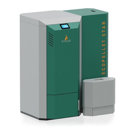
ECOPELLET STAR - CONDENS BOILER
Assembly and exploitation manual
Please read these instructions carefully before installing and/or lighting the appliance for the rst time.
Keep this document near the appliance, in a place which can easily be reached.
Advertisement

Subscribe to Our Youtube Channel
Related Manuals for Mareli Systems ECOPELLET STAR


Summary of Contents for Mareli Systems ECOPELLET STAR
- Page 1 Mareli Systems ECOPELLET STAR - CONDENS BOILER Assembly and exploitation manual Please read these instructions carefully before installing and/or lighting the appliance for the rst time. Keep this document near the appliance, in a place which can easily be reached.
-
Page 2: Safe Distances
ECOPELLET STAR boiler is below 50°C under condensation conditions. When the water temperature is between 30-50 C is when the boiler has it’s highest e ciency. As the water temperature gets higher the condensation e ect diminishes. - Page 3 Mareli Systems 1. PURPOSE e boiler is purposed to heat domestic and public premises by the means of pellets. e boiler is equipped with a steel water jacket designed for heating systems with water temperature up to 90º C at a maximum super pressure up to 0,15 Mpa. Tests are run at pressure of 0,3 Mpa.
-
Page 4: Technical Data
Mareli Systems 2. TECHNICAL DATA 383 mm 1132 mm 211 mm 746 mm 1133 mm 490 mm... - Page 5 Mareli Systems Pellet hopper Boiler body Exhaust fan Ash box Boiler burner...
- Page 6 Mareli Systems ф mm Φ6 Φ8 Φ6 Φ8 – A. Neighboring wall. e rear wall. C. Sidewall. D. Floor protection. E. Ignitable element. 1 = 50 (mm) 2 = 600 (mm) 3 = 400 (mm) 4 = 300 (mm) 5 = 1500 (mm)
- Page 7 Mareli Systems Exhaust Fan Condensation chamber cleaning mechanism Condensation chamber turbulators ermal isolation combustion chamber Combustion chamber spirals 9 Refractory plate combustion chamber Burning pot Combustion chamber temperature sensor External ash container Combustion chamber cleaning mechanism TOP 6 Condensation chamber water connection...
- Page 8 Mareli Systems 19 20 21 Touch screen display Combustion Fan Lambda regulation (Optional) Motor cleaning mechanism Burning pot Vacuum sensor 20 Auger Motor Combustion chamber cleaning mechanism Bottom Auger Motor return ame protection Motor cleaning mechanism TOP 17 Vacuum pump (Optional)
- Page 9 Mareli Systems 3. ASSEMBLY 3.1 General conditions. All national, regional and European requirements for safe operation of the appliance must be respected during installation and operation. Prior to installation, load capacity of the place where the boiler will be intended must be ensured.
- Page 10 Mareli Systems CHECK ITEMS BEFORE INSTALLATION Chimney exit Chimney Connection to chimney Connection to the boiler e chimney revision door Security distances Inlet air e oor...
- Page 11 • Chemical treatment of the circulating water is not recommended. “Mareli Systems” provides a warranty and out of warranty service and replacement of the water jackets. e warranty is not valid in case of a boiler with a swollen water jacket which is a result of pressure increase in the system and improper connecting.
- Page 12 Mareli Systems • Horizontal sections must have a minimum incline of 3° upwards; • e length of the horizontal sections must be as short as possible, but without exceeding 3 m; • More than four direction shi s are forbidden, including the cases where a T-shaped element is used;...
- Page 13 Mareli Systems 3.4 Types of connection to the chimney Chimney exit Moisture channel Chimney ermal insulation External wall Connection to chimney Flue gas connection Heat generator e chimney revision door “T” connection Attention!!! In order for the product to function e ciently the chimney must be built out of a...
- Page 14 3.6 VACUUM SENSOR e Vacuum sensor is installed on all the ECOPELLET STAR boiler. It’s main function is to regulate the air pressure in the combustion chamber. us, the optimal conditions for best combustion are re- spected and maintained.
- Page 15 Mareli Systems Combustion chamber cleaning mechanism for the Turbulators Condensation chamber cleaning mechanism for the Turbulators...
- Page 16 Mareli Systems Cleaning mechanism for the Burning pot Cleaning mechanism for the Ash chamber Motor cleaning mechanism for Ash chamber...
- Page 17 Mareli Systems PROCEDURE FOR SERVICING THE BURNING CHAMBER THERMAL INSULATION TOP DECORATION Remove the top decoration in order to access the top door of the burnning chamber.
- Page 18 Mareli Systems Remove the sensor for measuring the temperature inside the burn- ing chamber.
- Page 19 Mareli Systems Remove the 4 scrwos from each side of the combustion chamber door.
- Page 20 Mareli Systems User the 2 handles in the center to remove the combustion cham- ber door. Here you have access to the automatic cleaning mecha- nism for the turbulators.
- Page 21 Mareli Systems In order to access the main combustion chamber simply remove the inner-combustion chamber door.
- Page 22 Mareli Systems In case of maintenance you can remove the main combustion chamber by picking-up from the sides.
- Page 23 Mareli Systems In order to access the lower combustion chamber open the exteri- or decorative door.
- Page 24 Mareli Systems In order to access the lower combustion chamber open the interior door by pulling the lever in an upward manner.
- Page 25 Mareli Systems Remove the screw in order to free the combustion pot and it’s cleaning mechanism.
- Page 26 Mareli Systems Once the holding screw is removed the combustion pot unit can be easily accessed for maintenance.
- Page 27 Mareli Systems PROCEDURE FOR CLEANING THE ASH CONTAINER Pull the handle towards the right in order to free the ash container.
- Page 28 Mareli Systems Pull the ash container towards the le in order to detach it from the boiler.
- Page 29 Mareli Systems Pull the handle of the ash container to move it to an area dedicated for the ash disposal.
- Page 30 Mareli Systems Pull the lever on the side of the ash container it order to empty its content.
- Page 31 Mareli Systems PROCEDURE FOR ACCESSING THE CONDENSATION UNIT In order to gain access to the condenser unit you must remove the decorative cover. You can do this by pushing the cover upwards and then back.
- Page 32 Mareli Systems K400 TOUCH SCREEN DISPLAY 1. HOMEPAGE Date & Time Errors Code 11:24 Fri 14 Oct 2016 Er.01 21° Main Temperature IGNITION Functioning State 65° Main ermostat ON/OFF Settings Display Info Chrono...
- Page 33 Mareli Systems Main Commands In order to go to Homepage 2 a horizontal swipe must be performed to the right side of the screen. 12:18 Fri 14 Oct 2016 Er.01 Igniter Auger Pump 1 Pump 2 Aux1 Aux1 Aux3 Pump 3...
-
Page 34: Error List
Mareli Systems Quick visualization of the system main function 2. ERROR LIST 12:18 Fri 14 Oct 2016 Blocking or non-blocking error Er.01 21° is highlighted with a and the related error code. When pressed the error window opens IGNITION 65°... -
Page 35: Main Commands
Mareli Systems IGNITION Blocking / Removing Error 65° 4. MAIN COMMANDS 11:24 Ven 14 Ott 2016 Er.01 ON/OFF Menu Screen image : Swipe to Ignite • System power ON • System power OFF IGNITION • Alarms reset 65° 11:24 Ven 14 Ott 2016 Er.01... - Page 36 IGNITION Mareli Systems 65° 5. CHRONO 12:18 12:18 Ven 14 Ott 2016 Ven 14 Ott 2016 Er52 Er52 Chrono - Daily CHRONO 22° 22° 22° 22° 22° 22° 22° 22° 22° 22° 22° 22° 22° 22° 22° 22° 22° 22°...
- Page 37 Mareli Systems 5. INTERNAL MENU STRUCTURE From the display Menu the user can access the panel settings and select one of 24 languages Brightness. Minimum brightness: this function allows you to choose the minimum brightness level which the device automatically sets to a er 30 sec. of inactivity.
- Page 38 Mareli Systems Errors Er01 - Error Limit ermostat 1 (might signal even when the system is o ) Er02 - Error Limit ermostat 2 (might signal even when the system is o ) Er03 - Low Exhaust ue gas temperature or low ame Luminosity...
- Page 39 Mareli Systems DIAGRAM FOR ECOPELLET STAR SAFETY THERMOSTAT WATER POWER CABLE AUGER 1 PRESSURE SWITCH PROTECTION RETURN FLAME AUGER 2 ROOM THERMOSTAT IGNITER PUMP 1 WATER V-out PRESSURE PUMP 2 / VALVE SENSOR +12v ADDITIONAL V-out ENCODER CLEANING ENGINE 2...
- Page 40 Mareli Systems DIAGRAM LAMBDA BOARD PRIMARY VALVE SECONDERY VALVE...
- Page 42 MARELI SYSTEMS disclaims any responsibility for possible inaccuracies contained in this manu- al if they are due to printing or transcription errors. We reserve the right to make any change that appears to be necessary or useful without harm the essential characteristics.
Need help?
Do you have a question about the ECOPELLET STAR and is the answer not in the manual?
Questions and answers