Table of Contents
Advertisement
Quick Links
Advertisement
Table of Contents
Troubleshooting

Related Manuals for Endress+Hauser Analytik Jena CyBio Well vario


Summary of Contents for Endress+Hauser Analytik Jena CyBio Well vario
- Page 1 User Manual CyBio Well vario...
- Page 2 CyBio Well vario Copyright Copyright 2022 Analytik Jena GmbH. All rights reserved. No part of this documentation may be duplicated, photocopied, saved to a storage system or transferred to electronic media without prior written permission of the publisher. Publisher Analytik Jena GmbH Konrad-Zuse-Straße 1 07745 Jena, Germany Germany...
- Page 3 CyBio Well vario Rev B 2022/03...
- Page 4 CyBio Well vario EC Declaration of Conformity (reproduction of the content) Name and address of the manufacturer: Analytik Jena GmbH Konrad-Zuse-Straße 1 D-07745 Jena Herewith we declare, that the product described below CyBio Well vario OL3381-25-300 (linear system) OL3381-25-305 (linear system) OL3381-25-355 (round table) is complying with all corresponding requirements of the Machinery Directive 2006/42/EC.
- Page 5 CyBio Well vario Rev B 2022/03...
- Page 6 CyBio Well vario Rev B 2022/03...
- Page 7 CyBio Well vario Rev B 2022/03...
- Page 8 CyBio Well vario VIII Rev B 2022/03...
-
Page 9: Table Of Contents
CyBio Well vario Table of Contents General Information ................1 Notes on this User Manual ...................1 Intended Purpose ....................2 Conforming Use ....................2 Warranty & Liability ....................3 Scope of Delivery ....................4 Technical Specifications ................ 5 Safety Notes ..................11 General ....................... 11 Standards &... - Page 10 CyBio Well vario 4.5.1 Function With Pipetting Head................44 4.5.2 Function With Capillary Head ................45 Transportation & Storage ..............47 Transport ......................47 Storage ....................... 48 Initial Start-Up & Routine Start-Up Procedure ........49 Site requirements ....................49 6.1.1 Installation Requirements ..................
- Page 11 CyBio Well vario Accessories &Spare Parts ..............111 11.1 Pipetting Heads & Pipette Tips ............... 111 11.2 Capillary Magazines ..................112 11.3 Further Accessories ..................112 Waste Disposal ................. 115 12.1 Consumables ....................115 12.2 Reagents ......................115 12.3 System & Accessories ..................115 CyBio Well vario System .
- Page 12 CyBio Well vario Rev B 2022/03...
- Page 13 CyBio Well vario Table of Figures Fig. 1: Safety labeling at pipetting head and capillary head..... 14 Fig. 2: Safety labeling at compressed air control unit (only capillary head) ..14 Fig.
- Page 14 CyBio Well vario Fig. 50: Display screen – dispensing – dispensing volume ..... . 63 Fig. 51: Display screen – dispensing – aspiration volume ..... . 63 Fig.
- Page 15 CyBio Well vario Fig. 107: Insertion of magazine adapter (head replacement from the back version) ..... . . 84 Fig. 108: Display – head change – clamp magazine adapter ....84 Fig.
- Page 16 CyBio Well vario Rev B 2022/03...
-
Page 17: General Information
CyBio Well vario General Information General Information Notes on this User Manual This User Manual contains information regarding CyBio Well vario setup and function. It also provides qualified operator personnel with knowledge as required for the safe han- dling of the system, its components and related control and evaluation software module CyBio Composer. -
Page 18: Intended Purpose
General Information CyBio Well vario Intended Purpose The CyBio Well vario provides a simultaneous multi-pipetting tool for automated process- ing of microplates with 96, 384 or 1536 wells according to the SBS standard. Its basic functions are: dosing, pipetting, dispensing, diluting, rinsing, tip change and pipetting head replacement, as well as transportation of microplates. -
Page 19: Warranty & Liability
CyBio Well vario General Information caused by substances being examined. Process control must rely on included manufacturer software. Alterations in or damage to the software may give rise to faults in process and damage the system or its components. Software protection is the sole responsibility of the user. Warranty &... -
Page 20: Scope Of Delivery
General Information CyBio Well vario Scope of Delivery CyBio Well vario system delivery includes: CyBio Well vario Transporting unit (linear type or circular type) Pipetting head or capillary head Compressed air control unit (only for working with capillary head) ... -
Page 21: Technical Specifications
CyBio Well vario Technical Specifications Technical Specifications General characteristics Designation/type CyBio Well vario Airborne sound emission < 70 dB (A) Dimensional & weight details Width x height x depth (284 x 772.5 x 370) mm (without transporting unit) Width x height x depth (960 x 772.5 x 370) mm (with 3-place linear transporting unit) Width x height x depth... - Page 22 Technical Specifications CyBio Well vario Dosing volume of 96 piston pipetting head, Randomly selectable in steps of 0.01 μl 60 μl Precision for volume range of 2...3 μL Coefficient of variation ≤ 3 % Precision for volume range of 3...5 μL Coefficient of variation ≤...
- Page 23 CyBio Well vario Technical Specifications Dosing volume of 384 piston pipetting head, Randomly selectable in steps of 0.01 μl 2.5 μL Precision for volume range of 0.1...0.25 μl Coefficient of variation ≤ 7 % Precision for volume range of 0.25...0.5 μl Coefficient of variation ≤...
- Page 24 Technical Specifications CyBio Well vario Capillary head Intended use Parallel transfer of compounds and par- allel dispensing into dry microplates Aspiration by capillary force effect Dispensing by jet of compressed air Number of capillaries 96, 384 Material of capillaries Glass Volume range (fixed) 25 nl, 50 nl, 100 nl, 250 nl, 500 nl, 750 nl, 1000 nl...
- Page 25 CyBio Well vario Technical Specifications Operating Data Utility class stage unit, sealed and maintained rooms Permissible altitude up to 2000 m Protection class Internal protection standard IP 20 Interference suppression EN 55011 (DIN VDE 0875, Part 11) Limit value Class A Interference immunity EN 61000-6-2 Operating voltage...
- Page 26 Technical Specifications CyBio Well vario Rev B 2022/03...
-
Page 27: Safety Notes
CyBio Well vario Safety Notes Safety Notes General For your own safety and to ensure failsafe and reliable CyBio Well vario system opera- tion, you should carefully read this chapter before proceeding to any kind of start-up work! You are required to follow all safety notes that precede a description of work procedures in this Manual. -
Page 28: Symbols & Signal Words Used Throughout This Manual
Safety Notes CyBio Well vario Symbols & Signal Words Used Throughout This Manual To alert to potentially dangerous situations or provide useful advice, this User Manual uses the following symbols and signal words. Safety instructions are always placed before an action. - Page 29 CyBio Well vario Safety Notes Safety symbol Meaning Comment Warning of a Warns of mechanical hazard Hazard point from mechanically moving system parts Warns of dangerous electrical voltage Warns of hand injury Warns of crushing/pinching by mechanically moving parts Warning note Meaning Comment Warns of dangerous...
-
Page 30: Fig. 1: Safety Labeling At Pipetting Head And Capillary Head
Safety Notes CyBio Well vario Fig. 1: Safety labeling at pipetting head and capillary head Warning note "Weight" Warning note "Magazine adapter" Fig. 2: Safety labeling at compressed air control unit (only capillary head) Rev B 2022/03... -
Page 31: Mechanical Danger Zones
CyBio Well vario Safety Notes Head cover on system front on both sides in head area side with top cover open Rearside view of system Fig. 3: Safety labeling provided at the system Mechanical Danger Zones Fig. 4: Danger zones at pipettor Magazine clamping device Lifter Head cover... -
Page 32: Fig. 5: Danger Points At Transporting Unit
Safety Notes CyBio Well vario Fig. 5: Danger points at transporting unit Linear transporting unit: Circular transporting unit Motion of CyBio Well vario assemblies may create hazards to operating personnel. Failure to observe warning notes may result in pinching or crushing of one's hands. Any interven- tion performed with the system in operating state may cause damage to its hardware or to samples being processed. -
Page 33: General Safety Notes
CyBio Well vario Safety Notes General Safety Notes Do not analyze or use aggressive substances of a type that may compromise the stable Follow these general safety rules: performance of the system or its components (→ refer to page 21)! ... -
Page 34: Safety Requirements For Transportation & Installation
Safety Notes CyBio Well vario Safety Requirements for Transportation & Installation The system must be installed by service personnel of the manufacturer or duly trained and authorized expert personnel in all cases. Unauthorized assembly and installation is not permitted. Incorrect installation can create serious hazards. Follow these general safety rules: ... -
Page 35: 3.10.2 Compressed Air
CyBio Well vario Safety Notes 3.10.2 Compressed air Compressed air may prove a source of danger if operators are not familiar with the way it must be handled. For this reason, the system may not be operated by anyone other than qualified personnel. -
Page 36: 3.10.5 Maintenance & Care
Safety Notes CyBio Well vario 3.10.5 Maintenance & Care CyBio Well vario system maintenance may not be carried out by anyone other than ser- vice personnel of the manufacturer or duly authorized and properly trained expert tech- nicians. Unauthorized maintenance work may cause damage to the system. For this reason, operating personnel are not allowed to carry out work of any kind other than described in chapter "→... -
Page 37: 3.10.7 Chemical Resistance
CyBio Well vario Safety Notes 3.10.7 Chemical Resistance The manufacturer cannot be held liable if the operator of the device analyzes aggressive substances which may affect the durability of the components. Particular caution should be used when handling leaches, acids or organic solvents, because these may reduce the system's lifetime. -
Page 38: 3.11 Rules Of Conduct In Cases Of Emergency
Safety Notes CyBio Well vario 3.11 Rules of Conduct in Cases of Emergency In the event of a situation involving potential danger or danger of an accident, system power supply must be turned off at once, using the main power switch or the emer- gency pushbutton and/or by detaching the mains plug from the line socket! Since prompt reaction can save lives in a situation of danger, make sure that the following requirements are met:... -
Page 39: Technical Description
CyBio Well vario Technical Description Technical Description System Setup TheCyBio Well vario multi-channel pipettor is of modular design to facilitate different con- figurations for adaptation to a variety of customer applications. The system provides one essential advantage: only a few easy steps are required to replace the pipetting head or the capillary head with another head. -
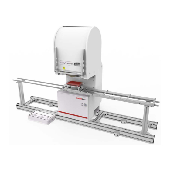
Page 40: Fig. 7: General View Of Cybio Well Vario
Technical Description CyBio Well vario The various functional units of the CyBio Well vario are shown in → Fig. 7 (version with linear transporting unit). Their functions are explained in the following chapters. Fig. 7: General view of CyBio Well vario (head replacement from the front version) Basic Unit Tip magazine... -
Page 41: Component Description
CyBio Well vario Technical Description Identification mark (model, serial number) Year of manufacture Information on the connection value label: Fuse Frequency, output Component Description 4.2.1 Basic Unit The basic unit contains four motors with functions as follows: ... -
Page 42: Operation Control Panel
Technical Description CyBio Well vario 4.2.2 Operation control panel The CyBio Well vario multi-channel pipettor may be connected to the operation control panel for working in manual mode. The various control panel elements are shown in → Fig. 9. Available functions are: ... -
Page 43: Pipetting Heads
CyBio Well vario Technical Description Cancel key [ESC] Aborts a running program for motion, aspiration, dispensing or tip change (clamping). On pressing [ENTER], the microplate carriage will move to position 1 in initial- ization mode When programming mode is currently set, this key will switch to the next highest menu level. -
Page 44: Fig. 10: Pipetting Head With Magazine Adapter
Technical Description CyBio Well vario Fig. 10: Pipetting head with magazine adapter Rail Handle Pipetting head Magazine adapter Rev B 2022/03... -
Page 45: Pipetting Head Cybio Well Vario 1536/8 Μl
CyBio Well vario Technical Description 4.2.4 Pipetting head CyBio Well vario 1536/8 μl Fig. 11: Pipetting head CyBio Well vario 1536/8 μl Pipetting head Serial number TipTray (1536, schematic diagram) Label Description Label/volume Material Drawing number Pos. 4, (Tips) → Abb. 11 Fixed TipTray (1) S 1 μl... -
Page 46: Capillary Head
Technical Description CyBio Well vario 4.2.5 Capillary Head The capillary head includes a magazine holder for capillary magazines. The clamping motor fixes a capillary magazine. The capillary head also provides a terminal for connec- tion of the air supply tube (→ see Fig. 12, → No. 5). A jet of compressed air is applied to completely dispense a previously aspirated amount of liquid into a microplate. -
Page 47: Tip Magazine (Pipetting Head)
CyBio Well vario Technical Description 4.2.6 Tip Magazine (Pipetting Head) A tip magazine holds 96 or 384 pipette tips. It maintains the pipette tips in an airtight- sealed condition while a pipetting process is going on. In the event of a pipetting head replacement or with major idle periods of the system, affected pipette tips must be kept in special tip tray packages. -
Page 48: Terminals
Technical Description CyBio Well vario 4.2.8 Terminals Located on the rear panel are the system terminals, interfaces and fuses (→ see Fig. 16). Warning notes must be observed in all cases and replaced immediately on noticing dam- age (→ see Fig. 15). Fig. -
Page 49: Compressed Air Control Unit
CyBio Well vario Technical Description 4.2.9 Compressed Air Control Unit For compressed air supply, oil-free compressed air of a maximum 5 bar pressure (0.5 MPa; 73 psi) must be available on site. The compressed air control unit is mechanically attached to the system frame. -
Page 50: Tip Wash Station 1536 Set
Technical Description CyBio Well vario Tip Wash Station 1536 Set 4.3.1 General The tip wash station consists of: wash tub with one inlet (green) and one outlet (red) suction tub Inlet and outlet are each realized via a peristaltic pump (e.g. via a TWS module). Wash tub The tube connections are shown in the overview (→... -
Page 51: Safety Notes
CyBio Well vario Technical Description Fig. 19: Suction tub Vacuum unit→ refer to page 36 Clear compressed air unit→ refer to page 33 Suction tub (OL5021-14-600) 4.3.3 Safety Notes The following safety symbols are affixed on the TWS module: Safety symbol Meaning Comment... -
Page 52: Component Description
Technical Description CyBio Well vario Do not place your hands or fingers, including objects you are holding, into the peristal- tic pump at any time during operation 4.3.4 Component Description Vacuum unit Fig. 22: Vacuum unit Vacuum generator Connections: SUP, EXH, VAC Bottle VAC connections Suction tub connections... -
Page 53: Fig. 23: Tws Module With 2 Peristaltic Pumps
CyBio Well vario Technical Description Fig. 23: TWS module with 2 peristaltic pumps TWS module Tube diagram Peristaltic pumps Tube Tube locks Lever NOTE Material damage due to aggressive acids and lyes as well as organic solvents! The tubes used in the peristaltic pumps come into direct contact with the liquid to be pumped. -
Page 54: Fig. 24: Tws Module - Connections (Rear Side)
Technical Description CyBio Well vario Fig. 24: TWS module – connections (rear side) Operating status indicator B 2 (BC) Output for connection of a barcode reader COM 1 Host PC COM 2 Main system (z. B. CyBio Well vario) COM 3 following device Power supply (PSPL) -
Page 55: Operation
CyBio Well vario Technical Description 4.3.5 Operation The TWS module and the tip wash station are controlled by the control software. The pumps can be controlled individually. When using the wash tub for the first time, place it in a liquid with low surface tension. This then ensures that all pipette tips are washed evenly. -
Page 56: Dabbing Station
Technical Description CyBio Well vario Dabbing station Observe the instructions for use (→ page 43) when using the dabbing station (OL5021-14-600)! 4.4.1 Introduction A pipetting cycle basically consists of aspirating the liquid into the tips, dispensing the liq- uid, ejecting the residual liquid and returning the pistons to the starting position (zero position). -
Page 57: Fig. 29: Typical Behavior Of The Residual Liquid In The Case Of
CyBio Well vario Technical Description Fig. 29: Typical behavior of the residual liquid in the case of small pipette tips and capillaries Tip in liquid after residual ejection Tip is moved out of liquid, residual liquid film remains Piston is moved to zero position; residual liquid is aspirated into pipette tip Liquid film remains in the pipette tip (and 6) Carryover in the next pipetting cycle Proper use of the dabbing station can prevent this carryover. -
Page 58: Functionality
Technical Description CyBio Well vario Fig. 30: Removing the residual liquid from the pipette tip Residual liquid in pipette tip or capillary Removal of residual liquid by gently pressing the pipette tips onto the fleece of the dabbing station during residual ejection Resetting the pistons to the zero position 4.4.2 Functionality... -
Page 59: Composers Scripts
CyBio Well vario Technical Description Fig. 31: Complete removal of the residual liquid from the pipette tips or capillaries by washing the dabbing fleece Residual liquid in pipette tip or capillary Removal of residual liquid by gently pressing the pipette tips onto the fleece of the dabbing station during residual ejection Tip with washing liquid Dispensing of the washing liquid (contact-free) onto the fleece and aspiration of the residual liq-... -
Page 60: Function
Technical Description CyBio Well vario After use, the dabbing station should be rinsed again with 30 to 50 ml of water. In addition, rinse with 30-50 ml of 70 % ethanol to prevent bacteria, etc. from multiplying in the moist environment. The use of the dabbing station can also be advisable for normal tips, especially if the liq- uids to be transferred tend to foam (e.g. -
Page 61: Function With Capillary Head
CyBio Well vario Technical Description Designed for high precision, including in the submicro liter volume range, and with great versatility, the CyBio Well vario covers a large range of applications. Through adaptation of the positioning system in XY-motion direction, all basic functions of a 96- channel simultaneously working system are also available for 384-channel microplates, using a four-step sequence, and for 1536-channel microplates, using a sixteen-step sequence. - Page 62 Technical Description CyBio Well vario Rev B 2022/03...
-
Page 63: Transportation & Storage
CyBio Well vario Transportation & Storage Transportation & Storage Transport CAUTION Environmental influences, mechanical shocks or formation of condensed water may destroy individual system components! Adequate precautions should be taken to protect all components from environmental impacts, mechanical shock or formation of condensed water during transportation or shipment! Temporary open-air storage of the system is prohibited! CAUTION Transportation with the pipetting head still in place is likely to cause damage to the pi-... -
Page 64: Storage
Transportation & Storage CyBio Well vario Storage If the CyBio Well vario is not installed immediately after arrival of product shipment or is not required for a longer period of time, it should preferentially be stored in its original packing case. Climatic requirements on facilities for system storage are as follows: ... -
Page 65: Initial Start-Up & Routine Start-Up Procedure
CyBio Well vario Initial Start-Up & Routine Start-Up Procedure Initial Start-Up & Routine Start-Up Procedure Site requirements 6.1.1 Installation Requirements The room which is selected for CyBio Well vario installation must meet the following envi- ronmental requirements: Temperature range:+15 °C to +35 °C ... -
Page 66: Power Supply
Initial Start-Up & Routine Start-Up Procedure CyBio Well vario 6.1.3 Power Supply WARNING If the grounding conductors are interrupted, there is risk of fatal injury due to electric shock! Never connect the mains plug of the device to a mains socket without a protective earth contact! Make sure that the protection effect is not rendered ineffective by extension cables without a PE conductor or by the use of a voltage regulating transformer! CAUTION... -
Page 67: Configuration & Start-Up
CyBio Well vario Initial Start-Up & Routine Start-Up Procedure Configuration & Start-Up In view of the complexity and to ensure failsafe system operation, work for installation and initial start-up of the CyBio Well vario on your premises is must be completely performed by customer service personnel of the manufacturer or duly authorized expert technicians. - Page 68 Initial Start-Up & Routine Start-Up Procedure CyBio Well vario CyBio Well vario CyBio Well vario CyBio Well vario CyBio Well vario 96-well/250 μL 96-well/ 40 μl/ 384-well/ 25 μl 96/384-well/60 μl 25 μl Aspiration volume 20 μl 10 μl 10 μl 10 μl Standard test vol- 10 μl...
- Page 69 CyBio Well vario Initial Start-Up & Routine Start-Up Procedure 1536 well (transparent flat-bottom) microplate prefilled with 0.1 N NaOH volumes as Materials & preparatory action: follows: 7 μl A certain inhomogeneity in the rate of evaporation over a microplate will influence the result of testing adversely.
-
Page 70: Accuracy Test
Initial Start-Up & Routine Start-Up Procedure CyBio Well vario 6.3.2 Accuracy Test Accuracy defines the degree to which a measured dispensed volume (mean value of all readings measured for a 96, 384 or a 1536 well microplate) is in agreement with a pre- defined (target) volume. -
Page 71: Leak Test
CyBio Well vario Initial Start-Up & Routine Start-Up Procedure 6.3.3 Leak Test Leak testing is required, in order to make sure that the pipettor head is free from points of leakage. Subject to testing are the pistons, the pipette tips and the silicon membrane. Testing is performed through aspiration of a certain volume of dye solution into the pipet- ting tips and visually tracking the level of liquid over a time of two hours (96 wells) or using a different procedure for 384 well pipetting heads, which is described further below. -
Page 72: Precision Test (Capillary Head)
Initial Start-Up & Routine Start-Up Procedure CyBio Well vario 6.3.4 Precision Test (Capillary Head) To perform precision testing, use the following procedure. To wet an inserted capillary magazine, use process settings as follows: Preparation: Rinse cycles: Rinsing liquid: Water Aspiration 8 sec. -
Page 73: Operation
CyBio Well vario Operation Operation Switching the CyBio Well vario on To switch the CyBio Well vario on, proceed as follows: Check that CyBio Well vario power cord is correctly connected to the line power supply point. For operation with a capillary head, check for proper setting of compressed air supply. Having installed the capillary head, connect the head's compressed air supply tube to its terminal point at the compressed air control unit Set the on/off switch on the front of the device (head replacement from the front ver-... -
Page 74: Fig. 34: Display Screen - Main Menu
Operation CyBio Well vario manual control mode, each of which provides further options for selection and execution of sub-programs and system functions (→ see Fig. 34 and → Fig. 35 respectively). Fig. 34: Display screen – main menu Fig. 35: Menu structure diagram view with pipetting head Select a menu or submenu using arrow key. -
Page 75: Menu [Manual]
CyBio Well vario Operation Hauptmenü Manuell Konfiguration Statistik Kopfwechsel Dispensieren Tischweg Gerätenr.: OL xxx Spitzenwechsel Kopfnr.: OL xxxx Wells Zyklen XY-Tisch: xxx Kolbenzyklen: xxx Tischgeschw. Gesamtvolumen [mL]: xx.xx Klick Kopfwechsel am Gerät: xx Gerätewechsel am Kopf: xx Kanalanzahl: xx Vers.: VX XX Fig. -
Page 76: Fig. 39: Display Screen - Dosing - Start
Operation CyBio Well vario Move a container with liquid into position under the tips (trough, microplate). Trigger carriage or rotary stage motion, using as necessary to reach the required position. To raise the lifter, use , to lower the lifter, use Note: With the lifter in raised position, you can set the following positions via 384X pipetting head:... -
Page 77: Fig. 41: Display Screen - Dosing - Dabbing Break
CyBio Well vario Operation Fig. 41: Display screen – dosing – dabbing break This basic function provides for aspiration of a greater volume of liquid, which is subse- Pipetting quently dispensed. This is followed by ejection of the residual volume. This procedure allows for higher accuracy, because there is no residue of liquid on the inner wall of a tip, which otherwise has to be taken into account. -
Page 78: Fig. 45: Display Screen - Pipetting - Aspiration Volume
Operation CyBio Well vario A preselected aspiration volume is aspirated in accordance with [pipetting] function settings. While dispensing lasts, the lifter and carriage (rotary stage) control unit remains inactive. Fig. 45: Display screen – pipetting – aspiration volume To pipette an aspirated volume of liquid, move a microplate into position under the tips. -
Page 79: Fig. 48: Display Screen - Pipetting - Dabbing Break
CyBio Well vario Operation 10. In a break for dabbing, you may use as necessary to position the tips more conveniently for dabbing. On termination of the dabbing break, the pistons will return to zero-position. Fig. 48: Display screen – pipetting – dabbing break Aspirates a total volume equal to the sum of all specified sub-volumes. -
Page 80: Fig. 52: Display - Dispensing - Start
Operation CyBio Well vario Move a container with dispensing stock into position under the tips (trough, micro- plate). Trigger carriage or rotary stage motion, using as necessary to reach the required position. To raise the lifter, use , to lower the lifter, use Note: With the lifter in raised position, you can set the following positions via 96X pipetting head:... -
Page 81: Fig. 54: Display Screen - Dispensing - Ejection
CyBio Well vario Operation Fig. 54: Display screen – dispensing – ejection Move a microplate into position under the tips for dispensing Trigger carriage or rotary stage motion, using as necessary to reach the required position. To raise the lifter, use , to lower the lifter, use 10. -
Page 82: Fig. 58: Display Screen - Diluting - Aspiration Volume
Operation CyBio Well vario Enter aspiration volume settings. Fig. 58: Display screen – diluting – aspiration volume Move a container with liquid into position under the tips (trough, microplate). Trigger carriage or rotary stage motion, using as necessary to reach the required position. -
Page 83: Fig. 61: Display Screen - Diluting - Ejection
CyBio Well vario Operation Move a microplate into position under the tips for ejection. Trigger carriage or rotary stage motion, using as necessary to reach the required position. To raise the lifter, use , to lower the lifter, use Note: With the lifter in raised position, you can set the following positions via 96X pipetting head: Motion to positions A1 to B2 for 384 well operation or... -
Page 84: Fig. 64: Display - Tip Change - Magazine Removal
Operation CyBio Well vario Fig. 64: Display – tip change – magazine removal Fig. 65: Tip magazine change (for head replacement from the front) Magazine plate Pipette tips CAUTION There is danger of piston or system damage! Remember that only tip-filled magazines may be inserted and clamped! Insertion of a magazine is monitored by a microswitch. -
Page 85: Fig. 67: Display - Tip Change - Tightening Of Tips
CyBio Well vario Operation Fig. 67: Display – tip change – tightening of tips Aspirates or dispenses a specified volume of rinsing liquid in a defined order of rinsing Purging cycles. Enter a value for the number of rinsing cycles (maximum: 20). Fig. -
Page 86: Fig. 72: Display Screen - Rinsing - Dispensing
Operation CyBio Well vario Fig. 72: Display screen – rinsing - dispensing In a break for dabbing, you may use as necessary to posi- tion the tips more conveniently for dabbing. On termination of the dabbing break, the pistons will return to zero-position. Fig. -
Page 87: Fig. 76: Display - Dispense With Position Selection
CyBio Well vario Operation Trigger carriage or rotary stage motion, using as necessary to reach the required position. To raise the lifter, use , to lower the lifter, use You should also note the following: If a 96-channel capillary magazine has been inserted, a positional shift must be included for 384-well or 1536-well processing. -
Page 88: Fig. 78: Display - Tip Change - Tip Release
Operation CyBio Well vario Confirm your selection by pressing , in order to trigger a dispensing cycle. The previously aspirated volume is dispensed again. While dispensing lasts, the lifter and carriage (rotary stage) control unit remains inactive. Tip replacement CAUTION There is danger of finger pinching and damage to capillary tips! The magazine plate is released and clamped with electro-motoric power. -
Page 89: Fig. 81: Display - Tip Change - Magazine Insertion
CyBio Well vario Operation CAUTION Prevent damage to the system! Only capillary-filled magazines may be inserted and clamped! Insertion of a magazine is mon- itored by a microswitch. If a magazine is placed in a non-conforming manner, an "Insert mag- azine (with tips)"... -
Page 90: Menu [Configuration]
Operation CyBio Well vario 7.2.3 Menu [Configuration] Pipettor settings can be adapted to specific user or application requirements. This can be Pipetting head achieved via the [Configuration] menu: Restores the main menu should the pipettor be working in a different submenu. Use key in the main menu to select the [Configuration] submenu. -
Page 91: Fig. 84: A1 Well Target Positions For 96/384/1536 Well Microplate
CyBio Well vario Operation Fig. 84: A1 well target positions for 96/384/1536 well microplate A1 well target position for 96 well microplate A1 well target position for 384 well microplate A1 well target position for 1536 well microplate The diagram view illustrates that the tips will come down onto the edge of wells in the case of a faulty plate type setting. -
Page 92: Fig. 86: Display - Configuration Menu (Capillary Head)
Operation CyBio Well vario CAUTION With excessively high settings for carriage motion or rotary stage motion, there may be overflow of liquid from the reagent troughs. Select a reasonably reduced speed value if necessary. In manual mode, lifter motion is limited to a maximum speed of 17 mm/s (60 rpm). This is necessary to enable a more precise height setting. -
Page 93: Fig. 87: A1 Well Target Positions For 96/384/1536 Well Microplate
CyBio Well vario Operation the middle of its companion well. Fig. 87: A1 well target positions for 96/384/1536 well microplate A1 well target position for 96 well microplate A1 well target position for 384 well microplate A1 well target position for 1536 well microplate The diagram view illustrates that the tips will come down onto the edge of wells in the case of a faulty plate type setting. -
Page 94: Menu [Head Change]
Operation CyBio Well vario Allows you to set an acoustic click for confirmation of each keystroke. You can switch the Click click on and off. 7.2.4 Menu [Head change] Replacement of the pipetting head or the capillary head can be performed in the [Head change] menu. -
Page 95: Fig. 91: Remove Tip Magazine Or Capillary Magazine
CyBio Well vario Operation Fig. 91: Remove tip magazine or capillary magazine (head replacement from the front version) Use recessed handle to push the magazine adapter down into the pipetting head until mechanical stop position. Fig. 92: Display – head change – insert magazine adapter Fig. -
Page 96: Fig. 95: Display - Head Change - Remove Head Please
Operation CyBio Well vario Fig. 95: Display – head change – remove head please CAUTION There is danger of crushing or pinching as the cover is opened or closed! To open or close the cover, hold it at the handle with one hand! Keep the other hand clear of the system space! Hold the handle of the head cover with one hand, then tilt cover up until it engages mechanically. -
Page 97: Fig. 97: Retrieval Of Pipetting Head (From The Front Head Replacement Version)
CyBio Well vario Operation Fig. 97: Retrieval of pipetting head (from the front head replacement version) Handle Recessed handle at adapter bottom To insert a new pipetting head or capillary head, proceed as follows: Hold pipetting head at its handle with one hand. Use the other hand for support as you push the pipetting head in. -
Page 98: Fig. 99: Display - Head Change - Remove Magazine Adapter
Operation CyBio Well vario CAUTION Risk of crushing! To open or close the cover, hold its handle with one hand! Keep the other hand clear of the system space. Tilt cover down until it closes, then release cover. The cover locks by itself. The magazine adapter moves down and unlocks auto- ... -
Page 99: Fig. 102: Pushing Magazine In (Head Replacement From The Front Version)
CyBio Well vario Operation Fig. 102: Pushing magazine in (head replacement from the front version) 12. Confirm tip magazine clamped state by pressing key Head replacement is complete. The system is ready again for operation. To perform head replacement for "from the back” version, proceed as follows: Head replacement from the back Press key in the main menu as necessary to select the [Head change]... -
Page 100: Fig. 105: Removal Of Tip Magazine (Head Replacement From The Back Version)
Operation CyBio Well vario Fig. 105: Removal of tip magazine (head replacement from the back version) Use recessed handle to push the magazine adapter down into the pipetting head until mechanical stop position. Fig. 106: Display – head change – insert magazine adapter Fig. -
Page 101: Fig. 109: Display - Head Change - Remove Head
CyBio Well vario Operation Wait until prompt for removal of head appears, then confirm by pressing key Fig. 109: Display – head change – remove head CAUTION There is danger of crushing or pinching as the cover is opened or closed! To open or close the cover, hold it at the handle with one hand! Keep the other hand clear of the system space! Hold the handle at the back of the head cover with one hand, then tilt cover up until... -
Page 102: Fig. 111: Removal Of Pipetting Head (Head Replacement From The Back Version)
Operation CyBio Well vario Fig. 111: Removal of pipetting head (head replacement from the back version) To insert a new pipetting head, proceed as follows: Hold pipetting head at its handle with one hand. Use the other hand for support as you push the pipetting head in. Note: Use recessed handle at magazine adapter bottom for this purpose. -
Page 103: Fig. 113: Display - Head Change - Remove Magazine Adapter
CyBio Well vario Operation 10. Pull magazine adapter out of pipetting head from the front. Use recessed handle at magazine adapter bottom for this purpose. Fig. 113: Display – head change – remove magazine adapter Fig. 114: Removal of magazine adapter (head replacement from the back version) CAUTION There is danger of piston or system damage! -
Page 104: Special Functions
Operation CyBio Well vario Fig. 116: Insertion of tip magazine (head replacement from the back version) 12. Confirm tip magazine clamped state by pressing key Head replacement is complete. The system is ready again for operation. 7.2.5 Special functions CAUTION There is danger of damage to the system due to incorrect parameter settings, following a reset of operating parameters! - Page 105 CyBio Well vario Operation Resets all operating parameters Button Resets all system parameters, including drive parameters, to manufacturer values. On pressing of this key, the following system parameters must be set manually again. Drive parameters Are valid for powering of the pump motor (piston drive), the carriage (rotary stage) motor and the lifter motor: •...
-
Page 106: Switching The Cybio Well Vario Off
Operation CyBio Well vario Switching the CyBio Well vario off To switch the CyBio Well vario off, proceed as follows: Pipetting head Wait until the CyBio Well vario has completed all work operations. Use the main switch to switch the CyBio Well vario off. Close CyBio Composer control software session if necessary and switch the PC off. -
Page 107: Specific System Details (Pipetting Head)
CyBio Well vario Operation Specific System Details (Pipetting Head) Aspiration and dispensing of liquid is accomplished by piston motion. All piston suspension points have a mechanical freeplay (slackness). This means: After each reversal in piston motion direction, the piston drive initially covers a certain travel length without actually moving the pistons, and, hence, without aspirating or dispensing any liquid. -
Page 108: Aspiration Without Additional Stroke
Operation CyBio Well vario dispensed with additional stroke (5) into a waste box or the reservoir. Since the stroke length is greater than actually required for the residual volume (D3), the residual volume is completely dispensed. Finally, the amount of air is dispensed (D4). A volume cycle is com- pleted by "Motion into zero-position". -
Page 109: Volume Cycle
CyBio Well vario Operation 7.4.3 Volume Cycle Aspiration with additional stroke Standard cycle: Dispensing (single volume or subvolumes) Residual dispensing Motion to zero-position Aspiration without additional stroke Simplified cycle (only for dispensing of single volumes): ... -
Page 110: System Precision (Pipetting Head)
Operation CyBio Well vario System Precision (Pipetting Head) The CyBio Well vario works based on the principle of air displacement. This means that 96 or 384 pistons, which are mechanically connected with a common drive, perform motion in 96 or 384 air spaces created by the pipette tips and internal seals. The volume resolution capability of piston motion corresponds to one tenth, one hundredth or one thousandth of a micro liter. -
Page 111: Troubleshooting
CyBio Well vario Troubleshooting Troubleshooting Malfunction or faults during operation will be displayed on the working screen. Where a fault situation was clearly caused by operator action, operation can be resumed, once the fault has been removed (switch power off and on again for greater safety). Check all potential fault sources on occurrence of a fault. - Page 112 Troubleshooting CyBio Well vario Error/error code Cause Remedy The lifter cannot find its internal Switch power supply off and on lower zero position. again. Note: On repeated occurrence of this fault, repair work is necessary! Error by external device, Switch power supply off and on again.
- Page 113 CyBio Well vario Troubleshooting In addition, the following faults may occur: Error message Cause Remedy No aspiration allowed at The system tries to aspirate Correct program sequence this point. a volume, following an aspi- as necessary. ration or a dispensing cycle, despite the fact that the pis- tons have not yet returned to their zero-positions.
- Page 114 Troubleshooting CyBio Well vario Error message Cause Remedy No residual ejection After aspiration of a vol- Ad a [Dispense with addi- ume, there was no residual tional stroke] command at ejection of dosing stock dur- the appropriate point in a ing the remaining program sequence.
- Page 115 CyBio Well vario Troubleshooting Error message Cause Remedy Illegal command Transfer cables are in a Check transfer cables for non-conforming state. proper condition. Software version not config- Check that available soft- ured for your system. ware version is actually con- figured for your system (refer to Hardware system information window in...
- Page 116 Troubleshooting CyBio Well vario Error message Cause Remedy Text too long Text which is intended for Shorten output text. output to the system display is too long. stage reached upper end stage motion has reached Use keyboard at the CyBio position its upper end position.
-
Page 117: Errors By Compressed Air Control Unit (Capillary Head)
CyBio Well vario Troubleshooting Errors By Compressed Air Control Unit (Capillary Head) Error Cause Remedy Fixed opening clogged. Replace component or fixed No pressure at output. opening (customer service). Dust in sealing part of main Remove dust from valve seat Compressed air leakage valve by replacement of seat com-... - Page 118 Troubleshooting CyBio Well vario Rev B 2022/03...
-
Page 119: Maintenance & Care
CyBio Well vario Maintenance & Care Maintenance & Care Safety Notes WARNING Note that contact with voltage-carrying system parts may lead to physical injury or even death! Switch system power off and detach power cable from the line socket before you pro- ceed to any kind of maintenance or care! Make sure that the system is protected from accidental restoration of power! Operating personnel are prohibited from performing work for maintenance, repair or... -
Page 120: Maintenance Work
Maintenance & Care CyBio Well vario Maintenance Work 9.2.1 Overview The following table lists required maintenance and care work items with related periodici- ties. Maintenance Action Maintenance interval Weekly Monthly Every six months Clean transport rails with carriage or rotary stage Use mild cleaning agent or disinfectant to clean the tip wash trough... -
Page 121: Lubricating Transport Rails (Linear Transporting Unit)
CyBio Well vario Maintenance & Care The piston sealing components are subject to strong wear and tear, conditional upon the number of motion cycles completed. Typically, their service life exceeds 250 000 cycles. For this specification, it is assumed that pistons and seals are free from contamination. Dirt, e.g. -
Page 122: Fig. 119: Toolset
Maintenance & Care CyBio Well vario Fig. 119: Toolset Allen key for replacement of capillaries Special tool for adjustment of glass tips Replacing capillaries in capillary magazine CAUTION Glass capillaries are fragile! There is danger of physical injury from glass splinters! Proceed with adequate caution when replacing a capillary cassette or individual capil- laries! Keep capillary magazines always in the storage box. -
Page 123: Cleaning The Carriage (Linear Transporting Unit)
CyBio Well vario Maintenance & Care 9.2.6 Cleaning the Carriage (Linear Transporting Unit) Carriage performance depends on the current state of the transport rails. Remove pock- ets of dirt, contamination or damage of transport rails immediately. To clean the carriage, proceed as follows: Switch CyBio Well vario power off at the main power switch, then disconnect the power plug from the socket. -
Page 124: Compressed Air Control Unit - Draining Condensate
Maintenance & Care CyBio Well vario Do not remount the tips, until the sealing mat has fully dried. 9.2.9 Compressed Air Control Unit – Draining Condensate CAUTION Danger! Splashing! When draining condensate, hold a piece of cloth underneath the drain screw. Regularly check the view glass at the compressed air control unit for condensate level. -
Page 125: Decommissioning
CyBio Well vario Decommissioning Decommissioning CAUTION There is danger of injury and damage to the pipettor if cables are removed before pow- er is switched off! Do not remove cables as long as they are energized! Make absolutely certain that power supply has been cut before you remove a cable! If the CyBio Well vario is not required for a longer period of time, perform shut-down action as described hereafter:... - Page 126 Decommissioning CyBio Well vario Rev B 2022/03...
-
Page 127: Accessories &Spare Parts
CyBio Well vario Accessories &Spare Parts Accessories &Spare Parts 11.1 Pipetting Heads & Pipette Tips The pipettor and its accessories are factory-matched to each other. Use only accesso- ries recommended by the manufacturer. The manufacturer will refuse any warranty in the event of damage or function failure as a result of system operation with unspecified accessory items. -
Page 128: 11.2 Capillary Magazines
Accessories &Spare Parts CyBio Well vario For more detailed information about available Pipette tips and magazines, you should consult our latest catalog or visit us on the Internet. 11.2 Capillary Magazines 96-channel and 384-channel capillary magazines, including 10 reserve capillaries 25 nl capillary magazine 50 nl capillary magazine 100 nl capillary magazine... - Page 129 CyBio Well vario Accessories &Spare Parts Pipetting head CyBio Well vario 1536/8 μl Consumables Description Volume Material Ordering code Label (Tips) number Fixed TipTray (1) 1 μl steel OL5021-25-588 Fixed TipTray (2) 8 μl Glass OL5021-25-585 Re-Fill TipTray 8 μl OL5021-25-511 1 In case.
- Page 130 Accessories &Spare Parts CyBio Well vario Rev B 2022/03...
-
Page 131: Waste Disposal
CyBio Well vario Waste Disposal Waste Disposal 12.1 Consumables ENVIRONMENTAL PROTECTION Consumable materials must be disposed in accordance with binding workplace safety and environmental provisions of law. 12.2 Reagents ENVIRONMENTAL PROTECTION Biological samples must be treated in accordance with locally binding regulations for the handling of infectious material. - Page 132 Waste Disposal CyBio Well vario Rev B 2022/03...
-
Page 133: A 1 Cybio Well Vario System
CyBio Well vario A 1 CyBio Well vario System NOTE This User Manual Supplement provides an overview of the CyBio Well vario system as a whole. It is only valid if used in combination with CyBio Well vario and Stacker User Manuals. For specific information regarding the various modules, you are referred to the relevant descriptions in CyBio Well vario (→... -
Page 134: A 1.2Technical Specifications
CyBio Well vario A 1.2Technical Specifications For specific performance details of the various modules, you are referred to the appro- priate user manuals of the CyBio Well vario (→ refer to chapter 2 ) and the stacker. A 1.2.1Phys. Dimensions & Weight Details of CyBio Well vario System With 2 Stackers CAUTION The system is designed as a desk-top device. -
Page 135: A 1.3Safety Notes
CyBio Well vario A 1.3Safety Notes You are also advised to follow all safety notes (→ refer to chapter 3 ) in the CyBio Well vario User Manual and the Stacker User Manual. Fig. 123: Warning notes and safety devices Stop-and-Down pushbutton for Warning label at pipetting head stacker... -
Page 136: A 1.4Device Versions
CyBio Well vario A 1.4Device Versions Possible combinations are: Name Quantity Number of stack- CyBio Well vario Stacker — CyBio Well vario CyBio Well vario — stacker Stacker — CyBio Well vario — stacker EXT — system A 1.4.1Setup Versions Possible setup versions are: ... -
Page 137: A 1.5Installation & Startup Procedures
CyBio Well vario A 1.5Installation & Startup Procedures Work for installation and initial start-up of the CyBio Well vario system may not be performed by anyone other than service personnel of the manufacturer or that of specifically authorized contractors. A 1.5.1Cabling Diagram Fig. -
Page 138: Fig. 127: Direction Of Rotation And Delivery Of Liquid
CyBio Well vario A 1.5.2Tubing The pump for reservoir filling is located at the stacker. The pump's direction of rotation Reservoir filling station determines the direction in which liquid will be transported (→ Fig. 127). Fig. 127: Direction of rotation and delivery of liquid for peristaltic pump at the stacker "Fill"... -
Page 139: A 1.6Operation
CyBio Well vario A 1.6Operation A 1.6.1Operating Modes The following operating modes are available when working with a CyBio Well vario system: Working with manual control unit (→ refer to chapter 7.2 ): Manual mode Configuration Statistics PC-controlled operation (refer to Plugin Pipettor Software ManualCyBio Composer) A 1.6.2PC Mode Data transfers between the CyBio Well vario, stackers, additional modules and the control PC interface... -
Page 140: A 1.7Maintenance & Care
CyBio Well vario Pin assignments at the CyBio Well vario Fig. 130: Pin assignments of 9-pole D-Sub jack (CyBio Well vario) Pin assignments at stacker Fig. 131: Pin assignments of 9-pole D-Sub jack (stacker) A 1.7Maintenance & Care All advisory notes (→ refer to chapter 9 ) in the CyBio Well vario User Manual and the Stacker User Manual have unrestricted validity and must be followed. - Page 141 CyBio Well vario Error/Error code Cause Remedy System fails to work Mains plug not properly Insert mains power plug despite availability of connected to mains socket correctly. power supply, display or the system's combi-seal. remains dark. Mains socket is de-ener- Use other mains socket.
- Page 142 CyBio Well vario Rev B 2022/03...
-
Page 143: A 2 Scripts
CyBio Well vario A 2 Scripts The following exemplary scripts illustrate the handling of the dabbing station Move to dab location Switch on vacuum Move to dab height (tips have contact with the fleece) Residual ejection with blowout Waiting time Remove tips from the fleece Waiting time Contact/dab again... -
Page 144: Fig. 133: Example 2
CyBio Well vario Move to dab location Switch on vacuum Move the dabbing station very close to fleece – no contact Ejection of the nominal volume (i.e. the volume taken up) Waiting time Contact with fleece Residual ejection with blowout Waiting time Remove tips from the fleece Waiting time... -
Page 145: Fig. 134: Example 3
CyBio Well vario It may happen that after dabbing or even while dabbing on the wet fleece, a thin film of liquid remains / forms on the tips. In this case, it is necessary to burst this film with an increased additional volume/blowout. - Page 146 CyBio Well vario Rev B 2022/03...
- Page 147 CyBio Well vario Index Index Symbols Delivery of liquid 122 Detergent 53 "Fill" command 122 Device versions 120 Menu 74 Diluting 44 Dimensions 118 Accessories 111 Direction of rotation 122 Additional stroke 91 Dispensing 44 Air humidity 49 Dispensing with additional stroke Arrow keys 26 Aspiration with additional stroke Dosing 44...
- Page 148 Index CyBio Well vario Jet of compressed air 45 Safety notes 119 Scope of delivery 4 Sealing plate 107 Linear transporting Serial number II unit 23 Setup versions 120 Site requirements 49 Maintenance 124 Solenoid valve 33 Maintenance & care 103 Source plate 45 Maintenance action 104 Spare parts 111...
- Page 149 CyBio Well vario Index Tube sensor 34 Tubing 122 TWS module Connections 38 Danger areas 35 Operation 36 Vacuum extraction 33 Ventilation devices 18 Volume cycle 93 Volumes 27 Waiting Time 74 Waiting time 93 Warranty & liability 3 Wash tub Technical specifications 39 Washing liquid 34 Waste disposal 115...
- Page 150 CyBio Well vario Rev B 2022/03...
Need help?
Do you have a question about the Analytik Jena CyBio Well vario and is the answer not in the manual?
Questions and answers