Table of Contents
Advertisement
Quick Links
Advertisement
Table of Contents

Related Manuals for Trilux LiveLink LightGrid


Summary of Contents for Trilux LiveLink LightGrid
- Page 1 LIVELINK LIGHTGRID...
-
Page 2: Table Of Contents
BEDIENELEMENTE ................................... 5 2.1.2.1 TASTER ..................................5 2.1.2.2 TOUCHPANEL ................................5 2.1.3 SENSOREN ....................................6 2.1.3.1 LIVELINK LIGHTGRID SENSOR HF ..........................6 2.1.3.2 LIVELINK LIGHTGRID SENSOR PIR ..........................7 2.1.3.3 SENSOR-PLATZIERUNG .............................. 7 2.1.3.4 VERHALTEN DER LICHTSTEUERUNG IM BETRIEB..................... 9 2.1.4 WAS IST HUMAN CENTRIC LIGHTING (HCL)? ........................ -
Page 3: Einleitung
• Work with electrical devices must only be carried out with discon- • LiveLink LightGrid is not intended for any application other than nected power supply. those specified here. Other applications are considered improper. -
Page 4: System Und Funktionen
EN 61547 EN 41347-1 EN 41347-11 EN 55032 EN 55024 DALI cable length max. 300 m Cable length of push-buttons max. 25 m Permissible cable cross-section 0,5 - 1.5mm2 7896500 Controller for the LiveLink LightGrid system: LiveLink LightGrid Controller DB.tif T_10257638_37111_DB.tif... -
Page 5: Bedienelemente
They are inte- Radio range 10 m grated via QR code scanning in the LiveLink LightGrid app. Up to 4 ra- Protection rating IP20 dio buttons can be integrated into one luminaire group. Mounting is by... -
Page 6: Sensoren
The sensor is highly compact and blends harmoniously into the ceiling design thanks to its discreet appearance. In conjunction with the LiveLink LightGrid Controller, the sensor is used to detect mo- tion and changes of light. The sensor is connected to the controller via a separately orderable RJ10 cable. -
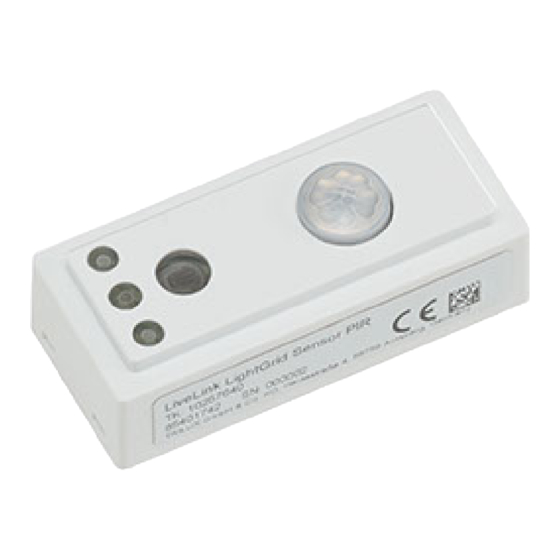
Page 7: Livelink Lightgrid Sensor Pir
The sensor is highly compact and blends harmoniously into the ceiling design thanks to its discreet appearance. In conjunc- tion with the LiveLink LightGrid Controller, the sensor is used to detect changes in movement of light. The sensor is connected to the controller via a separately orderable RJ10 cable. - Page 8 SYSTEM AND FUNCTIONS Daylight-dependent control It is important for the function of daylight-dependent control that light sensors or combined presence and light sensors are positioned in suit- able locations. The sensor should be positioned in the area of the visual task.
-
Page 9: Verhalten Der Lichtsteuerung Im Betrieb
SYSTEM AND FUNCTIONS 2.1.3.4 BEHAVIOUR OF THE LIGHT CONTROL DURING OPERATION The behaviour of the light control in operation is defined during com- • Automatic switch-off of all luminaire groups by the presence de- missioning with the Install app. For this purpose, a default lighting tection (upon expiry of the switch-off delay or inverse time) results scene is defined which is activated when the lighting is switched on in an automatic recall of the default light scene. -
Page 10: Was Ist Human Centric Lighting (Hcl)
If the HCL function is activated in a light scene, this "circadian" progression is automatically called up when the lighting is switched on. The reference for TRILUX is always natural daylight with its colour tem- The preset daytime sequence refers to the location. -
Page 11: Smart Connect Leuchten
Through in- tegration into the LiveLink LightGrid system, control via app, push-but- ton or touch panel is also possible. LiveLink LightGrid luminaires are identified by the marking "+SMC" (Smart Connect). Luminaire for a LiveLink LightGrid system:... -
Page 12: Luceo
The luminaires are parameterised via the LiveLink LightGrid app. Manual adjustment of the light colour and separate switching and dimming of both light components is possi- Luminaire for a LiveLink LightGrid system: ble via three illuminated controls. -
Page 13: Bedienung Und Betrieb
SYSTEM AND FUNCTIONS CONTROL AND OPERATION The LiveLink LightGrid light control system can be operated manually In addition, the app can be used to make extensive adjustments to the during operation with (wireless) push-buttons, touch panels or on the system's default settings defined during commissioning (see "Practical luminaires themselves. -
Page 14: Systemplanung
SYSTEM AND FUNCTIONS SYSTEM PLANNING 2.3.1 STAND-ALONE In stand-alone mode, up to twelve Smart Connect luminaires can be ated fully or semi-automatically via tablet or radio button. The LiveLink interconnected, which creates a Bluetooth mesh network. Within this LightGrid app and a Bluetooth-capable tablet or smartphone are re- network, all sensors of the luminaires function as control units, ena- quired for commissioning. -
Page 15: Hybrid System
The system can be operated fully or semi-automatically via tablet, further 32 DALI devices. These are centrally managed by the controller, (wireless) push-button or touch panel. The LiveLink LightGrid app and which is counted as one wireless device. By integrating the controller, a Bluetooth-capable tablet or smartphone are required for commis- Bluetooth touch panels can be added to the system. -
Page 16: Hardware Reset
SECURITY 8 | 38 10251146 | 220714 | © TRILUX.com © TRILUX.com | 220714 | 10251146 Bluetooth Low Energy (BLE) security takes place. If further devices are added to a group, these devices are When the app connects to the BLE device, it creates a network ID key also assigned the same network ID and key. -
Page 17: Inbetriebnahme
COMMISSIONING 3 COMMISSIONING APP USE The LiveLink LightGrid app is used to configure luminaire groups, sen- Note: sor functions, general lighting and push-buttons. The respective set- Before opening the LiveLink LightGrid app, make sure the Bluetooth tings can be individually adjusted in the app. -
Page 18: Legende Symbole
COMMISSIONING 3.1.3 LEGEND ICONS Settings Scan QR code Settings (error / problem detected) Search Close / cancel Automatic mode Switch on luminaire Confirm / save changes Switch-off time enabled Back Flash disabled Illuminance Movement detected Edit Update Colour temperature HCL-curve enabled Take photo Caution Delete... -
Page 19: Anwendung
3.1.4 APPLICATION 3.1.4.1 LAUNCHING THE APP Launching the LiveLink "LightGrid" app The LiveLink LightGrid app is started by tapping the app icon. 3.1.4.2 CONNECTING DEVICES Connect device After opening the LiveLink LightGrid app, a window is displayed in which you can search for devices. The search can be a manual search (magnifying glass icon) or by scanning a QR code (QR code icon). -
Page 20: Geräte Profil Bearbeiten
COMMISSIONING Select new devices As soon as the password is confirmed during the manual search, all luminaires subject to this password and within radio range are dis- played. By tapping the luminaire symbol, the respective luminaire can be identified in the room. Tap the respective luminaires to select them. A tick appears for the selected luminaires as confirmation. - Page 21 COMMISSIONING Edit connection If editing of a connected device is selected, a new window opens with the following information: • Luminaire serial number • Luminaire photo • Image or photo of the luminaire The following settings can also be made: •...
-
Page 22: Verbindungsaufbau
Tap the tick symbol at bottom right to save the changes made. Tap the tick to confirm the saving process. 3.1.4.4 CONNECTION SETUP Connect device By tapping the respective luminaire, the LiveLink LightGrid app con- nects to the selected device. -
Page 23: Einstellungsoptionen
COMMISSIONING Device menu The device menu displays the following setting options: • Enable / disable display mode • Enable network control • Settings • Automatic mode • Presets • Colour temperature control • Switch luminaire on/off • Dimming level 3.1.4.5 SETTING OPTIONS Settings Tapping the settings icon opens the following setting options:... - Page 24 COMMISSIONING Notes and problems Tap on the setting option "Notes and problems" to edit these. This op- tion only appears if there are indications or problems. Edit notes and problems This setting option lists existing notes and problems. Tapping on the tick confirms that any notes and problems have been noted.
- Page 25 COMMISSIONING Set clock Tap the setting option "Set clock" to individually set the time. Note: After selecting the setting option "Set clock" for the first time, your agreement will be requested once for use of the location (GPS). This is necessary to determine the HCL-curve suitable for the location.
- Page 26 COMMISSIONING Settings – Cultega In the "Settings" area, only the following parameters can be managed for Cultega luminaires due to lack of sensors: • Status after Power ON • MDT (motion detector) mode • Direct MDT (motion detector) switch-off time in minutes Note: The motion detector settings refer to the sensor values of the control- ler.
- Page 27 COMMISSIONING Status after Power ON For the "Status after Power ON" parameter, the following options can be selected: Setting options Switches luminaire off ON AUTO Switches on automatic mode ON MANUAL Switches on manual mode ON SCENE 1 Switches on Scene 1 ON SCENE 2 Switches on Scene 2 ON SCENE 3...
- Page 28 COMMISSIONING Indirect MDT (motion detector) sensitivity The "Indirect MDT (motion detector) sensitivity" parameter sets the sensitivity of the motion detector for the indirect light. The following options are available: Setting options Motion detector sensitivity of 1% Motion detector sensitivity of Motion detector sensitivity of Motion detector sensitivity of Motion detector sensitivity of...
- Page 29 COMMISSIONING Indirect MDT (motion detector) switch-off time in minutes The "Indirect MDT (motion detector) switch-off time in minutes" pa- rameter defines the time after which the motion detector switches off the indirect light in the absence of movement. The following options are available: Setting options 1 minute...
- Page 30 COMMISSIONING Light detector The "Light detector" parameter enables the light sensor for daylight control. The following options are available: Setting options do not use The light detector is disabled used The light detector is enabled 230V push-button 1 With the "230V push-button 1" parameter, a function can be assigned to the push-button input T1 on the controller.
- Page 31 COMMISSIONING HCL demo Tap the "HCL demo" setting option to call up a demo of the HCL-curve. HCL demo In the "HCL demo" setting option, the HCL-curve adjusted to the loca- tion is displayed. The following detail information is displayed: •...
- Page 32 COMMISSIONING Extended device info of the luminaire The "Device info" setting option displays the following extended device information: • Hardware • Light sensor L=current light value/R=reference value (unit: bit) • Light setpoint L=current light value/R=reference value (unit: bit) • MDT (motion detector) indirect (icon is displayed when movement or presence is detected) •...
- Page 33 COMMISSIONING Transfer project After scanning the QR code, the settings stored on the QR code are transferred to the device. The name of the settings is displayed in green letters DALI ECG programming With a DT6 variant of the controller, the DALI ECGs (electronic control gear units) must be assigned.
- Page 34 COMMISSIONING Search DALI EVG After the password has been confirmed, all available ECGs connected to the controller are searched for. Note: If there are more than three ECGs (electronic control gear units), this procedure must also be carried out. DALI ECG group programming As soon as all control gear units have been located, the system actu- ates them one after the other (visual feedback by flashing).
- Page 35 COMMISSIONING Radio button overview In the radio button overview, up to four fourfold radio buttons can be integrated by scanning a QR code. Tapping the QR code icon opens the camera for scanning. Note: The four radio buttons are automatically assigned preset functions af- ter scanning (see: Radio button overview –...
- Page 36 COMMISSIONING Radio push-button 1 - setting options (preset) Button upper left (fourfold push-button only) Room ON AUTO MAX Button bottom left (fourfold push-button only) Group OFF BWM (motion sensor) - ON ready Button upper right ON AUTO MAX Button bottom right Room OFF Radio push-button 2 - setting options (preset) Button upper left (fourfold push-button only)
- Page 37 COMMISSIONING Calibrate light sensor Tap the "Calibrate light sensor" setting option to calibrate the light sen- sor. Calibration of the light sensor Illuminance can be managed in the light sensor calibration area. For proper calibration, the luxmeter must be placed in the centre of the work area and the room should be darkened so that there is no daylight.
- Page 38 COMMISSIONING RESET factory settings Tap the "RESET factory settings" setting option to reset the connected device to delivery state. This does not include the device password. Reset luminaire to factory settings By tapping the tick, the connected device can be reset to the factory settings.
- Page 39 COMMISSIONING Mesh network With the "Mesh network" parameter, the following options for the mesh network can be selected: Setting options The luminaire is not integrated in the mesh network The luminaire is integrated in the mesh network ON + APP local scenes The luminaire is integrated in the mesh network and the local scenes (pre-configured,...
- Page 40 COMMISSIONING Swarm mode With the "Swarm mode" parameter, the functional range of the swarm mode can be defined. The following options are available: Setting options Motion sensor disabled ON room (only luminaires in the Swarm mode activated: all vicinity) luminaires in the room that are within the reception range of the luminaire are actuated.
- Page 41 COMMISSIONING Swarm HCL-Curve type The "Swarm HCL-curve type" parameter can be used to select which variables are to be influenced when running the HCL-curve. The follow- ing options are available: Setting options colour temperature only When the HCL-curve is run, only the colour temperature of the lighting is adjusted according to time of day / position of sun...
- Page 42 COMMISSIONING Network settings – devices in vicinity After the search for devices in vicinity has been started (with the mag- nifying glass icon), an overview opens which lists all devices found. In addition, the network or group in which they are currently located and the signal strength are displayed (blue bar).
- Page 43 COMMISSIONING Touch controls luminaire The "Touch controls luminaire" parameter enables selection of which luminaires are to be controlled by the touch panel. The following op- tions are available: Setting options whole room All devices assigned to the room are controlled by the touch panel Group 1 All devices assigned to group 1 are controlled by the touch panel...
- Page 44 The CO2 sensors are currently not included as standard with the Live- Link LightGrid system. If you have any questions regarding the integra- tion and use of these sensors, please contact the LMS Light Manage- ment Support of Trilux (lms@trilux.com). The following options are available: Setting options...
- Page 45 COMMISSIONING Help Tap the "Help" setting to access the system manual of the LiveLink LightGrid system. Imprint / data security Tap the "Imprint / data security" setting to access the company infor- mation and Trilux data security regulation.
-
Page 46: Anhang
APPENDIX 4 APPENDIX SETTING OPTIONS 4.1.1 230V PUSH-BUTTON INPUT 230V push-button input do not use no function Pulse: MANUAL <-> OFF Switch manual mode on and off by push-button pulse Pulse: AUTO <-> OFF Switch automatic mode on and off by push-button pulse Pulse: ->... - Page 47 APPENDIX Pulse: my scene 1 group Push-button pulse enables self-defined scene 1 of the group Pulse: my scene 2 group Push-button pulse enables self-defined scene 2 of the group Pulse: my scene 3 group Push-button pulse enables self-defined scene 3 of the group Pulse: my scene 4 group Push-button pulse enables self-defined scene 4 of the group Pulse: my scene 1 room...
-
Page 48: Funktaster
APPENDIX Test function, used for internal and external tests (to test customer request functions before inclusion in scope of functions) Test function, used for internal and external tests (to test customer request functions before inclusion in scope of functions) Test function, used for internal and external tests (to test customer request functions before inclusion in scope of functions) Test function, used for internal and external tests (to test customer request functions before inclusion in scope of functions) - Page 49 APPENDIX Group ON SCENE 4 Switch on group with scene 4 Group colour AUTO Enable HCL sequence in automatic mode in the group Group colour MANUAL Enable HCL sequence in manual mode in the group Group OFF + disable motion sensor Switch off group and disable motion sensor Group ON SCENE 1 + disable motion sensor Switch on group with scene 1 + motion sensor is disabled...
- Page 50 APPENDIX CCT increase Increase colour temperature (cool) CCT dim down Decrease colour temperature (warm) Indirect ON AUTO MAX Switch on automatic mode of indirect light component Automatic HCL-curve + light control GROUP indirect ON AUTO MAX Switch on automatic mode of indirect light component of group Automatic HCL-curve + light control ROOM indirect ON AUTO MAX Switch on automatic mode of indirect light component of room Automatic HCL-curve + light...
- Page 51 TRILUX GmbH & Co. KG Postbox 1960 · 59753 Arnsberg, Germany Tel. +49 (0) 29 32.301-0 Fax +49 (0) 29 32.301-375 info@trilux.de · www.trilux.de...
Need help?
Do you have a question about the LiveLink LightGrid and is the answer not in the manual?
Questions and answers