Table of Contents
Advertisement
Quick Links
ONDECK
™
INSTALLATION INSTRUCTIONS
Important Safety Information
WARNING
Failure to follow these warnings, cautions, and notices could result in personal injury, damage to the vessel or
device, or poor product performance.
See the Important Safety and Product Information guide in the product box for product warnings and other
important information.
When connecting the power cable, do not remove the in-line fuse holder. To prevent the possibility of injury or
product damage caused by fire or overheating, the appropriate fuse must be in place as indicated in the product
specifications. Connecting the power cable without the appropriate fuse in place voids the product warranty.
CAUTION
To avoid possible personal injury, always wear safety goggles, ear protection, and a dust mask when drilling,
cutting, or sanding.
To avoid possible personal injury or damage to the device and vessel, disconnect the vessel's power supply
before beginning to install the device.
To avoid possible personal injury or damage to the device or vessel, before applying power to the device, make
sure that it has been properly grounded, following the instructions in the guide.
To avoid possible personal injury or damage to this device and vessel, only install this device when the vessel is
on land, or when properly secured and docked in calm water conditions.
NOTICE
For the best possible performance, the device must be installed according to these instructions.
When drilling or cutting, always check what is on the opposite side of the surface to avoid damaging the vessel.
Read all installation instructions before proceeding with the installation. If you experience difficulty during the
installation, contact Garmin
Product Support.
®
Contacting Garmin Support
• Go to
support.garmin.com
for help and information, such as product manuals, frequently asked questions,
videos, and customer support.
• In the USA, call 913-397-8200 or 1-800-800-1020.
• In the UK, call 0808 238 0000.
• In Europe, call +44 (0) 870 850 1241.
November 2022
GUID-6AED2D91-1EED-4702-BB7B-92D845BF82D6 v8
Advertisement
Table of Contents

Subscribe to Our Youtube Channel
Related Manuals for Garmin ONDECK GTB 10


Summary of Contents for Garmin ONDECK GTB 10
- Page 1 When drilling or cutting, always check what is on the opposite side of the surface to avoid damaging the vessel. Read all installation instructions before proceeding with the installation. If you experience difficulty during the installation, contact Garmin Product Support.
-
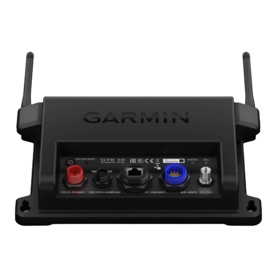
Page 2: Connector View
Power cable connection NMEA 2000 NMEA 2000 network ® NETWORK Garmin Marine Network IN/OUT Connects relays and wired sensors, such as temperature, security, and shore power Connects to an external GPS antenna Tools Needed • Drill • Drill bits appropriate for the surface and hardware •... -
Page 3: Mounting Considerations
Mounting Considerations NOTICE This device should be mounted in a location that is not exposed to extreme temperatures or conditions. The temperature range for this device is listed in the product specifications (GTB 10 Specifications, page 19). Extended exposure to temperatures exceeding the specified temperature range, in storage or operating conditions, may cause device failure. -
Page 4: Installing The Antennas
8 Repeat these steps to install the second antenna. Connection Considerations When connecting this device to power and to other Garmin devices, you should observe these considerations. • You must check the power and ground connections to the battery to make sure they are secured and cannot become loose. -
Page 5: Connecting To Power
Connecting to Power WARNING When connecting the power cable, do not remove the in-line fuse holder. To prevent the possibility of injury or product damage caused by fire or overheating, the appropriate fuse must be in place as indicated in the product specifications. - Page 6 Power Cable Extensions If necessary, the power cable can be extended using the appropriate wire gauge for the length of the extension. Splice • Up to 4.6 m (15 ft.): 10 AWG (5.26 mm ) extension wire • Up to 7 m (23 ft.): 8 AWG (8.36 mm ) extension wire •...
-
Page 7: Connection Diagram
Connection Diagram Garmin chartplotter connected to the Garmin Marine Network and NMEA 2000 network GTB 10 black box device Sensor connected through the NMEA 2000 network GPS antenna with a BNC connector (sold separately and required only if the internal GPS antenna... - Page 8 IN/OUT Cable Pinout WARNING All connections should be made using proper electrical connectors. To avoid the potential for electric shock and damage to equipment, ensure connections are watertight if they will be exposed to moisture.
- Page 9 Do not connect these wires to the positive side of a power source. This relay is automatically controlled by the GTB 10 black box device to switch power to Garmin Marine Network devices. This relay is automatically controlled by the GTB 10 black box device to switch power to NMEA 2000 devices.
- Page 10 • You should install a 1 Amp fuse on all relay controls, Boat-in-Use, Bilge 1/2, and Battery 1/2 inputs at the positive input to the power source. • The Boat-in-Use, Bilge 1/2, and Battery 1/2 inputs require a voltage between 10 and 32 Vdc. •...
- Page 11 You can use an external relay switch to turn on and off an item, such as a light, on your vessel remotely, using the ActiveCaptain app. One 12 V relay is included. If you need more relays or 24 V relays, they are available separately for purchase at garmin.com. NOTICE To avoid potential damage to the relay switch, GTB 10 black box device, and device being switched, you must install this relay switch in a dry location.
- Page 12 ) wire. NOTICE You must connect the Boat-in-Use input so that it receives power when you turn on your Garmin marine devices, including Garmin chartplotters. If you do not connect the Boat-in-Use input, the device may not remain in a full-power state like other Garmin devices, which prevents you from connecting the device to the vessel Wi‑Fi...
- Page 13 Garmin devices, including the devices not properly turning off or the software becoming inoperable. This device can connect to additional Garmin Marine Network devices to share data and update the software from a connected Garmin chartplotter. When connecting Garmin Marine Network devices to this device, observe these considerations.
- Page 14 To avoid potential damage to the relay switch, GTB 10 black box device, and device being switched, you must install this relay switch in a dry location. This relay is automatically controlled by the GTB 10 black box device to switch power to Garmin Marine Network devices.
- Page 15 2000 network. If you do not have an existing NMEA 2000 network you can create a basic NMEA 2000 network using cables and connectors available from your Garmin dealer. If you will only be monitoring part of your NMEA 2000 network remotely with the OnDeck system, you must...
- Page 16 Optional switch for GTB 10 power (must be turned on for remote operation) Ignition or in-line switch for the NMEA 2000 network Power source NMEA 2000 compatible Garmin device NMEA 2000 drop cable NMEA 2000 power cable NMEA 2000 male terminator or backbone cable extension...
- Page 18 GTB 10 black box device GTB 10 black box power cable GTB 10 IN/OUT cable, Relay 7 (NMEA 2000), blue wire Optional switch for GTB 10 power (must be turned on for remote operation) NMEA 2000 power relay (one 12 V relay included) NMEA 2000 device, connected to the section of the NMEA 2000 network unaffected by the relay Power source NMEA 2000 device, connected to the section of the NMEA 2000 network affected by the relay...
- Page 19 From -50° to 105°C (from -58° to 221°F) Security Sensor Specifications Operating temperature range From -15° to 80°C (from 5° to 176°F) The device withstands incidental exposure to water of up to 1 m for up to 30 min. For more information, go to www.garmin.com/waterrating.
-
Page 20: Device Dimensions
12 V Relay Switch Specifications Operating temperature range From -15° to 85°C (from 5° to 185°F) Storage temperature range From -40° to 155°C (from -40° to 311°F) Control voltage (coil) 7.8 to 15.6 Vdc Load power min. (contacts) 0.1 A Up to 15 A at 10 to 16 Vdc Load power max. - Page 21 Wireless Protocols and Frequencies Protocol Frequency range Typical power UMTS low 824 to 915 Mhz -6.4 dBm UMTS mid 1710 to 1980 Mhz 20.8 dBm LTE FDD low 1 699 to 787 Mhz 21.8 dBm LTE FDD low 2 814 to 862 Mhz 24.1 dBm LTE FDD low 3 880 to 915 Mhz 20.4 dBm LTE FDD mid 1...
-
Page 22: Nmea 2000 Pgn Information
NMEA 2000 PGN Information Transmit and Receive Description 059392 ISO acknowledgment 059904 ISO request 060160 ISO transport protocol: Data transfer 060416 ISO transport protocol: Connection management 060928 ISO address claim 126208 Request group function 126993 Heartbeat 126996 Product information Transmit Description 126464 Transmit and receive PGN list group function... - Page 23 This radio transmitter, 1792A-03675, has been approved by Innovation, Science and Economic Development Canada to operate only with the antennas provided by Garmin, which have an impedance of 50 ohms and a maximum gain of 3.1 dBi. Other antennas may have a gain greater than the maximum gain of the approved antennas, and are strictly prohibited for use with this device.
- Page 24 © 2020 Garmin Ltd. or its subsidiaries support.garmin.com...
Need help?
Do you have a question about the ONDECK GTB 10 and is the answer not in the manual?
Questions and answers