CEMB N330 User Manual
Rotors balancer – single and double plane portable vibrometer spectrum analyzer
Hide thumbs
Also See for N330:
- Quick manual (12 pages) ,
- Quick manual (16 pages) ,
- Quick manual (20 pages)

Related Manuals for CEMB N330


Summary of Contents for CEMB N330
- Page 1 Via Risorgimento, 9 23826 – Mandello del Lario (LC) – ITALY www.cemb.com N330 ROTORS BALANCER – SINGLE AND DOUBLE PLANE PORTABLE VIBROMETER SPECTRUM ANALYZER USER MANUAL Rev. 03/2021 EN Translation of the original instructions...
- Page 3 Index N330 rev. 03/2021 EN Chapter 1 - General description Standard accessories................1 – 1 Optional accessories ................1 – 3 Connections ..................... 1 – 4 Input A and B (vibration sensor – BLUE and RED inputs) ......1 – 5 ...
- Page 4 Measure setup ..........……………………………5 – 3 Take screenshot..........……………………………5 – 3 Chapter 6 - FFT mode – Fast Fourier Transform Spectral analysis (FFT) – measurement screen ......... …….6 – 1 Measurement of a FFT spectra ..........…………….6 – 2 ...
- Page 5 “CBA” – measurement screen ........... ……………………9 – 2 Measurement of a “CBA” value ............……9 – 2 CEMB limits / custom limits ............... ……9 – 3 MENU function ..........……………………………………9 – 5 Save measure ..........……………………………9 – 5 ...
- Page 6 Angular components ........ ……………………………11 – 16 Balancing report ........……………………………11 – 17 Warnings on Permissible Unbalance accordingly to ISO 21940-11……11 – 19 Chapter 12 - “TACHO” mode “TACHO” – measurement screen ........……………………12 – 1 Measure of a “TACHO”...
- Page 7 Appendix A - Technical data Appendix B - Judgment criteria on industrial machines (ISO 10816) Appendix C - Judgment criteria on machine tool spindles (ISO 17243) Appendix D - A rapid guide to interpreting a spectrum Appendix E - Photocell for instruments Nx30 Appendix F - The JSON format Appendix G - Balancing accuracy of rigid rotors Index...
- Page 8 Empty page Index...
- Page 9 Chapter 1 General description The N330 instrument is supplied, together with its accessories, in a special case. It is advisable, each time the instrument is used, to place back it in its case in order to avoid risk of damage during transit.
- Page 10 No.1 probe Photocell complete with stand and magnetic base Roll of reflecting paper No.1 angle rule No.1 micro USB cable No.1 battery charger with multiplug adapters No.1 HEAVY DUTY carrying case No.1 USB key containing instruction manual in PDF format "Quick Guide"...
- Page 11 Optional accessories: DESCRIZIONE Connection cable, length 5 meters, for accelerometer Extension cable, length 10 meters, for transducer/photocell No. 1 accelerometer transducer 100mV/g additional No.1 connection cable, length 2 meters, for accelerometer additional No.1 magnetic base Ø 25 mm additional No.1 probe additional General description 1 - 3...
- Page 12 Connections 1. battery charger 2. micro USB port (useful for connecting the instrument to a PC and sharing a folder for the exchange of data between the two elements) 3. connector for photocell input (YELLOW connector) 4. connector for sensor input – channel A (BLUE connector) 5.
- Page 13 Input A and B (vibration sensors – BLUE and RED inputs) CONNECTOR PINOUT 1 – GROUND + SHIELDING (SIG-) 2 – SENSOR INPUT (SIG+) 3 – SENSOR POWER SUPPLY) Input TACHO (photocell sensor – YELLOW input) CONNECTOR PINOUT 1 – +24 VDC 5 –...
- Page 14 Battery The N330 instrument is provided with a built-in rechargeable lithium battery, which allows autonomy of more than 8 hours under normal operating conditions of the instrument. The battery status is indicated by an icon in the upper right hand corner of the screen.
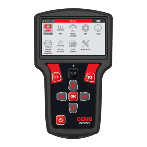
- Page 15 Chapter 2 General layout Keys/buttons available on the control panel The control panel of the CEMB N330 instrument incorporates a keypad where the various keys or buttons can be subdivided by function: ON/OFF button Press this button to switch the instrument on; hold it down for at least 3 seconds to switch it off , then release the button.
- Page 16 Caution: In case the instrument no longer responds to any command, it can be turned off by keeping the button pressed for about 12 seconds. OK button Pressing this button in a setup screen confirms the settings selected, and allows switching to the next screen.
- Page 17 Screen description battery charge level (see 1-5 Battery) measure/function type date and time sensor sensitivity set on Setup Sensors (see 13-2 Sensor sensitivity "A" / Sensor sensitivity "B") measurement channel displayed (the symbols recall the color of the displayed channel – see 1.4 Connections) main screen content - graphical representation of the measurement information/indications on the measure function corresponding to the F1 key...
- Page 18 Empty page 2 - 4 General layout...
- Page 19 Chapter 3 Home screen (menu) After fully switching on the N330 instrument, it shows its Home screen. which, besides showing a set of information as: current date and time battery charge state as a normal menu, it also proposes and allows selection of the available functionality, namely:...
- Page 20 BALANCING static and dynamic balancing data management (load or delete the data saved on LOAD MEASURE instrument N330) setting of the sensors connected to the instrument setting of the general measurement parameters SETUP setting of the general operating parameters of the...
- Page 21 Chapter 4 OVERALL vibrometer mode One of the simplest, but at the same time most significant information in vibration analysis, is the overall value of the actual vibration. In fact, this is very often the first parameter to be considered when evaluating the operating conditions of a motor, fan, pump, machine tool. Appropriate tables allow discrimination between an optimum state and a good state, or from an allowable, tolerable, non-permissible or even a dangerous one.
- Page 22 Press to start the measurement; the instrument acquires continuously, press again freeze the acquisition. Note: The measurement unit, the unit mode and the frequency range are set using the MEASURE SETUP function (see Setup mode 13-1), freely modifiable using the specific function or the command menu.
- Page 23 MENU function Access to the menu using the key . The following functionalities are available here: Save measure Allows the data saving in a determined project of the detected measurement (see Function "Save measure" 14-1). Open measure Allows the opening of a certain measure previously acquired through the VIBROMETER mode and saved in a specific project (see Function "Open measure"...
- Page 24 Empty page 4 - 4 OVERALL vibrometer mode...
- Page 25 Chapter 5 1xRPM vibrometer mode In certain situations instead, it could be interesting to know the values of modulus and phase of the synchronous vibration (1xRPM), i.e. corresponding to the speed of rotation of the rotor. The vibrometer mode is designed to make this type of measure. 1xRPM Vibrometer (filtered measure) –...
- Page 26 (0°). Starting from this position, the angles are measured in the opposite direction to the shaft rotation (see appendix E - Photocells for instruments CEMB Nx30). 5 - 2...
- Page 27 MENU function Access to the menu using the key . The following functionalities are available here: Save measure Allows the data saving in a determined project of the detected measurement (see Function "Save measure" 14-1). Open measure Allows the opening of a certain measure previously acquired through the VIBROMETER mode and saved in a specific project (see Function "Open measure"...
- Page 28 Empty page 5 - 4 1xRPM vibrometer mode...
- Page 29 Chapter 6 FFT mode – Fast Fourier Transform A complete analysis of the vibration cannot fail to take into account the study of the various factors contributing towards forming its overall value. Hence it is essential to be able to carry out spectrum analysis with FFT (Fast Fourier Transform) algorithm.
- Page 30 Measurement of a FFT spectra Select the FFT mode from the main page of the instrument by pressing the key At the first access to the function after switching on the instrument, if no measurement has been performed yet, an alarm reminds to connect the sensors before making the measurement.
- Page 31 Management of the X-Y axis of the graph After the measurement, the data is plotted on the graph in AUTOSCALE mode (axis limits in line with the data in the graph). The zoom of the X axis can be managed by pressing the keys , while the keys determine the zoom of the Y axis.
- Page 32 A box in the upper right corner indicates the amplitude and frequency values of the peak highlighted by the cursor. The keys moves the cursor to another peak in a frequency of interest. Moving the cursor will automatically update the box containing the amplitude and frequency information of the highlighted peak.
- Page 33 Peak list This MENU item shows a table with a maximum of 10 peaks of higher amplitude, associated to the corresponding frequency. The peaks value is calculated by applying an interpolation algorithm to the graph, and this allows to identify the exact value of the frequency of the individual peaks regardless of the number of lines selected (see Measure setup –...
- Page 34 Empty page 6 - 6 FFT mode – Fast Fourier Transform...
- Page 35 Chapter 7 “SMART ANALYSIS” mode This functionality should be considered as a simple and fast method for the evaluation of vibrations on standard type rotating machines. The function, according to the international standards ISO 20816-1 and ISO 10816-3 (Evaluation of machine vibration by measurements on non-rotating parts), measures the velocity of vibration expressed in mm/s RMS and within the frequency range 10÷1000 Hz.
- Page 36 Setting the type of machine to be analyzed Select the SMART ANALYSIS mode from the main page of the instrument by pressing the key At the first access to the function after switching on the instrument, a setup procedure is accessed.
- Page 37 STEP 2: setting the foundation type Select from the following possibilities: RIGID FLEXIBLE Note: Move between the choices available using the keys Confirm each setup step using the key Return to the previous step using (BACK). Note: This setup is set only when the function is first accessed.
- Page 38 Setup “CUSTOM SMART ANALYSIS” Select the item “CUSTOM SMART ANALYSIS”. Confirm the choice using the key Choose the CUSTOM MACHINE from the available list. Press the keys to choose and select the previously created machines, press to confirm. Note: Move between the choices available using the keys Confirm each setup step using the key Note: This setup is set only when the function is first accessed.
- Page 39 The rotation speed is acquired through the use of the photocell sensor. Note: The use of the photocell needs to applying a reflecting plate on the impeller as a reference mark (see appendix D - Photocells for CEMB Nx30 instruments). Manual entry The rotation speed data is entered manually.
- Page 40 Move in the numeric keypad using the “arrows keys”. Confirm each individual digit by pressing . At the end of the procedure press (NEXT) to confirm. Note: Check the rotation speed by consulting the plate data or the operating manual of the machine under analysis. ...
- Page 41 Note: This setup is set only when the function is first accessed. By exiting and accessing it again the previously setup is retained. To change it, refer to the item CHANGE SPEED DETECTION SETUP available in the function MENU. Detection of a "SMART ANALYSIS" measure After the setups shown on the previous pages or after having accessed the function again, press to start the measurement;...
- Page 42 MENU function Access to the menu using the key . The following functionalities are available here: Save measure Allows the data saving in a determined project of the detected measurement (see Function "Save measure" 14-1). Open measure Allows the opening of a certain measure previously acquired through the SMART ANALYSIS mode and saved in a specific project (see Function "Open measure"...
- Page 43 Chapter 8 “SPINDLE ANALYSIS” mode This functionality should be considered as a simple and fast method for the evaluation of machine tool spindles vibrations by measuring on spindle housing. The function follows the criteria of the following regulations: ISO 17243-1 (spindles with rolling element bearing and integral drives operating at speeds between 600 and 30,000 RPM) ...
- Page 44 Setting the type of spindle to be analyzed Select the SPINDLE ANALYSIS mode from the main page of the instrument by pressing the key At the first access to the function after switching on the instrument, a setup procedure is accessed.
- Page 45 The rotation speed is acquired through the use of the photocell sensor. Note: The use of the photocell needs to applying a reference marker on the impeller as a reference mark (see appendix E - Photocells for CEMB Nx30 instruments). “SPINDLE ANALYSIS” mode...
- Page 46 Manual entry The rotation speed data is entered manually. Move in the numeric keypad using the “arrows keys”. Confirm each individual digit by pressing . At the end of the procedure press (NEXT) to confirm. Note: Check the rotation speed by consulting the plate data or the operating manual of the machine under analysis.
- Page 47 Select the peak of interest with the keys ; press to confirm. Note: This setup is set only when the function is first accessed. By exiting and accessing it again the previously setup is retained. To change it, refer to the item CHANGE SPINDLE SETUP available in the function MENU.
- Page 48 Note: The sensitivity set for the sensor in use is shown in the upper right area of the display. To change its value, see 13-2 Sensor “A” Sensitivity / Sensor “B” Sensitivity. Note: With measurement from channel “B” enabled (see 13-2 Sensor “B”), the key changes the channel shown on the display, switching from channel “A”...
- Page 49 MENU function Access to the menu using the key . The following functionalities are available here: Save measure Allows the data saving in a determined project of the detected measurement (see Function "Save measure" 14-1). Open measure Allows the opening of a certain measure previously acquired through the SMART ANALYSIS mode and saved in a specific project (see Function "Open measure"...
- Page 50 Empty page 8 - 8 “SPINDLE ANALYSIS” mode...
- Page 51 A correct way to measure bearing condition is the envelope of the acceleration signal acquired in a high frequency range. CEMB has developed this CBA function (CEMB BEARING ANALYSIS), measured in gE (acceleration g calculate with an envelope algorithm). Note:...
- Page 52 “CBA” – measurement screen The measurement page supplies a series of information, organized as shown in the figure: 1. displayed measurement channel 2. “CBA” value detected Measurement of a “CBA” value Select the CBA mode from the main page of the instrument by pressing the key At the first access to the function after switching on the instrument, if no measurement has been performed yet, an alarm reminds to connect the sensors before making the measurement.
- Page 53 TOLERABLE 5 ÷ 10 gE UNACCEPTABLE 10+ gE As a standard configuration, the function provides judgment limits coming from CEMB experience and know-how, to be understood as guidelines for assessing the severity of the measured value. “CBA” mode 9 - 3...
- Page 54 The user can set custom thresholds by choosing on the function menu (key ) the item "ACTIVATE CUSTOM LIMITS". Will appear a screen that allows the setup of the A/B and B/C thresholds, linked to the measurement judgment criteria. Select the parameter of interest using the keys ;...
- Page 55 Note: The user can switch to the CEMB DEFAULT LIMITS by choosing the item BACK TO CEMB DEFAULT LIMITS from the MENU Confirm the choice with the key MENU function Access to the menu using the key . The following functionalities are available here: ...
- Page 56 Activate custom limits / Back to CEMB default limits Allows to activate/deactivate custom limits for the evaluation of the severity of the measured value (see CEMB limits / custom limits 9-3). 9 - 6 “CBA” mode...
- Page 57 Chapter 10 Grinding wheel balancer mode The N330 instrument has a practical function for balancing in situ of grinding wheels, using a vibration sensor and a photocell. The instrument is able to balance grinding wheels with no.2 or no.3 sliding weights through a simple procedure, which guides the operator step by step along the sequence of operations.
- Page 58 Function access menu The selection of the function shows to the operator a page where to select the following options: 1. New program 2. Open project 3. Delete project 4. Use current program (available only if a program previously created has been completed until the balancing correction is calculated) New project –...
- Page 59 Setting of the grinding wheel rotation direction Choose from the following options: CLOCKWISE COUNTER CLOCKWISE Note: Move between the available choices using the and keys Confirm each setup step using the key Back to the previous step with (BACK).
- Page 60 Note: On the "Final Report" screen, the (BACK) key backs to the main menu of the balancing mode, while the key (TAKE SCREENSHOT) takes a screenshot of the display, saving it as a .png file (see Function "Take screenshot" 14-4). Delete project Allows to individually delete the balancing projects saved in the instrument.
- Page 61 Use current project Resume the balancing program previously created and completed (calibration procedure completed and calculation of the balancing correction). Caution: Switching off the device causes the loss of unsaved data (and therefore also of the current project); this option is therefore not initially available for a new instrument switch-on;...
- Page 62 Note: Use the key (NEXT) to go to the next vibration acquisition screen. In case key is pressed incorrectly, a warning indicates the exact procedure to follow. Move the sliding weights as required, at the first startup of the instrument, if no measurement of this type has been performed yet, a warning message reminds to connect the sensors before making the measurement itself.
- Page 63 The higher is the level of the bars, the better will be the quality of the measurement (which is averaged over time). After reaching the required level, stop the measurement again by pressing Note: Unstable signals produce measures whose quality fails to reach acceptable levels.
- Page 64 Briefly, the weight "B" must be moved to 60° (procedure with no.3 sliding weights) or 90° (no.2 sliding weights). Note: To facilitate the operator, the weight to be moved (weight "B") will be represented as a flashing light. Blinking weight After moving the weight "B"...
- Page 65 Stop the measurement with a further pressure of Caution: The average speed value is very important because the calibration procedure can be considered to be well executed only if between each step this speed does not show differences greater than 5%. The control of this condition is left to the operator.
- Page 66 Note: Use the key (NEXT) to go to the next vibration acquisition screen. In case key is pressed incorrectly, a warning indicates the exact procedure to follow. Note: From this point, going back to the instrument home page and accessing again to the function, will be available the item "Use current project"...
- Page 67 Stop the measurement with a further pressure of If the vibration value reached is good, press (END) to complete/end the balancing procedure (FINAL REPORT). On the other hand, if the vibration value is NOT good, press (REFINE) to refine the position of the sliding weights.
- Page 68 Stop the measurement with a further pressure of (END) goes to the "FINAL REPORT" page, reporting the values of vibration and unbalance preceding and following the balancing procedure. 1. Project name (shown only when the project is saved) 2. Initial synchronous vibration (before balancing procedure) 3.
- Page 69 MENU function Access to the menu using the key . The following functionalities are available here: Save project From the menu select the "Save project" item by pressing the key Type the desired name for the project; each single letter composing the name must be selected by moving with the "arrow"...
- Page 70 Take Screenshot Allows to "capture" the image on the display by saving it as a .png file (see "Take screenshot" function 14-4). Press to continue. 10 - 14 Grinding wheel balancer mode...
- Page 71 (lack of uniformity of the mass about its axis of rotation); such unbalance can be corrected with a balancing procedure. The N330 instrument allows balancing any rotor under service conditions in one or two planes, by using one or two vibration pick-ups and a photocell.
- Page 72 As the calibration is normally a laborious procedure, the parameters derived should be memorized, then called in the case of subsequent maintenance work on the same machine. This is possible via the balancing programs: a program is defined with a series of settings in order to work on a particular rotor and it contains all the information and data acquired regarding such rotor.
- Page 73 Number of planes This is the number of planes on which to act to correct the unbalance of the rotor; the number can be 1 or 2. Speed range To be set according to the rotational frequency (RPM) of the impeller to balance. The choice is between: 90÷1500 RPM 1200÷30000 RPM...
- Page 74 Note: Move between the available choices using the and keys Confirm each setup step using the key Back to the previous step with (BACK). The confirmation of the selected settings (with ) creates a new balancing program, to which no name is associated, since it is directly accessible as a current program. Only at the time of a possible backup in the archive, the operator is asked to enter a specific name, which from then on will characterize it.
- Page 75 Delete project Allows to individually delete the balancing projects saved in the instrument. On the screen, choose the project to be deleted using the keys The key (BACK) backs to the main menu of the balancing mode, while the key (DELETE) deletes the selected project.
- Page 76 Use current project Resume the balancing program previously created and completed (calibration procedure completed and calculation of the balancing correction). Caution: Switching off the device causes the loss of unsaved data (and therefore also of the current project); this option is therefore not initially available for a new instrument switch-on;...
- Page 77 Press to start vibration measurement. During the measurement, a bar is displayed that shows the quality of the measurement in real time. single plane balancing dual plane balancing The higher is the level of the bar, the better will be the quality of the measurement (which is averaged over time).
- Page 78 Test run: known weight in known position After to be done the initial run (see 11.6 – Initial run), press (NEXT) to go to the next step. single plane balancing dual plane balancing test weight on plane “P1” Set the value of the test weight to be used (grams) and its position with respect to the marker positioned on the impeller (°...
- Page 79 After entering the required values, press (NEXT) to go ahead with the procedure. (BACK) returns to the initial run with acquired vibration measurement. The instrument is ready to measure the synchronous vibration due to the test weight. single plane balancing dual plane balancing test weight on plane “P1”...
- Page 80 Caution: By convention the test weight is chosen correctly if in each of the runs it produces a sufficient variation of the vibration, compared to the measure of the initial run. This can be considered satisfied if at least one is verified between: ...
- Page 81 Correction runs After performing the test run (see 11.8 - Test run: known mass in known position), press (NEXT) to go to the unbalance correction screen. single plane balancing dual plane balancing correction weight on plane “P2” The instrument shows the value and the position where the correction weight required to balance the impeller must be positioned.
- Page 82 Put the required weight at the required point; in order to check the vibration and residual unbalance, press to start the measurement. As for the previous steps, is displayed a bar showing the quality of the measurement in real time. single plane balancing dual plane balancing Stop the measurement by pressing...
- Page 83 MENU function Access to the menu using the key . The following functionalities are available here: Save project From the menu select the "Save project" item by pressing the key Type the desired name for the project; each single letter composing the name must be selected by moving with the "arrow"...
- Page 84 The split function of the N330 function calculates the weights to be applied or to remove corresponding to any two positions “Angle 1” and “Angle 2”, so that their effects are equivalent to those of the correction calculated by the balancing algorithm.
- Page 85 In order to carry out the splitting, angles α1 and α2 should be chosen so that the correction position calculated during balancing, lies within the convex zone. If not, such splitting would be impossible, and the N330 instrument would indicate zero as correction weight for both positions α1 and α2. Note: It is useful to observe that the more the α1 and α2 positions are further apart...
- Page 86 The function "Angular components" of the N330 calculates the weights to be applied or to be removed in correspondence with two extrapolated positions by an impeller characterized by fixed components, so that their effects are equivalent to those of the correction calculated by the balancing algorithm.
- Page 87 Note: The value of settable components corresponds to a minimum of 3 and a maximum of 30. Note: To go back to the single angle display, select the item "BACK TO DEFAULT ANGLE" from the sub-menu of the function. In the case in which one of the fixed components indicated by the instrument it is not usable, within the MENU function is available the item CHANGE COMPONENTS: enter the number of component to be used close to that suggested in origin.
- Page 88 Press (BACK) to go back to the previous unbalance correction page; the key (SCREENSHOT) allows to "capture" the screenshot of the display by saving it as a .png file (see "Take screenshot" function 14-4). Press to go ahead. 11 - 18 Rotors balancing mode...
- Page 89 This scenario is the most common one and so N330 device covers most of the cases. In all the other situations the user should calculate the permissible unbalances by himself, as described in the ISO 21940-11 (see Appendix G –...
- Page 90 Empty page 11 - 20 Rotors balancing mode...
- Page 91 Connect the photocell (optional) to the N130 instrument and position it at a distance of between 60 and 1000 mm from the rotating body. For the photocell setup see “Appendix E – Photocells for instruments CEMB Nx30”. Caution: Take great care when positioning the photocell: as the rotating body requires manual intervention, make sure that it is still and cannot be started up accidentally.
- Page 92 Measurement of a “TACHO” value Select the TACHO mode from the main page of the instrument by pressing the key At the first access to the function after switching on the instrument, if no measurement has been performed yet, an alarm reminds to connect the sensors before making the measurement.
- Page 93 Chapter 13 Setup mode This mode allows to make all the settings configuration possible on the N330 instrument. These setting are: 1. setting of the sensors connected to the instrument 2. setting of the general measurement parameters 3. setting of the general operating parameters of the instrument 4.
- Page 94 Sensor “B” Enable/disable the channel “B” of the instrument. Selecting “OFF” channel B will be disabled, so the measurements performed will be single-channel type. Use the keys to enable/disable the channel. Abilita/disabilita il canale B dello strumento. Sensor “A” sensitivity / Sensor “B” sensitivity This is the number of volts per unit produced by the sensor: it is expressed for the various types in SENSOR TYPE...
- Page 95 Measure setup This page allows to set the parameters with which the vibration measurement will be carried out. Measurement unit Select the unit of measurement in which to supply the vibration; possibilities are as follows: acceleration (g or m/s ) –...
- Page 96 Frequency unit The choice can be: Hz - cycles (revolutions) per second cpm - cycles per minute Note: Between the two units there is evidently the relation 1Hz = 60cpm Max frequency This is the maximum frequency of interest in the phenomenon under examination; it is the maximum frequency that can be displayed in the spectrum.
- Page 97 Resolution [Hz] [sec] acquisizion 1,25 0,625 0,3125 Note: The use of an excessively high number of lines is not recommended unless in situations where an extreme resolution is essential. In fact, such choice would lead to an increase in calculation times and space required for data saving, often without adding particular information.
- Page 98 Device setup The parameters for general use of the instrument should be preset in this page. Date / Time Use the keys to enable parameter modification. Then use the keys to set the date in the format DD/MM/YYYY or the time in the format HH: MM.
- Page 99 Each new version of the firmware consists of a file with extension .blp. To complete the update, proceed as follows: Connect the N330 to the PC with the supplied USB cable Copy the new firmware into the update folder on the N330 ...
- Page 100 Before upgrading, make sure the battery is fully charged. If the device is unloaded during a firmware update, the process fails and the device may be unusable making necessary a shipment to CEMB for assistance and repair. Caution: During the update, the device will automatically restart one or more times.
- Page 101 Setup custom machine This page manages the CUSTOM machines that can be selected on the SMART ANALYSIS function (see “SMART ANALYSIS” mode – Setup “CUSTOM SMART ANALYSIS” – 7.4). Open list Allows to view all the "CUSTOM" machines created by the user. Choose the machine of interest using the keys ;...
- Page 102 On this screen it is also possible to delete a created "CUSTOM" machine. Choose the machine of interest using the keys By pressing (DELETE), a warning message requests confirmation on the deletion of the selected machine. (YES) to confirm; (NO) to cancel the operation. ...
- Page 103 Type the desired name; each individual digit must be selected by moving using the "arrow" keys inside the alphanumeric keypad visible on the display, confirming the choice with (DONE) to confirm the operation; (BACK) to cancel. Note: For each letter use the "arrow" keys and to confirm The setup screen of the created custom machine is shown.
- Page 104 Empty page 13 - 12 Setup mode...
- Page 105 Chapter 14 General purpose functions In addition to many functions, specific for each different purpose and described in relative sections, there are certain general purpose functions which are described below. Functions associated with the measuring phase Start / stop acquisition: In all the Measurement screens, acquisition is started by pressing , and is subsequently stopped by again pressing...
- Page 106 If channel "B" is enabled (see Sensor "B" 13-2), select the number of the bearing support (selectable value from 1 to 20) where the measurement relating to channel "B” has been carried out, then the orthogonal direction of measurement. Use the keys to make the choices and the press to confirm.
- Page 107 Function “Open measure” Available in different functions of the instrument. If activated by the key (MENU) of a specific function, it makes visible the saved data related to that type of measurement. Press (MENU) and select the project of interest: Inside, select the measuring point (bearing support number) and the orthogonal direction among those available.
- Page 108 Function “Measure setup” Available in different functions of the instrument. If activated by key (MENU) of a specific function, it allows direct access to the modification of the measurement setups (see Measure Setup 13-3). Use keys to select the parameter to be modified, with keys select the value to be set.
- Page 109 Once the screen is "captured", the display will show confirmation that it has been saved. Press to return to the measure screen. Note: The ".png" files will be saved in the instrument's internal memory – "N330/archive/screenshots/" path. General purpose functions 14 - 5...
- Page 110 Empty page 14 - 6 General purpose functions...
- Page 111 Appendix A Technical data General Characteristics Dimensions: 195(W) x 120(L) x 35(H) mm Weight: 530 gr 4.3” color LED-backlit TFT LCD high visibility with direct exposure to sunlight Display: resolution 480x272 pixel no.8 embossed keys, included no.2 function keys Keyboard: ...
- Page 112 Carrying case Dimensions: approx. 450(W) x 360(L) x 145(H) mm Weight complete of approx. 3350 gr Standard accessories: Measurement types effective value [RMS] Peak value [Pk] Measure mode: Peak-to-Peak value [PkPk] acceleration - [g] velocity - [mm/s] or [inch/s] ...
- Page 113 Appendix B Judgment criteria on industrial machines (ISO 10816) ISO 10816 Mechanical vibration - Evaluation of machine vibration by measurements on non- rotating parts ISO 10816-1: General guidelines. Industrial machines with rated power less than 15 kW and rated rotation speed between 120 rpm and 15 000 rpm, when measured on site. Vibrational limits applied in the SMART ANALYSIS function - small machine ≤15Kw (see 7-1 - Setting the type of machine to be analyzed) ISO 10816-3: Industrial machines with rated power greater than 15 kW and rated rotation...
- Page 114 On a bearing cap or support, only one sensor can be used instead of the more usual pair of orthogonal sensors if it is known that this sensor provides sufficient information on the machine vibration amplitude. However, precautions must be taken when evaluating vibration using only one sensor at the level of a measurement plane, as you risk it not being oriented to provide a reasonable approximation of the maximum value on this plane.
- Page 115 ISO 10816-3 Group 3: Pumps with fin rotors and separate motor (mixed or axial flow centrifugal pumps) with nominal power above 15 kW. The machines in this group may have sleeve or rolling bearings. ISO 10816-3 Group 4: Pumps with fin rotors and incorporated motor (mixed or axial flow centrifugal pumps) with nominal power above 15 kW.
- Page 116 Evaluation zones The following evaluation zones are defined to allow qualitative vibration evaluation of a given machine and to provide guidelines for any action to be taken. Zone A: the vibration of newly commissioned machines normally falls within this zone; Zone B: machines with vibration within this zone are normally considered acceptable for unrestricted long-term operation;...
- Page 117 Table A.2 Classification of the vibration severity zones for ISO 10816-3 Group 1 machines: Large machines with nominal power above 300 kW but not greater than 50 MW or electrical machines with shaft heights H ≥ 315 Support class Zone limit Effective velocity mm/s Rigid Flexible...
- Page 118 Table A.5 Classification of the vibration severity zones for ISO 10816-3 Group 4 machines: Pumps with fin rotors and incorporated motor (mixed or axial flow centrifugal pumps) with nominal power above 15 kW Support class Zone limit Effective velocity mm/s Rigid Flexible B - 6...
- Page 119 Appendix C Judgment criteria machine tool spindles (ISO 17243) ISO 17243 Machine tool spindles — Evaluation of spindle vibrations by measurements on non- rotating parts ISO 17243-1: Spindles with rolling element bearings and integral drives operating at speeds between 600 r/min and 30 000 r/min ISO 17243-2: Direct-driven spindles and belt-driven spindles with rolling element bearings operating at speeds between 600 r/min and 30 000 r/min Introduction...
- Page 120 Thermal conditi ons The tests should be made under conditions as near as possible to those of normal operation with regards to lubrication and warm-up. Spi ndle vibr ation measurements with a tool/workpiece mounted in the spindl e Care should be taken to avoid errors introduced by the unbalance of the tool/workpiece. For most machine tools/spindles this implies that a balance quality grade of G2.5 or better according to ISO 21940-11:2016 is required.
- Page 121 Vibration velocity parameter The vibration velocity parameter is measured as the broadband vibration magnitude in mm/s RMS, typically within the frequency range of 10 Hz to 5 kHz. The vibration velocity parameter can be used as an indication of long term spindle condition (LTSC).
- Page 122 Evaluation zones The following evaluation zones are defined to allow qualitative vibration evaluation of a given machine and to provide guidelines for any action to be taken. Zone A: newly commissioned machine tools/spindles; Zone B: normal operating conditions, unrestricted long term operation; Zone C: increased vibration magnitudes, not suitable for long term operation;...
- Page 123 Table 2 ISO 17243-1 – Spindles with rolling element bearings and integral drives – Evaluation zone boundary values Spindle classification Rated power ≤ Rated power > Rated power ≤ Rated power > Zone bonduary Unit 5 kW 5 kW 5 kW 5 kW ball bearing ball bearing...
- Page 124 Empty page C - 6 Judgment criteria on machine tool spindles (ISO 17243)
- Page 125 Appendix D A rapid guide to interpreting a spectrum TYPICAL CASES OF MACHINE VIBRATIONS 1. PRELIMINARY RAPID GUIDE f = vibration frequency [cycles/min] or [Hz] s = shift amplitude [µm] Measured values during control v = vibration speed [mm/s] a = vibration acceleration [g] n = piece rotation speed [rpm] Frequency data Causes...
- Page 126 Frequency data Causes Notes 5) f = 2n Misalignment. There is strong axial vibration. Mechanical looseness. Loose bolts, excessive play in the mobile parts and bearings, cracks and breaks in the structure: there are upper grade sub-harmonics. 6) f is an exact Roller bearings misaligned or forced Frequency = n x number of spheres or rollers.
- Page 127 2. TYPICAL SPECTRA OF VIBRATIONS RELATED TO THE MOST COMMON DEFECTS Note: The spectra are in an indicative graphic form. The N130 equipment produces a different form of graph. The following are the spectra of typical vibrations, caused by the most common defects found in practical experience.
- Page 128 3. MECHANICAL LOOSENESS 4. BELT 2x BELT FREQUENCY 5. GEARS GEAR MESH FREQUENCY SIDE BANDS D - 4 A rapid guide to interpreting a spectrum...
- Page 129 6. SLEEVE BEARINGS 7. ROLLER BEARINGS TYPICAL FREQUENCIES OF BEARING DEFECTS 8. ELECTRIC MOTORS 2x LINE FREQUENCY A rapid guide to interpreting a spectrum D - 5...
- Page 130 3. FORMULAE FOR CALCULATING TYPICAL BEARING DEFECT FREQUENCIES The most common case: a - fixed external ring (rotating internal ring) Housing frequency ...
- Page 131 920X30025 Distance from target: 60 ÷ 1000 mm Current consuption: 30mA nominal Spare parts: CEMB sensor only, code: 800625310 CEMB cable 2 meters only, code: 962020718 Connections: PINOUT CONNETTOR (Yellow connector) 1 - +24 VDC 5 – TACHO IN 8 - GROUND + SHIELDING...
- Page 132 LEDs green and yellow flashing (frequency 1 Hz) Align photocell spot to the target(reflective tape sticked on the shaft/impeller) Touch quickly the back of the photocell with a tool, to confirm target acquisition Calibration successful Calibration failed E - 2 Photocells for instruments CEMB Nx30...
- Page 133 Laser model Laser technology photocell included with the standard equipment of the N330 instrument. Note: The mark must be exclusively the reflective adhesive tape, provided in the basic composition of the instrument. Caution: If there is more than one target the speed detected will not be the correct one.
- Page 134 LED placed on the back of the photocell’s body lights up once per revolution, when the laser beam illuminates the mark (reflecting adhesive tape). If operation is not regular, move the photocell closer or further away, or tilt it with respect to the impeller surface. E - 4 Photocells for instruments CEMB Nx30...
- Page 135 Appendix F The JSON format The N330 uses JSON files to store the different measures. JSON (JavaScript Object Notation) is an open standard format for data exchange. For people it is easy to read and write, while for machines it is easy to generate and analyze.
- Page 136 The N330 device organizes the measurement archive in projects. Each project is saved in a different JSON file, whose name is the name chosen for the project. All projects are available on the device, within the folder <N330\archive>. Each file is organized with a tree structure: ...
- Page 137 All measurements have common information: An object called "measureType" whose value is a string corresponding to the measure type o OVERALL measurement saved in the Vibrometer function o SYNC 1x measurement saved in the Vibrometer 1xRPM function o FFT measurement saved in the FFT function o SMART ANALYSIS measurement saved in the Smart Analysis function...
- Page 138 SYNC 1x "amplitude": { "value": 8.541705131530762, "unit": "mm/s", "unit mode": "RMS" "frequency": { "value": 2661.8310546875, "unit": "rpm" "phase": 231.0186767578125, "dateTime": "2021-02-03T08:12:23", "setup": { "max frequency": { "value": 1000.0, "unit": "Hz" "high-pass frequency": { "value": 0.0, "unit": "Hz" "No. of lines": 800, "No.
- Page 139 "peaks": [ "amplitude": { "value": 4.80455493927002, "unit": "mm/s", "unit mode": "RMS" "frequency": { "value": 44.766666666666669, "unit": "Hz" "amplitude": { "value": 0.05143612623214722, "unit": "mm/s", "unit mode": "RMS" "frequency": { "value": 716.15, "unit": "Hz" "dateTime": "2021-02-03T07:57:53", "setup": { "max frequency": { "value": 1000.0, "unit": "Hz"...
- Page 140 SMART ANALYSIS "amplitude": { "value": 8.541705131530762, "unit": "mm/s", "unit mode": "RMS" "frequency": { "value": 2661.8310546875, "unit": "rpm" "phase": 231.0186767578125, "dateTime": "2021-02-03T08:12:23", "setup": { "max frequency": { "value": 1000.0, "unit": "Hz" "high-pass frequency": { "value": 0.0, "unit": "Hz" "No. of lines": 800, "No.
- Page 141 SPINDLE ANALYSIS "ltsc": { "overall": { "value": 2.392688035964966, "unit": "mm/s", "unit mode": "RMS" "StatusSpindle": "Critical condition" "stsc": { "overall": { "value": 1.501421332359314, "unit": "m/s^2", "unit mode": "RMS" "StatusSpindle": "Good condition" "spindle type": "INTEGRAL-DRIVE", "electric motor power rating": "<5 kW", "bearing type": "Ball", "speed": { "value": 13055.0, "unit": "rpm"...
- Page 142 The rotors balancing archive The N330 instrument organizes the archive of wheel balances in projects. All projects are saved in a single JSON file, available in the device <N30L\archive\balancing\ generalPurpose\ GPBalancing.json >. The file is organized with a tree structure: ...
- Page 143 "phase": 87.44287 "amplitude": { "value": 2.428737082317102, "unit": "mm/s", "unit mode": "RMS" "phase": 304.16962 "speed": { "value": 4230.0, "unit": "rpm" "trial weights": [ "weight": { "value": 11.0, "unit": "g" "angle": 0.0, "radius": { "value": 50.0, "unit": "mm" "done": true, "Sync 1x vibrations": [ "amplitude": { "value": 4.15290860798192, "unit": "mm/s",...
- Page 144 "weight": { "value": 222.0, "unit": "g" "angle": 0.0, "radius": { "value": 50.0, "unit": "mm" "balancing": { "Sync 1x vibrations": [ "amplitude": { "values": [ 2.5181249675115269, 0.654298714728758 "unit": "mm/s", "unit mode": "RMS" "phases": [ 157.83538, 34.76033 "speeds": [ "value": 1290.0, "unit": "rpm" "correction weights": [ "weight": { "value": 7.907094947993161,...
- Page 145 "dateTime": "2019-11-03T14:20:00", "planes": 2 The wheel balancing archive The N330 instrument organizes the archive of wheel balances in projects. All projects are saved in a single JSON file, available in the device <N330\archive\balancing\grinding_wheels\GrindingBalancing.json>. The file is organized with a tree structure: ...
- Page 146 "unit":"rpm" "trial weights":[0.0,180.0], "done":true, "Sync 1x vibration":{ "amplitude":{ "value":4.8, "unit":"mm/s", "unit mode":"RMS" "phase":48.0 "speed":{ "value":1900.0, "unit":"rpm" "trial weights":[0.0,90.0], "balancing": { "Sync 1x vibrations":[ "amplitude":{ "value":2.5, "unit":"mm/s", "unit mode":"RMS" "phase":199.0 "amplitude":{ "value":3.9, "unit":"mm/s", "unit mode":"RMS" "phase":25.1 "speeds":[ "value":1890.0, "unit":"rpm" "value":1895.0, "unit":"rpm" "correction weights":[[31.75,355.21]] "dateTime":"2019-03-14T10:00:00"...
- Page 147 Appendix G Balancing accuracy of rigid rotors The purpose of balancing is to improve the distribution of the mass of a rotor so that it may rotate on its bearings without creating unbalance centrifugal forces higher than a predetermined permissible value. This aim can and must be attained only to a certain degree as, even after balancing, residual unbalance will inevitably persist.
- Page 148 This applies to rigid rotors; for flexible rotors, other specifications should be applied. Just as balancing operations are different according to whether the rotor may be considered rigid or flexible, similarly, the balancing accuracy or tolerance is different in the two cases. Suffice to say that in a flexible rotor, the effect of unbalance is amplified by the elasticity in such a way as to generate in the pedestals different forces than those created by a rigid rotor with the same unbalance.
- Page 149 Balance quality grades for various groups of rotors Note: The rotor classes in italics are not included in the ISO standards, but have been added by the Author. Balancing accuracy of rigid rotors G - 3...
- Page 150 How to use the balancing tolerance graph The balancing quality grade G is determined according to the characteristics of the rotor and the machine on which the rotor is mounted under normal service conditions (see table). The residual permissible eccentricity may then be deduced from the graph, as a function of the rotational speed, in correspondence with the G grade.
- Page 151 The tolerance values obtained are generally a good guide and sufficient to ensure satisfactory service conditions to a great extent. Some corrections may, however, be opportune and sometimes necessary, particularly when the machine has construction characteristics. Conditions of validity of the balancing tolerance graph The balancing values refer to the entire rotor;...
- Page 152 Direct experimental method The most accurate and safest value of the maximum permissible residual unbalance can only be obtained with direct experiments. To do this, balance the rotor on a balancing machine as accurately as possible, then fit it on its ultimate machine in service conditions. In successive tests, add increasing unbalances, until the vibrations of the pedestals or of the machine become significant.
- Page 153 The permissible residual unbalance for one correction plane is usually given by the product of the overall permissible residual unbalance of the entire rotor and the relationship between the distance of the other correction plane from the rotor’s barycenter and the distance between the correction planes.
- Page 154 Correcting by adding weight to steel: Use diagram 6. This supplies the weight of a 1 cm long plate, as a function of the commercial dimensions of thickness (S) and width (L). Divide the unbalance by the weight obtained from the diagram to obtain the length (l).
- Page 155 Diagram 1: general diagram of weight removable by drilling in steel (For small weight see diagrams 2 – 3 – 4 – 5) Balancing accuracy of rigid rotors G - 9...
- Page 156 Diagram 2: diagram for fine drilling ø 0,5 ÷ 1,5 mm G - 10 Balancing accuracy of rigid rotors...
- Page 157 Diagram 3: diagram for fine drilling ø 1 ÷ 6 mm Balancing accuracy of rigid rotors...
- Page 158 Diagram 4: diagram for fine drilling ø 2 ÷ 10 mm G - 12 Balancing accuracy of rigid rotors...
- Page 159 Diagram 5: diagram for fine drilling ø 5 ÷ 12 mm Balancing accuracy of rigid rotors...
- Page 160 Diagram 6: diagram of weight per cm of a steel plate as a function of dimensions L - s G - 14 Balancing accuracy of rigid rotors...
Need help?
Do you have a question about the N330 and is the answer not in the manual?
Questions and answers