Table of Contents

Related Manuals for PMC PHX-2


Summary of Contents for PMC PHX-2
- Page 1 PHX-2 Proportioner Service Manual Ref. # 202584 Revision 1.6 FOR PROFESSIONAL USE ONLY Not approved for use in European explosive atmosphere locations 1 Komo Dr. Lakewood, NJ 08701 Phone: 732-415-4400 URL: http://www.polymacusa.com...
-
Page 2: Table Of Contents
POLYURETHANE PHX-2 SERVICE MANUAL MACHINERY CORPORATION Table of Contents Table of Contents ........................1 List of Figures ..........................3 WARRANTY ..........................5 SAFETY AND HANDLING ...................... 7 CHARACTERISTICS ........................9 PRINCIPAL HEATING SYSTEM ..................9 HOSE HEATING SYSTEM ....................9 DOUBLE ACTING OPPOSED PISTON METERING PUMPS...... - Page 3 15.11 Y-STRAINER ASSEMBLY “R” SIDE ................70 15.12 HEATER ASSEMBLY ......................71 15.13 MOTOR-LINE ASSEMBLY....................75 15.14 FINAL ASSEMBLY ......................77 15.15 PHX-2 HOSES ........................84 15.15.1 HALF INCH HOSE KIT ..................85 15.16 LUBE BOTTLE COMPONENTS ..................86 15.17 BLEED VALVE KIT ......................87...
-
Page 4: List Of Figures
POLYURETHANE PHX-2 SERVICE MANUAL MACHINERY CORPORATION List of Figures Figure 1: Hose Heating Diagram ........................9 Figure 2: Pressure Balance Control Logic Diagram ................10 Figure 3: Proportioner Dimensions ......................12 Figure 4: Component Identification - Front ..................... 13 Figure 5: Component Identification - Back ....................14 Figure 6: Inlet Strainer Components ...................... - Page 5 Figure 39: Heater Assembly, 8 Rod - B ...................... 73 Figure 40: Motor-Line Assembly ......................... 75 Figure 41: Motor Comparison ........................76 Figure 42: PHX-2 Final Assembly - A ......................77 Figure 43: PHX-2 Final Assembly – B ......................78 Figure 44: PHX-2 Final Assembly - C ......................79 Figure 45: PHX-2 Final Assembly - D......................
-
Page 6: Warranty
PMC manufactured accessories delivered with the equipment (hereinafter “Product”) against defects in material or workmanship of the Product (hereinafter “Defect” or “Defective”) for a period of one (1) year from the date of first purchase as shown on the original PMC invoice (hereinafter “Warranty Period”) If during the Warranty Period under normal use, the Product is suspected by Customer to b e Defective in material or workmanship, it is Customer’s responsibility to contact PMC and return the... - Page 7 • No Rights Implied: Nothing in the sale, lease or rental of any Product by PMC shall be construed to grant any right, interest, or license in or under any patent, trademark, copyright, trade secret or other proprietary right or material owned by anyone;...
-
Page 8: Safety And Handling
Keep this Operations Manual for future consultation of useful information. If you lose this manual, ask for a new copy from your PMC Service Center or go online at our web site (www.polymacusa.com). The PH Series Proportioner has been designed and built for the application of polyurea chemical systems, polyurethane foam chemical systems, and some two-component epoxy systems REVISION 1.6... - Page 9 POLYURETHANE PHX-2 SERVICE MANUAL MACHINERY CORPORATION 2. SAFETY AND HANDLING WARNING! The design and configuration of the PH Series Proportioner does not allow its use in potentially explosive atmospheres, or the pressure and temperature limits described in the technical specifications of this manual to be exceeded.
-
Page 10: Characteristics
POLYURETHANE PHX-2 SERVICE MANUAL MACHINERY CORPORATION 3. CHARACTERISTICS 3 CHARACTERISTICS The PH Series Proportioner has been designed and built for the application of polyurea chemical systems, polyurethane foam chemical systems, and some specific two-component epoxy systems. PRINCIPAL HEATING SYSTEM The Proportioner consists of one (1) Material Heater without internal seals. The Low- Pressure Heater has three (3) Heating Elements per fluid side rated at 1,250, 1,500, or 1750 watts, each giving the Proportioner a total heat output of 7,500, 9,000, or 10,500 watts. -
Page 11: Double Acting Opposed Piston Metering Pumps
POLYURETHANE PHX-2 SERVICE MANUAL MACHINERY CORPORATION 3. CHARACTERISTICS DOUBLE ACTING OPPOSED PISTON METERING PUMPS The opposed double acting Pump Line is driven by a double ended Hydraulic Cylinder. The in-line pump system with opposed piston pumps provides a constant volume and guarantees uniform pressures in both directions of pump movement. -
Page 12: Technical Specifications
Inside the console is a Terminal Strip for connecting the main power (wire not supplied) to the PH Series Proportioner. This electrical connection must be made only by a qualified electrician. PHX-2 Total Electrical Consumption Total Electrical Total Electrical Total Electrical... -
Page 13: Mechanical
POLYURETHANE PHX-2 SERVICE MANUAL MACHINERY CORPORATION 4 TECHNICAL SPECIFICATIONS MECHANICAL 61 Pumps Maximum Working Pressure 3,000PSI (21MPa, 207bar) Maximum Production 2.3gal/min (10.5L/min) Minimum Production 2lb/min (1kg/min) Volume per Cycle (Single Pump) 0.0093gal/cycle (0.03502L/cycle) Volume per Cycle (Both Pumps) 0.035gal/cycle (0.07005L/cycle) -
Page 14: Description
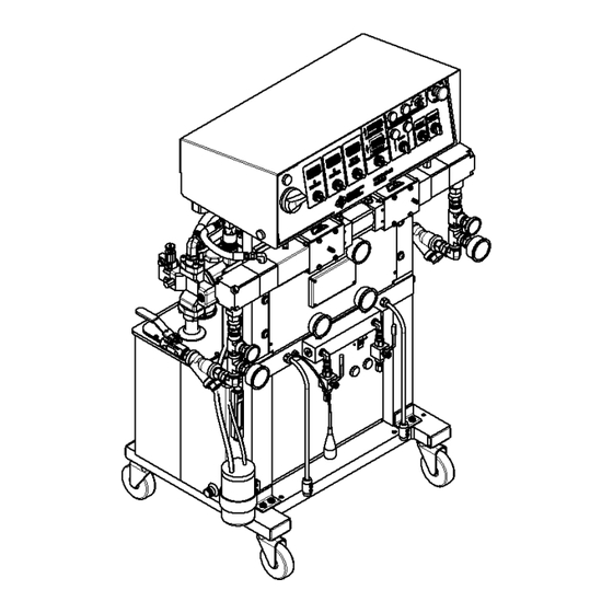
POLYURETHANE PHX-2 SERVICE MANUAL MACHINERY CORPORATION 5. DESCRIPTION 5 DESCRIPTION Figure 4: Component Identification - Front REVISION 1.6... - Page 15 POLYURETHANE PHX-2 SERVICE MANUAL MACHINERY CORPORATION 5. DESCRIPTION Figure 5: Component Identification - Back REVISION 1.6...
- Page 16 POLYURETHANE PHX-2 SERVICE MANUAL MACHINERY CORPORATION 5. DESCRIPTION A. Control Panel Controls and regulates the operation of the PH Series Proportioner. B. Isocyanate (Iso, A) Metering Pump Meters the Isocyanate material. C. Polyol (Poly, R) Metering Pump Meters the Polyol material.
- Page 17 POLYURETHANE PHX-2 SERVICE MANUAL MACHINERY CORPORATION 5. DESCRIPTION Figure 7: Front Panel Description N. Main Power Turns ON and OFF main power to the control panel. It must be turned ON for any operation to be performed with the unit. When turned ON, the red pilot will light.
- Page 18 POLYURETHANE PHX-2 SERVICE MANUAL MACHINERY CORPORATION 5. DESCRIPTION U. Totalizer Indicates the number of pump cycles to calculate material usage for both A and R side combined: Model Pressure Pump Size Cycles per Gal (3.79L) PHX-2 3,000PSI V. Auto Shut Down Switch Turns ON and OFF power to the Auto Shut Down unit.
-
Page 19: Installation
POLYURETHANE PHX-2 SERVICE MANUAL MACHINERY CORPORATION 6. INSTALLATION 6 INSTALLATION WARNING! Use suitable protection and follow the recommendations in the Safety Information enclosed and provided by material suppliers when installing or working with the Proportioner. CAUTION! Make sure the power cable is disconnected from the main power source before connecting to the Terminal Strip in the Console. - Page 20 Ensure Main Power Switch is OFF and incoming power is locked OFF before reversing power leads. Recheck rotation before proceeding with Installation. 5. Fill the Lube Reservoir with PMC Pump Lube or suitable dilutants. It is not necessary to prime the system. REVISION 1.6...
-
Page 21: Heated Hose Installation
POLYURETHANE PHX-2 SERVICE MANUAL MACHINERY CORPORATION 6. INSTALLATION HEATED HOSE INSTALLATION CAUTION! The material delivery Heated Hoses are color coded Red and Blue, allowing the user to recognize them. The Red corresponds to the Isocyanate (Iso, A) and the Blue to the Polyol (Poly, R). To avoid connection errors, the Coupling Connections of the Iso (A) and Poly (R) Heated Hoses are different sizes to ensure correct orientation. - Page 22 POLYURETHANE PHX-2 SERVICE MANUAL MACHINERY CORPORATION 6. INSTALLATION CAUTION! Ensure the proper mechanical and electrical connections of the Heated Hoses are made to avoid possible material leakage and Hose heat problems. 6. It is recommended the TSU (Temperature Sensing Unit) be installed between the last section of Heated Hose and the Gun Whip.
-
Page 23: Hose Heat Transformer
POLYURETHANE PHX-2 SERVICE MANUAL MACHINERY CORPORATION 6. INSTALLATION HOSE HEAT TRANSFORMER The Hose Heat Transformer offers the ability of connecting to different output voltages depending on the total length of the Heated Hose in use, maximizing the heating ability of the Heated Hose. The factory setting is 18 volts for use with 60 feet of Heated Hose. - Page 24 POLYURETHANE PHX-2 SERVICE MANUAL MACHINERY CORPORATION 6. INSTALLATION 7. Ensure the Manual Valves are CLOSED and connect the Coupling Block to the Heated Gun Whip. CAUTION! Excessive force closing or opening the Manual Valves may result in damage to the Manual Valves and/or Coupling Block.
-
Page 25: Proportioner Purging
POLYURETHANE PHX-2 SERVICE MANUAL MACHINERY CORPORATION 7. PROPORTIONER PURGING 7 PROPORTIONER PURGING WARNING! Use suitable Personal Protection Equipment (PPE) and follow the recommendations in the Safety Information provided by product suppliers when installing or working with the unit. WARNING! Do not turn the Temperature Controllers ON until the Proportioner purging procedure is complete and the Primary Heaters and Heated Hoses are filled with material. - Page 26 POLYURETHANE PHX-2 SERVICE MANUAL MACHINERY CORPORATION 7. PROPORTIONER PURGING 1. Turn Hydraulic Pressure Control (See Figure 5 on page 13) fully COUNTERCLOCKWISE. 2. Turn ON Main Power (See Figure 6 on page 15). Green pilot will light. 3. Turn ON Control Power (See Figure 6 on page 15). Switch will light.
-
Page 27: Pressure Balance Control
POLYURETHANE PHX-2 SERVICE MANUAL MACHINERY CORPORATION 8. PRESSURE BALANCE CONTROL 8 PRESSURE BALANCE CONTROL The PH Series Proportioner has been designed with a pressure balance control system. This system will give the operator of this machine the ability to control a pressure imbalance within certain predetermined parameters. -
Page 28: Digital Temperature Controller
POLYURETHANE PHX-2 SERVICE MANUAL MACHINERY CORPORATION 9. DIGITAL TEMPERATURE CONTROLLER 9 DIGITAL TEMPERATURE CONTROLLER The PH Series has three Digital Temperature Controllers to manage the temperatures for the Primary Heaters (Iso (A), Poly (R)) and the Heated Hose. The Hose Heater Controller is programmed different from the Iso (A) and Poly (R) Controllers and therefore not interchangeable with them. - Page 29 WARNING! The Controllers are factory programmed and are not field re-programmable. If a problem is encountered, contact your PMC Distributor. Do not attempt to change any of the programmed parameters. Do not substitute a Controller from an alternate supplier as its use may result in equipment damage and/or bodily injury.
-
Page 30: Start-Up
POLYURETHANE PHX-2 SERVICE MANUAL MACHINERY CORPORATION 10. START-UP 10 START-UP NOTE! Follow the recommended procedure in the order shown. CAUTION! The Start-up procedures assume that all steps in Proportioner purging have been performed and no problems were found. 1. Check the hydraulic fluid level and service as required. - Page 31 POLYURETHANE PHX-2 SERVICE MANUAL MACHINERY CORPORATION 10. START-UP NOTE! Directional Indicator Lights must indicate Metering Pump direction when Pump Switch is in the NORMAL position. If not, refer to Trouble Shooting section. 11a. Using the Hydraulic Pressure Control, adjust to the required stall pressure and check each Material Pressure Gauge.
- Page 32 POLYURETHANE PHX-2 SERVICE MANUAL MACHINERY CORPORATION 10. START-UP NOTE! Directional Indicator Lights must indicate Metering Pump direction when Pump Switch is in the NORMAL position. If not, refer to Trouble Shooting section. 11b. (See Figure 6 on page 15) - If this function is not needed, leave it in the off position.
-
Page 33: Shut Down
POLYURETHANE PHX-2 SERVICE MANUAL MACHINERY CORPORATION 11. SHUT DOWN 11 SHUT DOWN 11.1 SHORT-TERM Follow the procedure below for temporary shutdowns, such as lunch breaks: 1. Set Pump Switch (See Figure 6 on page 15) to the OFF position. 2. Turn both “A” and “R” Heaters OFF. Hose Heater should remain ON. Never leave Proportioner ON if unattended. -
Page 34: Troubleshooting
This chapter contains information on possible faults that may interrupt the operation of the PH Series Proportioner. The information provided will serve as a guideline to detect and resolve problems. In any case, feel free to contact your authorized PMC distributor, where a qualified technician will advise you. -
Page 35: Heaters
POLYURETHANE PHX-2 SERVICE MANUAL MACHINERY CORPORATION 12. TROUBLESHOOTING 12.1 HEATERS WARNING! Only qualified personnel should perform troubleshooting; unqualified personnel may cause damage to the unit, personnel, or property and put the operator at risk. The Heaters are components that reach high temperatures; you must wait until they cool before handling. - Page 36 POLYURETHANE PHX-2 SERVICE MANUAL MACHINERY CORPORATION 12. TROUBLESHOOTING • Problem: Primary heater does not heat and the display on the controller shows ambient temperature. Solutions: 1. Check that the light on the on/off switch is lit when the heater is turned on, if not replace the switch.
- Page 37 POLYURETHANE PHX-2 SERVICE MANUAL MACHINERY CORPORATION 12. TROUBLESHOOTING • Problem: Primary heater does not heat and the display on the controller shows an error message (SbEr, EEPE, CjEr, AdEr). Solutions: 1. Check position 6 and 7 on the heater controller for loose wires.
-
Page 38: Hydraulic Drive System
POLYURETHANE PHX-2 SERVICE MANUAL MACHINERY CORPORATION 12. TROUBLESHOOTING 12.2 HYDRAULIC DRIVE SYSTEM Frequent Hydraulic Drive System Problems Hydraulic Pump does not develop pressure and the electric motor is not Page 36 running. Hydraulic Pump does not develop pressure. Page 37 Low or zero hydraulic pressure with unusual Hydraulic Pump noises. - Page 39 POLYURETHANE PHX-2 SERVICE MANUAL MACHINERY CORPORATION 12. TROUBLESHOOTING • Problem: Hydraulic Pump does not develop pressure. Solutions: NOTE! Hydraulic pressure is not generated if the Motor Power Switch (See Figure 6 on page 15) is OFF or the Pump Switch (See Figure 6 on page 15) is in the OFF position.
-
Page 40: Metering Pump-Line
POLYURETHANE PHX-2 SERVICE MANUAL MACHINERY CORPORATION 12. TROUBLESHOOTING 12.3 METERING PUMP-LINE Figure 16: Metering Pump-Line Frequent Pump-Line Problems Metering pumps do not change direction and the pressures on both of Page 38 chemical gauges are lower than normal. Cavitation. Page 41 Pressure Loss: Discharge/Inlet Ball. - Page 41 POLYURETHANE PHX-2 SERVICE MANUAL MACHINERY CORPORATION 12. TROUBLESHOOTING NOTE! IF THE DIRECTIONAL INDICATOR LIGHT (Q, Page 15) IS ON CHECK THE REVERSING VALVE COIL ON THE SIDE THAT THE LIGHT IS ON. IF YOU HAVE 24 VOLTS DC AT THE PLUG, CHECK THE OHM’S RESISTANCE OF THE COIL, IT SHOULD READ APPROXIMATELY 19 OHM’s, IF NOT REPLACE THE COIL OR REVERSING VALVE.
- Page 42 POLYURETHANE PHX-2 SERVICE MANUAL MACHINERY CORPORATION 12. TROUBLESHOOTING 3. Safety Pressure Switch - Each Metering Pump has a Safety Pressure Switch set to 2,200 psi. for # 123 pumps, 3,200 psi for #61 pumps. When the material system reaches this pressure, the Safety Pressure Switch will remove power from the Directional Valve and Direction Indicator Lights (Q, section 5).
- Page 43 POLYURETHANE PHX-2 SERVICE MANUAL MACHINERY CORPORATION 12. TROUBLESHOOTING • Problem: Cavitation. Solutions: 1. Cavitations occur when the Metering Pump (B or C, section 5) requires a larger volume of material than the supply system (Transfer Pump) can furnish. This creates a “void” of material in the Metering Pump.
-
Page 44: Hose Heating
POLYURETHANE PHX-2 SERVICE MANUAL MACHINERY CORPORATION 12. TROUBLESHOOTING 12.4 HOSE HEATING WARNING! Before correcting any kind of defect, make sure the Main Power Switch is OFF and incoming power is locked OFF. NEVER access the inside of the Control Panel with the Proportioner power supply ON. The Heated Hose are components which reach high temperatures;... - Page 45 POLYURETHANE PHX-2 SERVICE MANUAL MACHINERY CORPORATION 12. TROUBLESHOOTING 5. To check the secondary side of the transformer, you must take an AC volt reading across the two leads coming out of the transformer that are connected to the “A” and “R” hose leads. If you are reading voltage (your volt reading will vary depending on what tap setting is used), most likely the problem is in the heated hose.
- Page 46 POLYURETHANE PHX-2 SERVICE MANUAL MACHINERY CORPORATION 12. TROUBLESHOOTING • Problem: Heated hose controller shows excessive temperature. Solutions: 1. Set the controller set point at least 20 degrees lower than the temperature shown on the controller. Briefly turn on the hose and look for the LED light on the solid-state relay to be on.
-
Page 47: Pressure Balance Control
If OFF, the Control Unit is not getting power. Check for loose or poor wire connections. If the Power/Run light still does not turn on, contact your authorized PMC distributor. b. If SOLID, the Control Unit has power but no program. Contact your authorized PMC distributor. -
Page 48: Maintenance
CAUTION! All repairs performed by unqualified personnel or the use of parts other than supplied by PMC may cause damage to the unit and put the operator at risk. REVISION 1.6... -
Page 49: Inlet Material Screens
POLYURETHANE PHX-2 SERVICE MANUAL MACHINERY CORPORATION 13. MAINTENANCE 13.1 INLET MATERIAL SCREENS Inspection of the Inlet Material Screens on a daily basis is no longer necessary as long as the following conditions are met. 1. Material drums are stored within the recommended material storage temperature range and drums are not opened prior to installing the Proportioner Material Transfer Pumps. -
Page 50: Iso Lubrication System
13.2 ISO LUBRICATION SYSTEM DAILY: Check the condition of the PMC Lube Oil in the Iso Lube Reservoir. Replace the PMC Lube Oil if you see significant changes in the color or signs of solidification. Ensure inside of Reservoir is wiped clean. -
Page 51: Hydraulic Drive System
POLYURETHANE PHX-2 SERVICE MANUAL MACHINERY CORPORATION 13. MAINTENANCE 13.3 HYDRAULIC DRIVE SYSTEM WARNING! Before performing any maintenance, make sure the Main Power Switch is OFF and incoming power is locked OFF. The Hydraulic Unit is a component that works under pressure. Do not open any connection or carry out maintenance on components subject to pressure until all pressure has been bled to zero. -
Page 52: Metering Pump-Line
POLYURETHANE PHX-2 SERVICE MANUAL MACHINERY CORPORATION 13. MAINTENANCE 13.4 METERING PUMP-LINE WARNING! Before performing any maintenance, make sure the Main Power Switch is OFF and incoming power is locked OFF. Allow material temperature to cool below 80 F and bleed all material pressure to zero. -
Page 53: Material Heater
POLYURETHANE PHX-2 SERVICE MANUAL MACHINERY CORPORATION 13. MAINTENANCE 13.6 MATERIAL HEATER WARNING! Before performing any maintenance, make sure the Main Power Switch is OFF and incoming power is locked OFF. NEVER access the inside of the Control Panel with the Proportioner power supply ON. The Heaters are components that reach high temperatures;... - Page 54 POLYURETHANE PHX-2 SERVICE MANUAL MACHINERY CORPORATION 13. MAINTENANCE WARNING! Before performing any maintenance, make sure the Main Power Switch is OFF and incoming power is locked OFF. NEVER access the inside of the Control Panel with the Proportioner power supply ON. The Heaters are components that reach high temperatures;...
-
Page 55: Hydraulic Oil Specifications
POLYURETHANE PHX-2 SERVICE MANUAL MACHINERY CORPORATION 14. HYDRAULIC OIL SPECIFICATIONS 14 HYDRAULIC OIL SPECIFICATIONS Recommended Hydraulic Oil Specification: ISO/ASTM Viscosity Grade 32 Viscosity: 28.8 – 35.2 SSU at 104 F Rust and Oxidation Inhibited ° 14.1 MANUFACTURERS • Mobil DTE24 (Recommended) •... -
Page 56: Parts Identification
POLYURETHANE PHX-2 SERVICE MANUAL MACHINERY CORPORATION 15. PARTS IDENTIFICATION 15 PARTS IDENTIFICATION 15.1 FRAME ASSEMBLY Figure 21: Frame Assembly (FR-10) REVISION 1.6... - Page 57 POLYURETHANE PHX-2 SERVICE MANUAL MACHINERY CORPORATION 15. PARTS IDENTIFICATION FRAME ASSEMBLY (FR-10) ITEM PART NUMBER DESCRIPTION 200950 GROMMET, 1.750” GD, 0.375” GW, 1.500” ID 200951 GROMMET, 1.000” GD, 0.125” GW, 0.813” ID 201060 WASHER, LOCK, 1/4, 18-8 SS 201328 GROMMET, 2.250” GD, 0.125” GW, 2.000” ID 201583 SHCS, 3/8-16 X 2.0, 18-8 SS...
-
Page 58: Prox Sensor Assembly
POLYURETHANE PHX-2 SERVICE MANUAL MACHINERY CORPORATION 15. PARTS IDENTIFICATION 15.2 PROX SENSOR ASSEMBLY Figure 22: Prox. Sensor Assembly (RM-243) PROX SENSOR ASSEMBLY (RM-243) ITEM PART NUMBER DESCRIPTION 201930 HHCS, 1/4-20 X 1.0, ZP GRD8 202401 WASHER, FLAT, 1/4, ZP SAE... -
Page 59: Hydraulic Manifold Assembly
POLYURETHANE PHX-2 SERVICE MANUAL MACHINERY CORPORATION 15. PARTS IDENTIFICATION 15.3 HYDRAULIC MANIFOLD ASSEMBLY Figure 23: Hydraulic Manifold Assembly (HI-05335) HYDRAULIC MANIFOLD ASSEMBLY (HI-05335) ITEM PART NUMBER DESCRIPTION HI-05006-6 1/4 NPT X 6 JIC GAUGE FITTING HI-05007 6 ORB X 6 JIC... -
Page 60: Exit Manifold Assembly
POLYURETHANE PHX-2 SERVICE MANUAL MACHINERY CORPORATION 15. PARTS IDENTIFICATION 15.4 EXIT MANIFOLD ASSEMBLY Figure 24: Exit Manifold Assembly (HI-05343) EXIT MANIFOLD ASSEMBLY (HI-05343) ITEM PART NUMBER DESCRIPTION HI-05011 6 ORB X 6 JIC NIPPLE HI-05028 PRESSURE GAUGE 0-3000 PSI (HI-05331) -
Page 61: Hydraulic Cylinder Assembly
POLYURETHANE PHX-2 SERVICE MANUAL MACHINERY CORPORATION 15. PARTS IDENTIFICATION 15.5 HYDRAULIC CYLINDER ASSEMBLY Figure 25: Hydraulic Cylinder Assembly (HI-05336) REVISION 1.6... -
Page 62: Hydraulic Cylinder Rebuild Kit
POLYURETHANE PHX-2 SERVICE MANUAL MACHINERY CORPORATION 15. PARTS IDENTIFICATION HYDRAULIC CYLINDER ASSEMBLY (HI-05336) ITEM PART NUMBER DESCRIPTION 201580 WASHER, FLAT, 5/16, 18-8 SS 201591 FHCS, #8-32 X 0375, 18-8 SS 202145 WASHER, LOCK, 5/16, 18-8 SS 202212 HHCS, 5/16-18 X 7.500, ZP GRD5... - Page 63 POLYURETHANE PHX-2 SERVICE MANUAL MACHINERY CORPORATION 15. PARTS IDENTIFICATION Figure 26: Hydraulic Seal Detail View Figure 27: Hydraulic Piston Detail View REVISION 1.6...
-
Page 64: A & R Single Pump Assembly
POLYURETHANE PHX-2 SERVICE MANUAL MACHINERY CORPORATION 15. PARTS IDENTIFICATION 15.6 A & R SINGLE PUMP ASSEMBLY Figure 28: A & R Single Pump Assembly (202587) REVISION 1.6... - Page 65 POLYURETHANE PHX-2 SERVICE MANUAL MACHINERY CORPORATION 15. PARTS IDENTIFICATION A & R SINGLE PUMP ASSEMBLY (202587) ITEM PART NUMBER DESCRIPTION 202574 INLET BODY, BTM FEED, HP 202761 INLET BODY, BOTTOM FEED 202763 RETAINING RING, INTERNAL, HP 202764 PISTON VALVE, HP...
-
Page 66: Pump-Line Seal Orientation
POLYURETHANE PHX-2 SERVICE MANUAL MACHINERY CORPORATION 15. PARTS IDENTIFICATION 15.7 PUMP-LINE SEAL ORIENTATION Figure 30: A & R Single Pump Assembly Detail A Figure 31: A & R Single Pump Assembly Detail B REVISION 1.6... -
Page 67: Pump-Line Assembly
POLYURETHANE PHX-2 SERVICE MANUAL MACHINERY CORPORATION 15. PARTS IDENTIFICATION 15.8 PUMP-LINE ASSEMBLY Figure 32: Pump-Line Assembly (202588) REVISION 1.6... -
Page 68: Pump Rebuild Kit
POLYURETHANE PHX-2 SERVICE MANUAL MACHINERY CORPORATION 15. PARTS IDENTIFICATION PUMP LINE ASSEMBLY - HIGH PRESSURE (202588) ITEM PART NUMBER DESCRIPTION 202242 LUBE SECTION, ROD SEAL, HP 202243 SEAL, ROD 1.00 DIA 202587 30:1 A/R BOTTOM FEED PUMP 202777 SHCS, 3/8-16 X 3.000, ZP ALLOY 202778 SHCS, 1/4-20 X 1.000, ZP ALLOY... -
Page 69: Inlet Monitoring Assembly
POLYURETHANE PHX-2 SERVICE MANUAL MACHINERY CORPORATION 15. PARTS IDENTIFICATION 15.9 INLET MONITORING ASSEMBLY Figure 33: Inlet Monitoring Assembly (KT-05005) INLET MONITORING ASSEMBLY (KT-05005) ITEM PART NUMBER DESCRIPTION HI-05015 3/4 FTG, 90 DEG ELBOW, 3/4 MNPTF, STL HI-05017 FTG, UNION, 3/4 MNPTF, STL... -
Page 70: Y-Strainer Assembly "A" Side
POLYURETHANE PHX-2 SERVICE MANUAL MACHINERY CORPORATION 15. PARTS IDENTIFICATION 15.10 Y-STRAINER ASSEMBLY “A” SIDE Figure 34: Y-Strainer Assembly "A" Side (YS-1) Y-STRAINER ASSEMBLY “A” SIDE (YS-1) ITEM PART NUMBER DESCRIPTION HI-05016 3/4 NPTM X 3/4 NPTF SW HI-05017 3/4 MNPT UNION... -
Page 71: Y-Strainer Assembly "R" Side
POLYURETHANE PHX-2 SERVICE MANUAL MACHINERY CORPORATION 15. PARTS IDENTIFICATION 15.11 Y-STRAINER ASSEMBLY “R” SIDE Figure 35: Y-Strainer Assembly "R" Side (YS-2) Y-Strainer Assembly “R” Side (YS-2) ITEM PART NUMBER DESCRIPTION HI-05016 3/4 NPTM X 3/4 NPTF SW HI-05017 3/4 MNPT UNION... -
Page 72: Heater Assembly
POLYURETHANE PHX-2 SERVICE MANUAL MACHINERY CORPORATION 15. PARTS IDENTIFICATION 15.12 HEATER ASSEMBLY Figure 36: Heater Assembly, 6 Rod - A Figure 37: Heater Assembly, 6 Rod - B REVISION 1.6... - Page 73 POLYURETHANE PHX-2 SERVICE MANUAL MACHINERY CORPORATION 15. PARTS IDENTIFICATION PREHEATER ASSEMBLY, 6-ROD PH-21 (7.5kW) PH-22 (9kW) PH-23 (10.5kW) ITEM PART NUMBER DESCRIPTION 200939 FERRULE, 10 AWG, YELLOW 201559 BHCS, 1/4-20 X 1.500, 18-8 SS 201561 BHCS, #6-32 X 0.375, 18-8 SS 201899 BHCS, 1/4-20 X 0.750, 18-8 SS...
- Page 74 POLYURETHANE PHX-2 SERVICE MANUAL MACHINERY CORPORATION 15. PARTS IDENTIFICATION Figure 38: Heater Assembly, 8 Rod - A Figure 39: Heater Assembly, 8 Rod - B REVISION 1.6...
- Page 75 POLYURETHANE PHX-2 SERVICE MANUAL MACHINERY CORPORATION 15. PARTS IDENTIFICATION PREHEATER ASSEMBLY. 8-ROD PH-33 (14kW) ITEM PART NUMBER DESCRIPTION 200939 FERRULE, 10 AWG, YELLOW 201559 BHCS, 1/4-20 X 1.500, 18-8 SS 201561 BHCS, #6-32 X 0.375, 18-8 SS 201899 BHCS, 1/4-20 X 0.750, 18-8 SS...
-
Page 76: Motor-Line Assembly
POLYURETHANE PHX-2 SERVICE MANUAL MACHINERY CORPORATION 15. PARTS IDENTIFICATION 15.13 MOTOR-LINE ASSEMBLY Figure 40: Motor-Line Assembly REVISION 1.6... - Page 77 POLYURETHANE PHX-2 SERVICE MANUAL MACHINERY CORPORATION 15. PARTS IDENTIFICATION Figure 41: Motor Comparison MOTOR-LINE ASSEMBLY (ML-3)/(ML-4) ITEM PART NUMBER DESCRIPTION 202152 HHCS, 3/8-16 X 1.000, ZP GRD8 202194 WASHER, FLAT, 1/2, ZP SAE 202195 WASHER, LOCK, 1/2, ZP 202207 HHCS, 1/2-13 X 1.25, ZP GRD8...
-
Page 78: Final Assembly
POLYURETHANE PHX-2 SERVICE MANUAL MACHINERY CORPORATION 15. PARTS IDENTIFICATION 15.14 FINAL ASSEMBLY Figure 42: PHX-2 Final Assembly - A REVISION 1.6... - Page 79 POLYURETHANE PHX-2 SERVICE MANUAL MACHINERY CORPORATION 15. PARTS IDENTIFICATION Figure 43: PHX-2 Final Assembly – B REVISION 1.6...
- Page 80 POLYURETHANE PHX-2 SERVICE MANUAL MACHINERY CORPORATION 15. PARTS IDENTIFICATION Figure 44: PHX-2 Final Assembly - C REVISION 1.6...
- Page 81 POLYURETHANE PHX-2 SERVICE MANUAL MACHINERY CORPORATION 15. PARTS IDENTIFICATION Figure 45: PHX-2 Final Assembly - D REVISION 1.6...
- Page 82 202292 BHCS, PATCH, #8-32 X 0.250, BO 202401 WASHER, FLAT, 1/4, ZP SAE 202456 BLEED VALVE KIT, PH(X_-2 202588 PUMPLINE, HP BTM FEED, PHX-2 202553 WASHER, LOCK, 1/4, ZP 202554 WASHER, LOCK, 5/16, ZP 202555 WASHER, LOCK, 3/8, ZP 202556...
- Page 83 POLYURETHANE PHX-2 SERVICE MANUAL MACHINERY CORPORATION 15. PARTS IDENTIFICATION ITEM PART NUMBER DESCRIPTION EL-63 PREHEATER ELECTRICAL CONNECTOR EL-00118A-00-1 HOSE BREAKER MOUNTING PLATE EL-150 CIRCUIT BREAKER 63AMP EL-192 TERMINAL BLOCK EL-193 INRUSH CURRENT LIMITER EL-195 0-5000 PRESS TRANSDUCER EL-05220-01 CONSOLE KNOBS...
- Page 84 POLYURETHANE PHX-2 SERVICE MANUAL MACHINERY CORPORATION 15. PARTS IDENTIFICATION ITEM PART NUMBER DESCRIPTION RM-05201-2 CONSOLE ENCLOSURE, TOP RM-E-64-0100 POLYFLO TUBING, 3/8’’ RM-E-86-0100 POLYFLO TUBING, 1/2’’ RM-RL-05230-01 3/4 X 1/4 X 100’ FLEX CONDUIT TL-01 TOOL, CLEVIS EXTRACTOR TN-04196 HOSE CLAMP YS-1 Y-STRAINER ASSY “A”...
-
Page 85: Phx-2 Hoses
POLYURETHANE PHX-2 SERVICE MANUAL MACHINERY CORPORATION 15. PARTS IDENTIFICATION 15.15 PHX-2 HOSES Figure 46: Proportioner Hoses - Front Figure 47: Proportioner Hoses - Back REVISION 1.6... -
Page 86: Half Inch Hose Kit
POLYURETHANE PHX-2 SERVICE MANUAL MACHINERY CORPORATION 15. PARTS IDENTIFICATION PROPORTIONER HOSES ITEM PART NUMBER DESCRIPTION HI-05047-2 9” HOSE, HYD PUMP TO TANK HI-05047-6 13” HOSE ASSY, 90 DEG HI-05047-7 HOSE ASSY, HYD PUMP TO TANK HI-05047-8 HOSE ASSY HI-05013 1/2 X 2 HOSE, HYD TANK RETURN HI-05047-4 13”... -
Page 87: Lube Bottle Components
POLYURETHANE PHX-2 SERVICE MANUAL MACHINERY CORPORATION 15. PARTS IDENTIFICATION 15.16 LUBE BOTTLE COMPONENTS Figure 48: Lube Bottle Components LUBE BOTTLE COMPONENTS ITEM PART NUMBER DESCRIPTION GP-00960-1-GAL PUMP LUBE GALLON GP-00960-1-QRT PUMP LUBE QUART MA-00024A-1 1/2” X 43’ PLASTIC TUBING, RETURN MA-00025A-1 3/8”... -
Page 88: Bleed Valve Kit
POLYURETHANE PHX-2 SERVICE MANUAL MACHINERY CORPORATION 15. PARTS IDENTIFICATION 15.17 BLEED VALVE KIT Figure 49: Bleed Valve Kit (202456) BLEED VALVE KIT (202456) ITEM PART NUMBER DESCRIPTION 200226 5 JIC CAP 200227 6 JIC CAP 202430 BALL VALVE, 1/4 NPT, 5000 PSI...
Need help?
Do you have a question about the PHX-2 and is the answer not in the manual?
Questions and answers