Table of Contents
Advertisement
Before installing the PH Series Proportioner and start-up, carefully
read all the technical and safety documentation included in this
manual. Pay special attention to the information in order to know and
understand the operation and the conditions of use of the PH Series
Proportioner. All of the information is aimed at improving user safety
and avoiding possible breakdowns from the incorrect use of the PH
Series Proportioner.
Classic
PH/PHX-25
PH/PHX-40
Proportioners
Hydraulic, Heated, Plural Component
Proportioner
For spraying Polyurethane Foam and
Coatings
For Professional Use Only
Not approved for use in explosive
atmosphere locations
Service Manual
Ref. # MN-04014
Revision 3.3
September 23, 2016
Polyurethane Machinery Corp.
Corporate: 1 Komo Dr, Lakewood, NJ 08701
Manufacturing: 2 Komo Dr, Lakewood, NJ 08701
Phone: 732-415-4400
Fax: 732-364-4025
URL:
http://www.polymac-usa.com
Advertisement
Table of Contents

Related Manuals for PMC PH-25


Summary of Contents for PMC PH-25
- Page 1 Classic PH/PHX-25 PH/PHX-40 Proportioners Hydraulic, Heated, Plural Component Proportioner For spraying Polyurethane Foam and Coatings For Professional Use Only Not approved for use in explosive atmosphere locations Service Manual Ref. # MN-04014 Revision 3.3 September 23, 2016 Polyurethane Machinery Corp. Corporate: 1 Komo Dr, Lakewood, NJ 08701 Manufacturing: 2 Komo Dr, Lakewood, NJ 08701 Phone: 732-415-4400...
-
Page 2: Table Of Contents
TABLE OF CONTENTS WARRANTY ..........................1 SAFETY AND HANDLING ...................... 3 CHARACTERISTICS ......................5 PRINCIPAL HEATING SYSTEM ..................5 HOSE HEATING SYSTEM ....................5 DOUBLE ACTING OPPOSED PISTON METERING PUMPS ..........5 PRESSURE BALANCE CONTROL SYSTEM ..............6 PH(X)-25 TECHNICAL SPECIFICATIONS ................7 ELECTRICAL ........................ - Page 3 TABLE OF CONTENTS PRESSURE BALANCE CONTROL ................... 41 MAINTENANCE ........................42 INLET MATERIAL SCREENS .................... 43 ISO LUBRICATION SYSTEM .................... 44 HYDRAULIC DRIVE SYSTEM ................... 45 METERING PUMP LINE ....................46 Pump Base Service ........................46 Pump Seal Replacement ......................47 METERING PUMP REMOVAL ....................
- Page 4 TABLE OF CONTENTS PH-SERIES PROPORTIONER ..................84 LUBE BOTTLE COMPONENTS ..................87 HOSES ..........................88 BLEED SYSTEM ....................... 89...
-
Page 5: Warranty
Defective in material or workmanship, it is Customer’s responsibility to contact PMC and return the Product to PMC as directed by PMC, freight prepaid. If PMC determines that the Product is Defective and that such Defect is covered by this Warranty, PMC will credit Customer for the reasonable freight charges incurred by Customer in returning the Defective Product to PMC, and PMC (or its authorized agent) will, at PMC’s option, repair or replace the Product, subject to... - Page 6 No Rights Implied: Nothing in the sale, lease or rental of any Product by PMC shall be construed to grant any right, interest or license in or under any patent, trademark, copyright, trade secret or other proprietary right or material owned by anyone;...
-
Page 7: Safety And Handling
Keep this Operations Manual for future consultation of useful information at all times. If you lose this manual, ask for a new copy from your PMC Distributor or go online and visit our web site at www.polymac-usa.com. - Page 8 Always use liquids and solvents that are compatible with the unit. If in doubt, consult your PMC Distributor. When working with the PH Series Proportioner, it is recommended that the operator wear suitable clothing and elements of personal protection, including, without limitation, gloves, protective goggles, safety footwear, and face masks.
-
Page 9: Characteristics
CHARACTERISTICS Classic PH Series Proportioner has been designed and built for the application of polyurea chemical systems, polyurethane foam chemical systems, and some specific two- component epoxy systems. PRINCIPAL HEATING SYSTEM The Proportioners consist of two (2) independent Material Heaters without internal seals. Each heater for the PH(X)-25 Proportioner has four (4) Heating Elements rated at 1,000, 1,250 or 1,500 watts, each giving the Proportioner a total heat of 8,000, 10,000, or 12,000 watts. -
Page 10: Pressure Balance Control System
CHARACTERISTICS PRESSURE BALANCE CONTROL SYSTEM The Pressure Balance Control (PBC) system provides better control over a chemical pressure imbalance. When the system is turned off, the Proportioner will perform as if there is no PBC system and will continue pumping material. When the system is turned on, it will continually monitor the pressure between the two chemicals (known as the pressure differential). -
Page 11: Ph(X)-25 Technical Specifications
PH(X)-25 TECHNICAL SPECIFICATIONS ELECTRICAL Main Voltage: ______________________________________ 3 x 208-230V, 50/60Hz Electrical Consumption: (2 x 4 kW Heaters) _____________________ 40 A @ 3 x 230V Electrical Consumption: (2 x 5 kW Heaters) _____________________ 49 A @ 3 x 230V Electrical Consumption: (2 x 6 kW Heaters) _____________________ 57 A @ 3 x 230V Main Voltage: _________________________________________ 1 x 208-230V, 60Hz Electrical Consumption: (2 x 4 kW Heaters) _____________________ 61 A @ 1 x 230V Electrical Consumption: (2 x 5 kW Heaters) _____________________ 70 A @ 1 x 230V... -
Page 12: Ph(X)-40 Technical Specifications
PH(X)-40 TECHNICAL SPECIFICATIONS ELECTRICAL Main Voltage: ______________________________________ 3 x 208-230V, 50/60Hz Electrical Consumption: (2 x 7.5 kW Heaters) ___________________ 75 A @ 3 x 230V Electrical Consumption: (2 x 9.0 kW Heaters) ___________________ 89 A @ 3 x 230V Electrical Consumption: (2 x 10.5 kW Heaters) _________________ 103 A @ 3 x 230V Main Voltage: _________________________________________ 1 x 208-230V, 60Hz Electrical Consumption: (2 x 7.5 kW Heaters) __________________ 130 A @ 1 x 230V Material Heater Power: (2 x 7.5 kW) ___________________________________ 15 kW... -
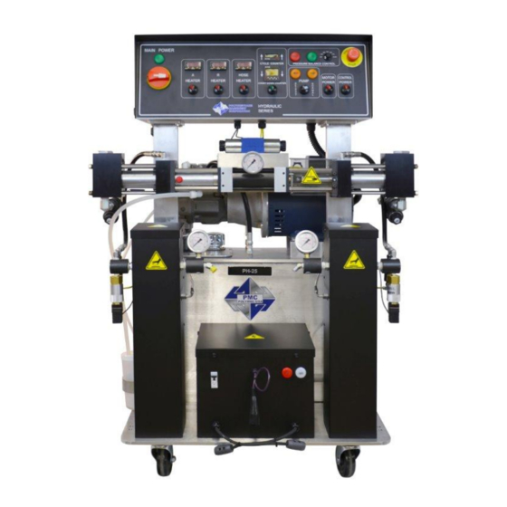
Page 13: Description
DESCRIPTION CLASSIC PH-SERIES PROPORTIONER... - Page 14 DESCRIPTION Control Panel Controls and regulates the operation of the PH Series Proportioner. Isocyanate (Iso, A) Metering Pump Meters the Isocyanate material. Polyol (Poly, R) Metering Pump Meters the Polyol material. Isocyanate (Iso, A) Heater Heats the incoming Isocyanate to a temperature set by the operator. Polyol (Poly, R) Heater Heats the incoming Polyol to a temperature set by the operator.
- Page 15 DESCRIPTION CLASSIS PH-SERIES CONTROL PANEL Main Power - Turns ON and OFF main power to the control panel. It must be turned ON for any operation to be performed with the unit. When turned ON, the green pilot light will be lit. Emergency Stop - Interrupts the PH Series control power circuit to stop all motion and heating.
- Page 16 DESCRIPTION W. Motor Switch - Turns ON and OFF the Electric/Hydraulic Motor. When turned ON the switch will be lit. In the event of an overload of the Motor, pilot light will turn OFF and Motor will stop. Pump Switch Off - Removes power from the pump circuit.
-
Page 17: Installation
INSTALLATION WARNING! suitable protection follow recommendations in the Safety Information enclosed and provided by material suppliers when installing or working with the Proportioner. CAUTION! Inside the console is a Terminal Strip for connecting the main power (wire not supplied) to the PH Series Proportioner. - Page 18 Installation. CAUTION! Ensure Main Power Switch is OFF and incoming power is locked OFF before reversing power leads. 5. Fill the Lube Reservoir with PMC Pump Lube or suitable diluents. It is not necessary to prime the system.
-
Page 19: Heated Hose Installation
INSTALLATION HEATED HOSE INSTALLATION CAUTION! The material delivery Heated Hoses are color coded Red and Blue allowing the user to recognize them. The Red corresponds to the Isocyanate (Iso, A) and the Blue to the Polyol (Poly, R). To avoid connection errors the Coupling Connections of the Iso (A) and Poly (R) Heated Hoses are also different sizes, which makes it difficult to swap connections. - Page 20 INSTALLATION 5. Repeat the above steps to connect the “Fast-Lock” Connectors that you will find on all Heated Hose power wire. CAUTION! Ensure the proper mechanical and electrical connections of the Heated Hoses are made to avoid possible material leakage and Hose heat problems.
-
Page 21: Transformer Settings
INSTALLATION TRANSFORMER SETTINGS The Hose Heat Transformer offers the ability of RECOMMENDED TAP connecting to different output voltages depending SETTINGS on the total length of the Heated Hose in use, maximizing the heating ability of the Heated Hose. Feet Meters The factory setting is 18 volts for use with 60 feet 120V 125.0... - Page 22 INSTALLATION 7. Ensure the Manual Valves are CLOSED and connect the Coupling Block to the Heated Gun Whip. CAUTION! Excessive force closing or opening the Manual Valves may result in damage to the Manual Valves and/or Coupling Block. 8. Connect the Transfer Pump/Heated Hose Assemblies air supply and air dryer systems as required.
-
Page 23: Proportioner Purging
PROPORTIONER PURGING WARNING! Use suitable Personal Protection Equipment (PPE) and follow the recommendations in the Safety Information provided by product suppliers when installing or working with the unit. NOTE! Before using the Proportioner it is necessary to purge the entire system, including Heated Hoses of mineral oil and air left over from Quality Control testing. - Page 24 PROPORTIONER PURGING 10. Set Pump Switch (X, page 11) to NORMAL. Turn Hydraulic Pressure Control CLOCKWISE (N, page 10) increasing material pressure to 400 psi (27 bar). Both Material Pressure Gauges (H, K, page 10) should read the same. 11. Check all connections for leaks. 12.
-
Page 25: Pressure Balance Control
PRESSURE BALANCE CONTROL The PH Series Proportioner has been designed with a pressure balance control system. This system will give the operator of this machine the ability to control a pressure imbalance within certain predetermined parameters. The system consists of: Selector Switch Fault Light On Light... -
Page 26: Digital Temperature Controller
The Controllers are factory programmed and are not field re-programmable. If a problem is encountered, contact your PMC Distributor. Do not attempt to change any of the programmed parameters. Do not substitute a Controller from an alternate supplier as its use may result in equipment damage and/or bodily injury. -
Page 27: Start-Up
Proportioner purging have been performed and no problems found. 1. Check the condition of the PMC pump lube in the Iso (A) Lube Reservoir (page 14). Replace the PMC pump lube if you see significant changes in the color or signs of solidification. - Page 28 START-UP NOTE! Directional Indicator Lights must indicate Metering Pump direction when Pump Switch is in the NORMAL position. If not, refer to Trouble Shooting section. 11. Using the Hydraulic Pressure Control, adjust to the required stall pressure and check each Material Pressure Gauge. 12.
-
Page 29: Shut-Down
SHUT-DOWN Short Term Follow the procedure below for temporary shut-downs, such as lunch breaks: 1. Set Pump Switch (X, page 11) to OFF position. 2. Turn each Heater OFF. Hose Heater should remain ON. Never leave Proportioner ON if unattended. 3. -
Page 30: Troubleshooting
This chapter contains information on possible faults that may interrupt the operation of the PH Series Proportioner. The information provided will serve as a guideline to detect and resolve problems. In any case, feel free to contact your authorized PMC Distributor, where a qualified technician will advise you. -
Page 31: Heaters
TROUBLESHOOTING HEATERS WARNING! Before troubleshooting make sure the Main Power Switch is OFF and incoming power is locked OFF. NEVER access the inside of the Control Panel with the Proportioner power supply ON. The Heaters are components that reach high temperatures; you must wait until they cool before handling. - Page 32 TROUBLESHOOTING Follow the recommended procedure in the indicated order to solve the problem and avoid unnecessary repairs. Make sure all Switches are in the correct position and Indicator Lights ON before determining the existence of a fault. PROBLEM Primary heater does not heat and the display on the controller shows ambient temperature.
- Page 33 TROUBLESHOOTING across position 1 and 2 to make sure that the controller is powered up, your reading will be 208 to 230 volts AC. If no voltage is present check for loose wires or a malfunction of the heater circuit breaker. PROBLEM Primary heater does not heat and the display on the controller shows a flashing error message SbEr.
- Page 34 TROUBLESHOOTING 3. One or more of the fire rods in the heater have malfunctioned. Remove the heater cover and disconnect the wires to measure the resistance across each rod. Installing a smaller mixing chamber in the gun may allow you to spray until a new rod(s) is installed.
-
Page 35: Hydraulic Drive System
TROUBLESHOOTING HYDRAULIC DRIVE SYSTEM Follow the recommended procedure in the indicated order to solve the problem and avoid unnecessary repairs. Make sure all Switches are in the correct position and Indicator Lights ON before determining the existence of a fault. WARNING! Before correcting any kind of defect, make sure the Main Power Switch is OFF and the incoming power is... - Page 36 TROUBLESHOOTING PROBLEM: Motor runs but Hydraulic Pump does not develop pressure SOLUTIONS: NOTE! Hydraulic pressure is not generated if the Motor Power Switch (W, page 12) is OFF or the Pump Switch (X, page 11) is in the OFF position. With the Pump Switch in the NORMAL position, the failure of the Hydraulic Pump to develop pressure is loss of pump suction (prime).
-
Page 37: Metering Pump Line
TROUBLESHOOTING METERING PUMP LINE Follow the recommended procedures in the indicated order to solve the problem and avoid unnecessary repairs. Make sure all Switches are in the correct position and Indicator Lights ON before determining the existence of a fault. PROBLEM: Metering pumps do not change direction and the pressures on both of the chemical gauges are lower than normal. - Page 38 TROUBLESHOOTING NOTE! IF THE DIRECTIONAL LIGHT IS OFF PROCEED BELOW NOTE! BEFORE TROUBLESHOOTING, THE REVERSING SWITCH PLATE MUST BE MOVED AWAY FROM THE SWITCH. d. Bleed down the chemical pressures. e. Ensure Pump Switch (X, page 11) is OFF. Turn on the motor (W, page 12). g.
- Page 39 Safety Pressure Switch - Each Metering Pump has a Safety Pressure Switch (I, L, page 10). For PH-25 and PH-40 Proportioners, the Safety Pressure Switch is set to 2,200 PSI (152 bar). For PH(X)-25 Proportioners, the Safety Pressure Switch is set to 3,200 PSI (221 bar).
- Page 40 TROUBLESHOOTING Cavitation - Cavitation occurs when the Metering Pump (B, or C, page 10) requires a larger volume of material than the supply system (Transfer Pump) can furnish. This creates a "void" of material in the Metering Pump. The most common causes of cavitation are: a.
-
Page 41: Hose Heating
TROUBLESHOOTING HOSE HEATING WARNING! Before correcting any kind of defect, make sure the Main Power Switch is OFF and incoming power is locked OFF. NEVER access the inside of the Control Panel with the Proportioner power supply ON. The Heated Hoses are components which reach high temperatures. - Page 42 TROUBLESHOOTING 5. Look at the two lights located on the front of the transformer. If the voltage light is lit and the AMP light is off the problem could in the heated hoses. If the voltage light is on there is power to the primary side of the transformer. To check the secondary side of the transformer you must take an AC volt reading across the two leads coming out of the transformer that are connected to the “A”...
- Page 43 TROUBLESHOOTING PROBLEM: Hose does not heat and the display on the controller shows a flashing error message “SbEr.” SOLUTIONS: 1. Check position 9 and 10 on the heater controller for loose wires. If the wires are tight, move to the next step. 2.
- Page 44 Proportioner power supply ON. NOTE! In the event an equipment problem cannot be solved after following the detailed instructions contained in this manual, please contact your PMC authorized distributor and they have direct contact with PMC Technical Service Department. NOTE! For all parts and field service, contact your PMC authorized distributor.
-
Page 45: Pressure Balance Control
ON light turns off, and the FAULT light turns on), but the pumps do not shut off, check for continuity between contacts 11 and 12 on CR1. If there is continuity, contact your authorized PMC distributor. If there is discontinuity, proceed to the next step. -
Page 46: Maintenance
CAUTION! All repairs performed by unqualified personnel or the use of parts other than supplied by PMC may cause damage to the unit and put the operator at risk. -
Page 47: Inlet Material Screens
MAINTENANCE INLET MATERIAL SCREENS Inspection of the Inlet Material Screens on a daily basis is no longer necessary as long as the following conditions are met. 1. Material drums are stored within the recommended material storage temperature range and drums are not opened prior to installing the Proportioner Material Transfer Drum Pumps. -
Page 48: Iso Lubrication System
MAINTENANCE ISO LUBRICATION SYSTEM Daily: Check the condition of the PMC Lube Oil in the Iso Lube Reservoir. Replace the PMC Lube Oil if you see significant changes in the color or signs of solidification. Ensure inside of Reservoir is wiped clean. -
Page 49: Hydraulic Drive System
MAINTENANCE HYDRAULIC DRIVE SYSTEM WARNING! Before performing any maintenance, make sure the Main Power Switch is OFF and incoming power is locked OFF. The Hydraulic Unit is a component that works under pressure. Do not open any connection or carry out maintenance on components subject to pressure until all press has been bled to zero. -
Page 50: Metering Pump Line
MAINTENANCE METERING PUMP LINE Before performing any maintenance, WARNING! make sure the Main Power Switch is OFF and incoming power is locked OFF. Allow material temperature to cool below 80 F (27 C) and bleed all material pressure to zero. Weekly: When the Proportioning Pumps are functioning properly it is not unusual for a small amount of Poly (R) material to appear on the Pump Shaft. -
Page 51: Pump Seal Replacement
MAINTENANCE d. Using supplied Ball Seat Tool (TL-02), check for proper Ball Seat/Ball Seat Gasket compression. Snug Seat up to ¼ turn maximum 30 ft-lbs (41 N-m). Pump Seal Replacement NOTE! Refer to Parts Identification Drawing for reference. When the Iso (A) Proportioning Pump Cylinder is disassembled for service, all parts included in the Seal Kit (KT-05001-120 or KT-05001-080) should be replaced. -
Page 52: Material Heater
MAINTENANCE MATERIAL HEATER WARNING! Before performing any maintenance, make sure the Main Power Switch is OFF and incoming power is locked OFF. NEVER access the inside of the Control Panel with the Proportioner power supply ON. The Heaters are components that reach high temperatures; you must wait until they have cooled before handling and bleed all material pressure to zero. -
Page 53: Heating Rod
MAINTENANCE WARNING! Before performing any maintenance, make sure the Main Power Switch is OFF and incoming power is locked OFF. NEVER access the inside of the Control Panel with the Proportioner power supply ON. The Heaters are components that reach high temperatures; you must wait until they have cooled before handling and bleed all material pressure to zero. -
Page 54: Replacement Kits
REPLACEMENT KITS 120 A PUMP REBUILD KIT* (KT-07000) PART NUMBER QTY DESCRIPTION PU-03000 Triple Lip Seal, 120 Pump PU-03005 Shaft Bearing, 120, "A" Side PU-01016A-012 Piston Seal; 120 Pump PU-01013A Cylinder Flange Gasket PU-05029 PU-05041 Piston Bearing, 120 PU-03019 Bullet, 120 OR-00011A O-Ring;... - Page 55 REPLACEMENT KITS 120 R PUMP REBUILD KIT* (KT-07001) PART NUMBER QTY DESCRIPTION PU-03000 Triple Lip Seal, 120 Pump PU-01016A-012 Piston Seal; 120 Pump PU-01013A Cylinder Flange Gasket PU-03010 Shaft Bearing, 120, "R" Side PU-05041 Piston Bearing, 120 PU-05029 PU-03019 Bullet, 120 OR-00011A O-Ring;...
- Page 56 REPLACEMENT KITS 80 A PUMP REBUILD KIT* (KT-07002) PART NUMBER QTY DESCRIPTION PU-03001 Triple Lip Seal, 80 Pump PU-03006 Shaft Bearing, 80, "A" Side PU-01016A-008 Piston Seal; 80 Pump PU-01013A Cylinder Flange Gasket PU-05029-80 PU-05042 Piston Bearing, 80 PU-03020 Bullet, 80 PU-03016 Retaining Ring, 80, "A"...
- Page 57 REPLACEMENT KITS 80 R PUMP REBUILD KIT* (KT-07003) PART NUMBER QTY DESCRIPTION PU-03001 Triple Lip Seal, 80 Pump PU-03011 Shaft Bearing, 80, "R" Side PU-01016A-008 Piston Seal; 80 Pump PU-01013A Cylinder Flange Gasket PU-05029-80 PU-05042 Piston Bearing, 80 PU-03020 Bullet, 80 OR-00011A O-Ring;...
- Page 58 REPLACEMENT KITS HYDRAULIC CYLINDER REBUILD KIT (KT-05025) PART NUMBER DESCRIPTION HI-05025-1 U-Cup HI-05025-2 Back-up Ring, Piston HI-05025-3 Wear Ring HI-05025-4 Rod Wiper HI-05025-5 Shaft Seal HI-05025-6 Back-up Ring, Bushing OR-00038A O-ring OR-00039A O-ring OR-00040A O-ring PROPORTIONING PUMP LINE O-RING KIT (KT-05009) PART NUMBER DESCRIPTION...
- Page 59 Check Valve TN-04196 Hose Clamp MQ-01009-01A Reservoir Bottle MQ-01009-02A Reservoir Bottle Lid MA-00024A Return Tubing MA-00025A Supply Tubing PMC RECOMMENDED LUBE PART NUMBER DESCRIPTION GP-00960-1-QRT Pump Lube Quart GP-00960-1-GAL Pimp Lube Gallon HEATER THERMOCOUPLE KIT (KT-05021) PART NUMBER DESCRIPTION HI-05020...
-
Page 60: Hydraulic Oil Specifications
HYDRAULIC OIL SPECIFICATIONS Recommended Hydraulic Oil Specification: ISO/ASTM Viscosity Grade 32 Viscosity: 28.8 – 35.2 SSU@ 104 F Rust and Oxidation Inhibited List of Manufacturers: (Recommended) Mobile DTE24 Cook’s Albavis 8 Ashland-Valvoline AW15 Shell – Tellus 32(25) ... -
Page 61: Part Identification
PART IDENTIFICATION PUMPLINE ASSEMBLY (PL-1A/PL-2) PUMPLINE ASSEMBLY (PL-1A/PL-2) ITEM QTY PART NUMBER DESCRIPTION PUMPLINE HYDRAULIC CYLINDER COMPLETE (SEE PAGE 58) HI-01 PL-1A PU-05001-120 “A” PUMP ASSEMBLY, SIZE 120 (SEE PAGE 64) PL-2 PU-05001-80 “A” PUMP ASSEMBLY, SIZE 80 (SEE PAGE 66) PU-05002-120 “R”... -
Page 62: Hydraulic Cylinder Complete
PART IDENTIFICATION HYDRAULIC CYLINDER COMPLETE (HI-01) HYDRAULIC CYLINDER COMPLETE (HI-01) ITEM QTY PART NUMBER DESCRIPTION HI-05025A HYDRAULIC CYLINDER ASSEMBLY (SEE PAGE 59) HI-05070 HYDRAULIC MANIFOLD; CLASSIC OR-00038A 2MMX12.5MM 75 VITON BROWN HI-05003 DIRECTIONAL VALVE HI-05040 PRESS GAUGE 0-2000 PSI HI-05070-4 6 ORB PLUG PU-05004 END CAP;... -
Page 63: Hydraulic Cylinder Assembly
PART IDENTIFICATION HYDRAULIC CYLINDER ASSEMBLY (HI-05025A) HYDRAULIC CYLINDER ASSEMBLY (HI-05025A) ITEM PART NUMBER DESCRIPTION HYDRAULIC PISTON ASSEMBLY (SEE PAGE 61) HI-05025-8 HYDRAULIC CYLINDER HI-05025-9 PORT BLOCK; HYDRAULIC OR-00040A O-RING #036 VITON HYDRAULIC SEAL ASSEMBLY (SEE PAGE 60) HI-05025-10 RETAINER FLANGE HI-05025-14 TIE ROD;... -
Page 64: Hydraulic Seal Assembly
PART IDENTIFICATION HYDRAULIC SEAL ASSEMBLY HYDRAULIC SEAL ASSEMBLY ITEM PART NUMBER DESCRIPTION HI-05025-13 BUSHING; ROD HI-05025-4 ROD WIPER HI-05025-5 SHAFT SEAL HI-05025-6 BACK-UP RING; BUSHING OR-00039A O-RING #218 HYD CYLINDER ROD An asterisk (*) next to an item number represents a part that is different for specific models. See the description in the part list table for details. -
Page 65: Hydraulic Piston Assembly
PART IDENTIFICATION HYDRAULIC PISTON ASSEMBLY HYDRAULIC PISTON ASSEMBLY ITEM PART NUMBER DESCRIPTION HI-05025-7 HYDRAULIC PISTON HI-05025-3 WEAR RING HI-05025-1 U CUP HI-05025-2 BACK UP RING; PISTON An asterisk (*) next to an item number represents a part that is different for specific models. See the description in the part list table for details. -
Page 66: R" Pump Assembly; Size 120 & 80
PART IDENTIFICATION “R” PUMP ASSEMBLY; SIZE 120 & 80 (PU-05002-120) (PU-05002-80) See page 50 for replacement kits (assembly instructions included) An asterisk (*) next to an item number represents a part that is different for specific models. See the description in the part list table for details. - Page 67 PART IDENTIFICATION "R" PUMP ASSEMBLY (PU-05002-120 & PU-05002-80) ITEM QTY PART NUMBER DESCRIPTION FOR PUMP PU-05002-120 PU-05032 "R" PACKING RETAINER FLANGE; SIZE 120 PU-05002-80 PU-05032-80 "R" PACKING RETAINER FLANGE; SIZE 80 PU-05026 TIE ROD; 3/8-24 PU-01013A CYLINDER FLANGE GASKET PU-05002-120 PU-05014 PUMP FLANGE;...
-
Page 68: A" Pump Assembly; Size 120
PART IDENTIFICATION “A” PUMP ASSEMBLY; SIZE 120 (PU-05001-120) See page 50 for replacement kits (assembly instructions included) An asterisk (*) next to an item number represents a part that is different for specific models. See the description in the part list table for details. - Page 69 PART IDENTIFICATION "A" PUMP ASSEMBLY; SIZE 120 (PU-05001-120) ITEM QTY PART NUMBER DESCRIPTION PU-05013 "A" PACKING RETAINER FLANGE OR-00020A #136 VITON LUBE CYLINDER O-RING PU-05026 TIE ROD; 3/8-24 PU-01013A CYLINDER FLANGE GASKET PU-05014 PUMP FLANGE PU-03000 TRIPLE LIP SEAL, 120 PU-03005 SHAFT BEARING, 120, A OR-00046A...
-
Page 70: A" Pump Assembly; Size 80
PART IDENTIFICATION “A” PUMP ASSEMBLY; SIZE 80 (PU-05001-80) See page 50 for replacement kits (assembly instructions included) An asterisk (*) next to an item number represents a part that is different for specific models. See the description in the part list table for details. - Page 71 PART IDENTIFICATION "A" PUMP ASSEMBLY (PU-05001-80) ITEM PART NUMBER DESCRIPTION PU-05013 “A” PACKING RETAINER FLANGE OR-00020A #136 VITON LUBE CYLINDER O-RING PU-05026 TIE ROD; 3/8-24 PU-01013A CYLINDER FLANGE GASKET PU-05014-80 PUMP FLANGE PU-03001 TRIPLE LIP SEAL, 80 OR-00046A O-RING #133; VITON 90D PUMP CYL PU-05017 CROSSOVER TUBE OR-00011A...
-
Page 72: Piston Assembly
PART IDENTIFICATION PISTON ASSEMBLY See page 50 for replacement kits (assembly instructions included) 120 PUMP PISTON ASSEMBLY ITEM PART NUMBER DESCRIPTION PU-05011-120 PISTON SHAFT; SIZE 120 PU-05041 PISTON BEARING, 120 PU-01016A-012 PISTON SEAL; SIZE 120 PU-05030 120 SNAP RING PU-05031 PISTON CLEVIS PU-05029 120 SPRING PIN... -
Page 73: Pump Base Assembly
PART IDENTIFICATION PUMP BASE ASSEMBLY PUMPBASE ASSEMBLY PART ITEM DESCRIPTION NUMBER PU-05018 PUMP BASE PU-01003-DG INLET BALL SEAT GASKET PU-05019 INLET SEAT PU-05020 INLET BALL PU-05021 SPRING PU-05022A SLEEVE OR-00051B #218 AFLAS 80D O-RING DISCHARGE BALL SEAT PU-01003-IG GASKET PU-05024 DISCHARGE SEAT PU-05025 DISCHARGE BALL... -
Page 74: Ph(X)-25 Heater Assembly
PART IDENTIFICATION PH(X)-25 HEATER ASSEMBLY (PH-1/PH-3/PH-11 & PH-2/PH-4/PH-12) An asterisk (*) next to an item number represents a part that is different for specific models. See the description in the part list table for details. - Page 75 1/2 NPT FLUSH SEAL PIPE PLUG HI-05035 PHENOLIC STANDOFF; BOTTOM FRONT GM-05423-9 PHENOLIC STANDOFF; BOTTOM BACK GM-05423-10 GAUGE MANIFOLD, 1/2 HI-05046-1/2 EL-42-2200 PRESSURE SWITCH, 2200 PSI PH-25 EL-42-3200 PRESSURE SWITCH, 3200 PSI PHX-25 SOLENOID VALVE CONNECTOR EL-00052 EL-00053 SOLENOID VALVE GASKET PH-2 HI-05026 OUTLET HEATER FITTING “R”...
- Page 76 PART IDENTIFICATION PH(X)-25 HEATER ASSEMBLY ITEM PART NUMBER DESCRIPTION PH-1 HEATER ASSEMBLY "A" SIDE; 5 KW PH-3 HEATER ASSEMBLY "A" SIDE; 6 KW PH-11 HEATER ASSEMBLY "A" SIDE; 4 KW PH-2 HEATER ASSEMBLY "R" SIDE; 5 KW PH-4 HEATER ASSEMBLY "R" SIDE; 6 KW PH-12 HEATER ASSEMBLY "R"...
-
Page 77: Ph(X)-40 Heater Assembly
PART IDENTIFICATION PH(X)-40 HEATER ASSEMBLY (PH-5/PH-7/PH-9 & PH-6/PH-8/PH-10) An asterisk (*) next to an item number represents a part that is different for specific models. See the description in the part list table for details. - Page 78 PART IDENTIFICATION PH(X)-40 HEATER ASSEMBLY (PH-5/PH-7/PH-9 & PH-6/PH-8/PH-10) FOR HEATER/ ITEM QTY PART NUMBER DESCRIPTION PROPORTIONER HEATER BODY GM-05423-1 PH-5 GM-05423-1250 FIRE ROD; 1250W, 3/4 NPT, 17.5" PH-6 PH-7 GM-05423-1500 FIRE ROD; 1500W, 3/4 NPT, 17.5" PH-8 PH-9 GM-05423-1750 FIRE ROD; 1750W, 3/4 NPT, 17.5” PH-10 GM-05423-7 SPRING 18"...
- Page 79 PART IDENTIFICATION PH(X)-40 HEATER ASSEMBLY ITEM QTY PART NUMBER DESCRIPTION PH-5 HEATER ASSEMBLY "A" SIDE; 7.5 KW PH-7 HEATER ASSEMBLY "A" SIDE; 9 KW PH-9 HEATER ASSEMBLY "A" SIDE; 10.5 KW PH-6 HEATER ASSEMBLY "R" SIDE; 7.5 KW PH-8 HEATER ASSEMBLY "R" SIDE; 9 KW PH-10 HEATER ASSEMBLY "R"...
-
Page 80: Pressure Transducer Assembly
PART IDENTIFICATION PRESSURE TRANSDUCER ASSEMBLY PRESSURE TRANSDUCER ASSEMBLY ITEM QTY PART NUMBER DESCRIPTION HI-05006-6 1/4 NPT X 6 JIC GAUGE FITTING EL-195 0-5000 PRESSURE TRANSDUCER HI-05006-5 6 JIC SWIVEL NUT RUN TEE An asterisk (*) next to an item number represents a part that is different for specific models. See the description in the part list table for details. -
Page 81: Transformer Cover Assembly
PART IDENTIFICATION TRANSFORMER COVER ASSEMBLY An asterisk (*) next to an item number represents a part that is different for specific models. See the description in the part list table for details. - Page 82 PART IDENTIFICATION TRANSFORMER COVER ASSEMBLY ITEM PART NUMBER DESCRIPTION RM-05700-26 TRANSFORMER COVER; TOP EL-00118A-00-1 HOSE BREAKER MOUNTING PLATE EL-150 CIRCUIT BRAKER, 63AMP EL-05700-27 TRANSFORMER KNOB EL-000P7 HAYCO SR EL-000P12 HAYCO #6 RM-05700-25 TRANSFORMER COVER; SIDES EL-192 TERMINAL BLOCK EL-193 INRUSH CURRENT LIMITER FLOOR STOCK #8-32 X 1 PAN HEAD MACHINE SCREW FLOOR STOCK...
-
Page 83: Y-Strainer Assembly
PART IDENTIFICATION Y-STRAINER ASSEMBLY (YS-1 & YS-2) Y-STRAINER ASSEMBLY (YS-1 & YS-2) ITEM QTY PART NUMBER DESCRIPTION Y-STRAINER RA-00074-00A Y-STRAINER HI-05016 3/4" SWIVEL FITTING RA-00074-04 Y-STRAINER NUT RA-00074-03-30A REPLACEMENT SCREEN; 30 MESH RA-00074-03-60A REPLACEMENT SCREEN; 60 MESH (STANDARD) RA-00074-03-80A REPLACEMENT SCREEN; 80 MESH SP-00009A REPLACEMENT SPRING RA-00074-02A... -
Page 84: Frame/Tank Assembly
PART IDENTIFICATION FRAME/TANK ASSEMBLY (FR-1) An asterisk (*) next to an item number represents a part that is different for specific models. See the description in the part list table for details. - Page 85 PART IDENTIFICATION FRAME/TANK ASSEMBLY (FR-1) ITEM QTY PART NUMBER DESCRIPTION FR-2 UPRIGHT ASSEMBLY TN-05704 4" CASTER HI-00014-03A TANK TOP GASKET HI-00047A HYDRAULIC FILL STRAINER HI-00002-A-1 TANK TOP GROMMET HI-00001A SIGHT GAUGE HI-05041 CASE DRAIN RETURN TUBE 3/8 HI-05042 CASE DRAIN RETURN TUBE 1/2 HI-05048 DRAIN PLUG MQ-01008A...
-
Page 86: Motor Line Assembly
PART IDENTIFICATION MOTOR LINE ASSEMBLY (ML-1, ML-2, ML-3, & ML-2) An asterisk (*) next to an item number represents a part that is different for specific models. See the description in the part list table for details. - Page 87 PART IDENTIFICATION MOTOR LINE ASSEMBLY ITEM QTY PART NUMBER DESCRIPTION FOR MOTOR EL-05224 ELECTRIC MOTOR, 3HP, 3PH, 50/60HZ ML-1 EL-05221 ELECTRIC MOTOR, 3HP, 1PH, 60HZ ML-2 EL-05222 ELECTRIC MOTOR, 5HP, 1PH, 60HZ ML-3 EL-05223 ELECTRIC MOTOR, 5HP, 3PH, 50/60HZ ML-4 HI-05001 BELL HOUSING HI-05004...
-
Page 88: Ph-Series Proportioner
PART IDENTIFICATION PH-SERIES PROPORTIONER (PH(X)-25 & PH(X)-40) An asterisk (*) next to an item number represents a part that is different for specific models. See the description in the part list table for details. - Page 89 PART IDENTIFICATION PH SERIES PROPORTIONER (PH(X)-25 & PH(X)-40) PART ITEM QTY DESCRIPTION NUMBER MACHINE FRAME/TANK ASSEMBLY (PAGE 80) FR-1 ML-1 MOTOR LINE ASSY; 3HP, 3PH, 50/60HZ (PAGE 82) PH(X)-25 ML-2 MOTOR LINE ASSY; 3HP, 1PH, 60HZ (PAGE 82) ML-3 MOTOR LINE ASSY; 5HP, 1PH, 60HZ (PAGE 82) PH(X)-40 ML-4 MOTOR LINE ASSY;...
- Page 90 FLOOR STOCK 5/16 LOCK WASHER FLOOR STOCK 1/4-20 X 1-1/2 HEX CAP SCREW FLOOR STOCK 1/4-20 HEX NUT FLOOR STOCK #8-32 X 1/4 HEX BHCS PH-25 HI-05028 PRESSURE GAUGE 0-3000 PSI PH-40 PHX-25 HI-00035 PRESSURE GAUGE 0-5000 PSI PHX-40 YS-1 Y-STRAINER ASSEMBLY "A"...
-
Page 91: Lube Bottle Components
PART IDENTIFICATION LUBE BOTTLE COMPONENTS PH-25/PH-40 PHX-25/PHX-40 LUBE BOTTLE ASSEMBLY ITEM QTY PART NUMBER DESCRIPTION MQ-01009-01A LUBE BOTTLE MQ-01009-02A LUBE BOTTLE LID MA-00024A 1/2" X 3' PLASTIC TUBING RETURN MA-00025A 3/8" X 3' PLASTIC TUBING SUPPLY RA-00068A CHECK VALVE RA-06008... -
Page 92: Hoses
PART IDENTIFICATION HOSES HOSES ITEM QTY PART NUMBER DESCRIPTION HI-05047 PUMP TO HEATER HOSE HI-05014 HYDRAULIC PUMP OUTPUT HOSE 1/2 HI-05013 HYDRAULIC PUMP RETURN HOSE 1/2 HI-00047-1 HYDRAULIC PUMP DRAIN HOSE 3/8 An asterisk (*) next to an item number represents a part that is different for specific models. See the description in the part list table for details. -
Page 93: Bleed System
BLEED SYSTEM KT-05003A BLEED SYSTEM ITEM QTY PART NUMBER DESCRIPTION GP-00100-2 BALL VALVE, 5,000 PSI GP-00100-1 PIPE NIPPLE GP-00100-4 PIPE PLUG...
Need help?
Do you have a question about the PH-25 and is the answer not in the manual?
Questions and answers
What to do if the directional valve doesn’t work
If the directional valve on a PMC PH-25 does not work, follow these troubleshooting steps:
1. Check if the directional indicator light is ON:
- If ON, check the reversing valve coil on the side with the light.
- Measure voltage at the plug; it should be 24 volts DC.
- Check coil resistance; it should read approximately 19 ohms.
- If resistance is incorrect, replace the coil or reversing valve.
2. If the directional light is OFF:
- Move the reversing switch plate away from the switch.
- Bleed down the chemical pressures.
- Ensure the pump switch is OFF.
- Turn ON the motor.
- Locate the actuation coils at the directional valve.
- Manually shift the spool by pressing the small round tab in the center of the appropriate coil:
- If the reversing plate is all the way left, press the right coil.
- If it's all the way right, press the left coil.
Warning: Ensure the motor is OFF and the pump switch is OFF before manual operation.
This answer is automatically generated