Table of Contents
Advertisement
junctioncrew.com
REVISION 1.0
Before installing the PH Series Proportioner and start-up, carefully
read all the technical and safety documentation included in this
manual. Pay special attention to the information in order to know
and understand the operation and the conditions of use of the PH
Series Proportioner. All of the information is aimed at improving
user safety and avoiding possible breakdowns from the incorrect use
of the PH Series Proportioner.
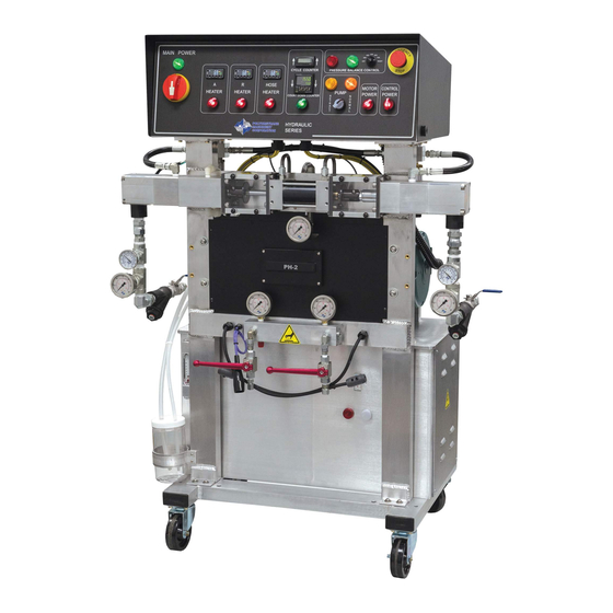
PH/PHX-2
Proportioner
For Professional Use Only
Not approved for use in European
explosive atmosphere locations
Manual
Ref. # MN-04009
Polyurethane Machinery Corp.
Corporate: 1 KOMO Drive, Lakewood, NJ 08701
Manufacturing: 2 KOMO Drive, Lakewood, NJ 08701
Phone: 732-415-4400
http://www.polymac-usa.com
Fax: 732-364-4025
Advertisement
Table of Contents

Related Manuals for PMC PH-2


Summary of Contents for PMC PH-2
- Page 1 PH/PHX-2 Proportioner For Professional Use Only Not approved for use in European explosive atmosphere locations junctioncrew.com Manual Ref. # MN-04009 Polyurethane Machinery Corp. Corporate: 1 KOMO Drive, Lakewood, NJ 08701 Manufacturing: 2 KOMO Drive, Lakewood, NJ 08701 REVISION 1.0 Phone: 732-415-4400 Fax: 732-364-4025 http://www.polymac-usa.com Before installing the PH Series Proportioner and start-up, carefully...
-
Page 2: Table Of Contents
PH/PHX-2 Manual TABLE OF CONTENTS WARRANTY ........................4 SAFETY AND HANDLING ..................... 6 CHARACTERISTICS ...................... 8 Principal Heating System ..................... 8 Hose Heating System ....................8 Double Acting Opposed Piston Metering Pumps ............8 Pressure Balance Control System ................9 TECHNICAL SPECIFICATIONS .................. - Page 3 PH/PHX-2 Manual HYDRAULIC OIL SPECIFICATIONS ................51 REPLACEMENT KITS ....................52 PARTS IDENTIFICATION .................... 53 FRAME ASSEMBLY ....................53 HYDRAULIC MANIFOLD ASSEMBLY ..............55 EXIT MANIFOLD ASSEMBLY ................... 56 HYDRAULIC SEAL ASSEMBLY ................57 HYDRAULIC PISTON ASSEMBLY ................58 HYDRAULIC CYLINDER ASSEMBLY ............... 59 A &...
-
Page 4: Warranty
Defective in material or workmanship, it is Customer’s responsibility to contact PMC and return the Product to PMC as directed by PMC, freight prepaid. If PMC determines that the Product is Defective and that such Defect is covered by this Warranty, PMC will credit Customer for the reasonable freight charges incurred by Customer in returning the Defective Product to PMC, and PMC (or its authorized agent) will, at PMC’s option, repair or replace the Product, subject to... - Page 5 Warranty for the remainder of original Warranty Period or for three (3) months from the repair or replacement date, whichever is longer. No Rights Implied: Nothing in the sale, lease or rental of any Product by PMC shall be junctioncrew.com construed to grant any right, interest or license in or under any patent, trademark, copyright, trade secret or other proprietary right or material owned by anyone;...
-
Page 6: Safety And Handling
Keep this Operations Manual for future consultation of useful information at all times. If you lose this manual, ask for a new copy from your PMC Service Center or go on line at our web site (www.polymac-usa.com). - Page 7 Always use liquids and solvents that are compatible with the unit. If in doubt, consult your authorized PMC distributor. When working with the PH Series Proportioner, it is recommended that the operator wear suitable clothing and elements of personal protection, including, without limitation, gloves, protective goggles, safety footwear and face masks.
-
Page 8: Characteristics
PH/PHX-2 Manual CHARACTERISTICS The PH Series Proportioner has been designed and built for the application of polyurea chemical systems, polyurethane foam chemical systems, and some specific two- component epoxy systems. Principal Heating System The Proportioner consists of one (1) Material Heater without internal seals. The Heater has three (3) Heating Elements per fluid side rated at 1,250, 1,500, or 1750 watts, each giving the Proportioner a total heat output of 7,500, 9,000, or 10,500 watts and the necessary control and safety components for their precise operation. -
Page 9: Pressure Balance Control System
PH/PHX-2 Manual Pressure Balance Control System The Pressure Balance Control (PBC) system performs an automatic shutdown when a chemical imbalance occurs. When the system is turned off, the Proportioner will perform as if there is no PBC system and will continue pumping material. When the system is turned on, it will continually monitor the pressure between the two chemicals (known as the pressure differential). -
Page 10: Technical Specifications
Main Voltage: __________________________________________3 x 208-230V, 50/60Hz Electrical Consumption: PH-2, 2000 PSI (2 x 3.75 kW Heaters) _______ 40 A @ 3 x 230V Electrical Consumption: PH-2, 2000 PSI (2 x 4.50 kW Heaters) _______ 46 A @ 3 x 230V Electrical Consumption: PH-2, 2000 PSI (2 x 5.25 kW Heaters) _______ 51 A @ 3 x 230V... -
Page 11: Mechanical
Manual Mechanical Maximum working pressure PH-2 (123 pumps): ___________ 2,000 psi (14 MPa, 138 bar) Maximum working pressure PHX-2 (61 pumps): ____________ 3,000 psi (21 MPa, 207 bar) Maximum production ratio 1:1 PH-2 (123 pumps): _______________ 31 lb/min (14 kg/min) Maximum production ratio 1:1 PHX-2 (61 pumps): ________________ 2.3 gpm (10.5 Lpm) -
Page 12: Description
PH/PHX-2 Manual DESCRIPTION junctioncrew.com PH-2/PHX-2 Proportioners... - Page 13 PH/PHX-2 Manual junctioncrew.com PH-2/PHX-2 Proportioners...
- Page 14 PH/PHX-2 Manual A. Control Panel Controls and regulates the operation of the PH Series Proportioner. B. Isocyanate (Iso, A) Metering Pump Meters the Isocyanate material. C. Polyol (Poly, R) Metering Pump Meters the Polyol material. D. Hydraulic Cylinder Assembly Transfers power from hydraulic pump to material pumps. E.
- Page 15 Temperature Controllers – Displays the temperature of the chemicals. See page 27 for detailed Temperature Controller instructions. U. Totalizer – Indicates the number of pump cycles to calculate material usage. MODEL PUMP SIZE CYCLES PER GALLON PH-2, 2000 PSI PHX-2, 3000 PSI...
- Page 16 PH/PHX-2 Manual V. Auto Shut Down Switch - Turns ON and OFF power to the Auto Shut Down unit. Auto Shut Down Counter – Used to set the amount of cycles required to prevent the chemical drums from running dry, the machine will shut down when the preset cycles expire.
-
Page 17: Installation
PH/PHX-2 Manual INSTALLATION WARNING! Use suitable protection and follow the recommendations in the Safety Information enclosed and provided by material suppliers when installing or working with the Proportioner. Inside the console is a Terminal Strip for connecting the incoming power cable (not supplied). The electrical connection of the Proportioner must be performed by a qualified electrician. - Page 18 PH/PHX-2 Manual Follow the recommended procedure in the indicated order to install the Proportioner: 1. Insert the main power cable by passing it through the wire stop at the bottom of the electrical console and connect as shown in the diagram above. 2.
- Page 19 Ensure Main Power Switch is OFF and incoming power is locked OFF before reversing power leads. Recheck rotation before proceeding with Installation. 5. Fill the Lube Reservoir with PMC Pump Lube or suitable diluents. It is not necessary to prime the system.
- Page 20 PH/PHX-2 Manual Heated Hose Installation CAUTION! The material delivery Heated Hoses are color coded Red and Blue allowing the user to recognize them. The Red corresponds to the Isocyanate (Iso, A) and the Blue to the Polyol (Poly, R). To avoid connection errors, the Coupling Connections of the Iso (A) and Poly (R) Heated Hoses are also different sizes to ensure correct orientation.
- Page 21 PH/PHX-2 Manual 5. It is recommended the TSU be installed between the last section of Heated Hose and the Gun Whip. Carefully straighten the sensing wire, inserting it in the Iso (A) Heated Hose and tighten fluid fittings with appropriate sized open-end wrenches. CAUTION! To protect the TSU sensor, you must pay special attention not to kink or excessively bend the Heated Hoses.
- Page 22 PH/PHX-2 Manual Hose Heat Transformer The Hose Heat Transformer offers the ability of connecting to different output voltages depending on the total length of the Heated Hose in use, maximizing the heating ability of the Heated Hose. The factory setting is 18 volts for use with 60 feet of Heated Hose. Before starting the Proportioner, ensure the setting matches the Heated Hose length installed.
- Page 23 PH/PHX-2 Manual 7. Connect the Transfer Pump/ Heated Hose Assemblies/ Air Supply and Air Dryer systems as required. Review the Installation Instructions for each to ensure proper set- up and operation. 8. Install the Material Transfer Pumps as follows: WARNING! If Transfer Pumps have been previously used, pay special attention to connect each Pump to “its”...
-
Page 24: Proportioner Purging
PH/PHX-2 Manual PROPORTIONER PURGING WARNING! Use suitable Personal Protection Equipment (PPE) and follow the recommendations in the Safety Information provided by product suppliers when installing or working with the unit. WARNING! Do not turn the Temperature Controllers ON until the Proportioner purging procedure is complete and the Primary Heaters and Heated Hoses are filled with material. - Page 25 PH/PHX-2 Manual Gauges (E, F, page 14) should approximately read the same. Check all Heated Hose Coupling connections for leakage. 11. Check all TSU and “Fast-Lock” connections for leaks. 12. Bundle all Heated Hose Connections ensuring that there are NO kinks in the TSU Cable or Air Hose.
-
Page 26: Pressure Balance Control
PH/PHX-2 Manual PRESSURE BALANCE CONTROL The PH Series Proportioner has been designed with a pressure balance control system. This system will give the operator of this machine the ability to control a pressure imbalance within certain predetermined parameters. The system consists of: Selector Switch Fault Light On Light... -
Page 27: Digital Temperature Controller
PH/PHX-2 Manual DIGITAL TEMPERATURE CONTROLLER The PH Series has three (3) Digital Temperature Controllers to manage the temperatures for the Primary Heaters and the Heated Hose. The Hose Heater Controller is programmed differently from the heater Controllers and therefore not interchangeable with them. -
Page 28: Start-Up
PH/PHX-2 Manual START-UP NOTE! Follow the recommended procedure in the order shown. CAUTION! The Start-up procedures assume that all steps in Proportioner purging have been performed and no problems were found. 1. Check the hydraulic fluid level and service as required. 2. - Page 29 Push in on the red button until the data is replicated on the top row, the top row will count down. Figure B MODEL CYCLES PER GALLON PH-2, 2000 PSI 123 pumps 23 cycles = 1 gallon PHX-2, 3000 PSI 61 pumps 47 cycles = 1 gallon c.
-
Page 30: Shut-Down
PH/PHX-2 Manual SHUT-DOWN TEMPORARY Follow the recommended procedure in the indicated order for Proportioner temporary shut- down such as lunch breaks. 1. Set Pump Switch (P, page 15) to OFF position. 2. Turn both “A” and “R” Heaters OFF. Hose Heater should remain ON. Never leave Proportioner ON if unattended. -
Page 31: Troubleshooting
PH Series Proportioner. The information provided will serve as a guideline to detect and resolve problems. In any case, feel free to contact your authorized PMC distributor, where a qualified technician will advise you. WARNING: Only qualified personnel should perform troubleshooting;... -
Page 32: Heaters
PH/PHX-2 Manual Heaters WARNING! Only qualified personnel should perform troubleshooting; unqualified personnel may cause damage to the unit, personnel, or property and put the operator at risk. The Heaters are components that reach high temperatures; you must wait until they cool before handling junctioncrew.com NOTE ! The Thermal Limit Switch is a safety switch in contact with the Heater... - Page 33 PH/PHX-2 Manual PROBLEM______________________________________________________________ Primary heater does not heat and the display on the controller shows ambient temperature. SOLUTIONS 1. Check that the light on the on/off switch is lit when the heater is turned on, if not replace the switch. If the light is on, move to the next step.
- Page 34 PH/PHX-2 Manual PROBLEM________________________________________________________________ Primary heater does not heat and the display on the controller shows an error message (SbEr, EEPE, CjEr, AdEr). SOLUTIONS 1. Check position 6 and 7 on the heater controller for loose wires. If the wires are tight move to the next step. 2.
-
Page 35: Hydraulic Drive System
PH/PHX-2 Manual Hydraulic Drive System Follow the recommended procedure in the indicated order to solve the problem and avoid unnecessary repairs. Make sure all Switches are in the correct position and Indicator Lights ON before determining the existence of a fault. WARNING! Before correcting any kind of defect, make sure the Main Power Switch is OFF and incoming power is locked OFF. - Page 36 PH/PHX-2 Manual PROBLEM_________________________________________________________________ Hydraulic Pump does not develop pressure. SOLUTIONS 1. Hydraulic Power Package NOTE! Hydraulic pressure is not generated if the Motor Power Switch (X, page 12) is OFF or the Pump Switch (Y, page 12) is in the OFF position. With the Pump Switch in the NORMAL position, the failure of the Hydraulic Pump to develop pressure is loss of pump suction (prime).
-
Page 37: Metering Pump Line
PH/PHX-2 Manual Metering Pump Line NOTE: As seen from front of unit. Follow the recommended procedure in the indicated order to solve the problem and avoid unnecessary repairs. Make sure all Switches are in the correct position and Indicator Lights ON before determining the existence of a fault. junctioncrew.com PROBLEM ____________________________________________________________ Metering pumps do not change direction and the pressures on both of chemical gauges are... - Page 38 PH/PHX-2 Manual IF THE DIRECTIONAL INDICATOR LIGHT IS PROCEED BELOW BEFORE TROUBLESHOOTING, THE REVERSING PLATE MUST BE MOVED AWAY FROM THE SWITCH. a) Bleed down the chemical pressures. b) Ensure Pump Switch (X, page 16) is OFF. c) Turn on the motor (W, page 16). d) Go to the Directional Valve and locate the Actuation Coils.
- Page 39 PH/PHX-2 Manual 3. Safety Pressure Switch Each Metering Pump has a Safety Pressure Switch set to 2,200 psi. for #123 pumps, 3,200 psi for #61 pumps. When the material system reaches this pressure, the Safety Pressure Switch will remove power from the Directional Valve and Direction Indicator Lights (Q, page 15).
- Page 40 PH/PHX-2 Manual 5. Cavitations Cavitations occur when the Metering Pump (B or C, page 14) requires a larger volume of material than the supply system (Transfer Pump) can furnish. This creates a "void" of material in the Metering Pump. The most common causes of cavitations are: a) Material temperature too low causing increased material viscosity resulting in the inability of the Transfer Pump to maintain sufficient supply to the Metering Pump.
-
Page 41: Hose Heating
PH/PHX-2 Manual Hose Heating WARNING! Before correcting any kind of defect, make sure the Main Power Switch is OFF and incoming power is locked OFF. NEVER access the inside of the Control Panel with the Proportioner power supply ON. The Heated Hose are components which reach high temperatures;... - Page 42 PH/PHX-2 Manual and see if the hose heat circuit is operating; if so replace the whip. To take a continuity reading through the heated hose, one of the leads from the transformer to the “A” or “R” heated hose must be disconnected. If no voltage is coming out of the transformer to the heated hose move on to the next step.
- Page 43 PH/PHX-2 Manual PROBLEM______________________________________________________________ Heated hose controller shows excessive temperature SOLUTIONS 1. Set the controller set point at least 20 degrees lower than the temperature shown on the controller. Briefly turn on the hose and look for the led light on the solid state relay to be on.
-
Page 44: Pressure Balance Control
ON light turns off, and the FAULT light turns on), but the pumps do not shut off, check for continuity between contacts 11 and 12 on CR1. If there is continuity, contact your authorized PMC distributor. If there is discontinuity, proceed to the next step. -
Page 45: Maintenance
Make sure that all of the safety protections are correctly fitted after all repair or maintenance work. CAUTION! All repairs performed by unqualified personnel or the use of parts other than supplied by PMC may cause damage to the unit and put the operator risk. -
Page 46: Inlet Material Screens
PH/PHX-2 Manual Inlet Material Screens Inspection of the Inlet Material Screens on a daily basis is no longer necessary as long as the following conditions are met. 1. Material drums are stored within the recommended material storage temperature range and drums are not opened prior to installing the Proportioner Material Transfer Pumps. -
Page 47: Hydraulic Drive System
PH/PHX-2 Manual Hydraulic Drive System WARNING! Before performing any maintenance, make sure the Main Power Switch is OFF and incoming power is locked OFF. The Hydraulic Unit is a component that works under pressure. Do not open any connection or carry out maintenance on components subject to pressure until all pressure has been bled to zero. -
Page 48: Metering Pump Line
PH/PHX-2 Manual Metering Pump Line WARNING! Before performing any maintenance, make sure the Main Power Switch is OFF and incoming power is locked OFF. Allow material temperature to cool below 80F and bleed all material pressure to zero. Weekly: When the Proportioning Pumps are functioning properly it is not unusual for a small amount of Poly (R) material to appear on the Pump Shaft. -
Page 49: Material Heater
PH/PHX-2 Manual Material Heater WARNING! Before performing any maintenance, make sure the Main Power Switch is OFF and incoming power is locked OFF. NEVER access the inside of the Control Panel with the Proportioner power supply ON. The Heaters are components that reach high temperatures;... - Page 50 PH/PHX-2 Manual WARNING! Before performing any maintenance, make sure the Main Power Switch is OFF and incoming power is locked OFF. NEVER access the inside of the Control Panel with the Proportioner power supply ON. The Heaters are components that reach high temperatures; you must wait until they have cooled before handling and bleed all material pressure to zero.
-
Page 51: Hydraulic Oil Specifications
PH/PHX-2 Manual HYDRAULIC OIL SPECIFICATIONS Recommended Hydraulic Oil Specification: ISO/ASTM Viscosity Grade 32 Viscosity: 28.8 – 35.2 SSU@ 104 F Rust and Oxidation Inhibited Manufacturers: Mobil DTE24 (Recommended) Cook’s Albavis 8 Ashland-Valvoline AW15 Shell – Tellus 32(25) ... -
Page 52: Replacement Kits
PH/PHX-2 Manual REPLACEMENT KITS HYDRAULIC CYLINDER REBUILD KIT (KT-05200) Part Number Description HI-05025-1 U-Cup HI-05025-2 Back-up Ring, Piston HI-05025-3 Wear Ring HI-05025-4 Rod Wiper HI-05025-5 Shaft Seal HI-05025-6 Back-up Ring, Bushing OR-00039A O-ring OR-00040A O-ring HEATER THERMOCOUPLE KIT (KT-05021) Part Number Description junctioncrew.com HI-05020... -
Page 53: Parts Identification
PH/PHX-2 Manual PARTS IDENTIFICATION FRAME ASSEMBLY junctioncrew.com... - Page 54 PH/PHX-2 Manual FRAME ASSEMBLY FR-10 ITEM PART NUMBER DESCRIPTION HI-00014-04A TANK TOP GASKET HI-05317 3/8” JIC BULKHEAD UNION HI-05306 TANK PUMP DRAIN TUBE HI-05319 1/2” JIC BULKHEAD UNION HI-05308 TANK DISCHARGE TUBE EL-05230-03 RT ANGLE CONDUIT CONNNECTOR MQ-01008A LUBE BOTTLE BRACKET HI-00001A SIGHT GAUGE EL-05233...
-
Page 55: Hydraulic Manifold Assembly
PH/PHX-2 Manual HYDRAULIC MANIFOLD ASSEMBLY junctioncrew.com HYDRAULIC MANIFOLD ASSEMBLY HI-05335 ITEM PART NUMBER DESCRIPTION HI-05070-3 HYDRAULIC MANIFOLD HI-05007 6 ORB X 6 JIC HI-05324 6 ORB X ½ JIC; 90 DEG HI-05348 6 ORB EXTENTION HI-05350 6 JIC 6 ORB "T" HI-05040 PRESSURE GAUGE 0-2000 PSI HI-05006-6... -
Page 56: Exit Manifold Assembly
PH/PHX-2 Manual EXIT MANIFOLD ASSEMBLY Hose Configurations Forward Underside junctioncrew.com EXIT MANIFOLD ASSEMBLY HI-05331 – LOW PRESSURE HI-05343 – HIGH PRESSURE ITEM QTY PART NUMBER DESCRIPTION HI-05307 OUTLET MANIFOLD HI-05011 6 ORB X 6 JIC N HI-05036 1/4 NPT FLUSH SEAL PIPE PLUG HI-05329 6 ORB X 5 JIC EL-195... -
Page 57: Hydraulic Seal Assembly
PH/PHX-2 Manual HYDRAULIC SEAL ASSEMBLY junctioncrew.com HYDRAULIC SEAL ASSEMBLY ITEM PART NUMBER DESCRIPTION HI-05025-13 BUSHING; ROD HI-05025-4 ROD WIPER HI-05025-5 SHAFT SEAL HI-05025-6 BACK-UP RING; BUSHING OR-00039A O-RING #218 HYD CYLINDER ROD... -
Page 58: Hydraulic Piston Assembly
PH/PHX-2 Manual HYDRAULIC PISTON ASSEMBLY junctioncrew.com HYDRAULIC PISTON ASSEMBLY ITEM PART NUMBER DESCRIPTION HI-05300 HYDRAULIC PISTON HI-05025-3 WEAR RING HI-05025-2 BACK UP RING; PISTON HI-05025-1 U CUP... -
Page 59: Hydraulic Cylinder Assembly
PH/PHX-2 Manual HYDRAULIC CYLINDER ASSEMBLY junctioncrew.com... - Page 60 PH/PHX-2 Manual HYDRAULIC CYLINDER ASSEMBLY HI-05336 ITEM PART NUMBER DESCRIPTION HYDRAULIC PISTON ASSEMBLY (SEE PAGE 58) HI-05301 HYDRAULIC CYLINDER HI-05200-3 PORT BLOCK; HYDRAULIC HYDRAULIC SEAL ASSEMBLY (SEE PAGE 56) HI-05302 FEMALE CLEVIS HI-05303 SWITCH PLATE OR-00040A O-RING #036 HYD CYLINDER HI-05332 FLANGE RTAINER, “A”...
-
Page 61: A & R Single Pump Assembly (16:1)
PH/PHX-2 Manual A & R SINGLE PUMP ASSEMBLY (16:1) A & R SINGLE PUMP ASSEMBLY PA-044 PART ITEM DESCRIPTION NUMBER PA-057 CAP SCREW OUTLET BODY junctioncrew.com SEE PAGE 62 ASSEMBLY PISTON SEE PAGE 63 ASSEMBLY INLET BODY SEE PAGE 64 ASSEMBLY... -
Page 62: Pa-044 Outlet Body Assembly
PH/PHX-2 Manual PA-044 OUTLET BODY ASSEMBLY OUTLET BODY ASSEMBLY PA-044 PART ITEM QTY DESCRIPTION NUMBER junctioncrew.com PA-045 OUTLET BODY ROD SEAL PA-052 ASSEMBLY PA-051 ROD BUSHING PA-064 PACKING NUT PA-065 SCRAPER SEAL... -
Page 63: Pa-044 Piston Assembly
PH/PHX-2 Manual PA-044 PISTON ASSEMBLY PISTON ASSEMBLY PA-044 PART ITEM QTY DESCRIPTION NUMBER PA-047 PISTON junctioncrew.com PA-062 FLUID ROD PA-046 PISTON VALVE OR-916 O-RING PA-048 3/4" CHROME BALL PA-049 SPRING PA-050 SPRING RETAINER... -
Page 64: Pa-044 Inlet Body Assembly
PH/PHX-2 Manual PA-044 INLET BODY ASSEMBLY INLET BODY ASSEMBLY PA-044 PART ITEM QTY DESCRIPTION NUMBER PA-053 INLET BODY PA-055 PISTON BUSHING junctioncrew.com PA-054 PISTON SEAL ASSEMBLY OR-035 O-RING PA-060 BALL STOP PA-061 FOOT VALVE SPRING PA-059 1" BALL OR-920 O-RING PA-058 INLET VALVE... -
Page 65: A & R Single Pump Assembly (30:1)
PH/PHX-2 Manual A & R SINGLE PUMP ASSEMBLY (30:1) A & R SINGLE PUMP ASSEMBLY PAX-044 PART ITEM DESCRIPTION NUMBER PA-057 CAP SCREW OUTLET junctioncrew.com BODY SEE PAGE 66 ASSEMBLY PISTON SEE PAGE 67 ASSEMBLY INLET BODY SEE PAGE 68 ASSEMBLY... -
Page 66: Pax-044 Outlet Body Assembly
PH/PHX-2 Manual PAX-044 OUTLET BODY ASSEMBLY OUTLET BODY ASSEMBLY PAX-044 PART ITEM QTY DESCRIPTION NUMBER junctioncrew.com PAX-045 OUTLET BODY PAX-064 PACKING NUT PAX-065 SCRAPER SEAL PAX-051 ROD BUSHING ROD SEAL PAX-052 ASSEMBLY... -
Page 67: Pax-044 Piston Assembly
PH/PHX-2 Manual PAX-044 PISTON ASSEMBLY PISTON ASSEMBLY PAX-044 PART ITEM QTY DESCRIPTION NUMBER junctioncrew.com PAX-047 PISTON PAX-062 FLUID ROD PAX-046 PISTON VALVE PAX-049 SPRING PAX-059 1/2" BALL PAX-050 SPRING RETAINER OR-116 O-RING... -
Page 68: Pax-044 Inlet Body Assembly
PH/PHX-2 Manual PAX-044 INLET BODY ASSEMBLY INLET BODY ASSEMBLY PAX-044 ITEM QTY PART NUMBER DESCRIPTION PAX-053 INLET BODY junctioncrew.com PAX-055 PISTON BUSHING PA-052 ROD SEAL ASSEMBLY OR-030 O-RING PAX-058 INLET VALVE PA-048 3/4" BALL PAX-061 SPRING; FOOT VALVE PA-050 SPRING RETAINER OR-916 O-RING... -
Page 69: Pumpline Assembly
PH/PHX-2 Manual PUMPLINE ASSEMBLY junctioncrew.com... - Page 70 PH/PHX-2 Manual PUMP LINE ASSEMBLY PL-9 ITEM PART NUMBER DESCRIPTION PA-044 SINGLE PL-PA PUMP (SEE PAGE 61) PU-07007 BRACKET, PA PUMP FLOOR STOCK ¼-20 X 1 HEX SHCS HI-05334 FLANGE, PA FLOOR STOCK 3/8-16 X 3 HEX SHCS PU-07009 STAND OFF, PUMPLINE PU-07001 MALE CLEVIS PU-07003...
-
Page 71: Pumpline Assembly
PH/PHX-2 Manual PUMPLINE ASSEMBLY junctioncrew.com... - Page 72 PH/PHX-2 Manual PUMPLINE ASSEMBLY PL-10 ITEM PART NUMBER DESCRIPTION PAX-044 SINGLE PL-PAX PUMP (SEE PAGE 65) PU-07002 BRACKET, PAX FLOOR STOCK ¼-20 X 1 HEX SHCS HI-05338 FLANGE, PAX FLOOR STOCK 3/8-16 X 3 HEX SHCS PU-07009 STAND OFF, PUMPLINE PU-07001 MALE CLEVIS PU-07003...
-
Page 73: A" Inlet Manifold Assembly
PH/PHX-2 Manual “A” INLET MANIFOLD ASSEMBLY junctioncrew.com “A” INLET MANIFOLD ASEMBLY YS-6 ITEM PART NUMBER DESCRIPTION HI-05305 INLET MANIFOLD HI-05341 INLET MANIFOLD MOUNT FLOOR STOCK 1/4-20 X 5/8 FLAT COUNTERSUNK SHCS HI-05036 1/4 NPT FLUSH SEAL PIPE PLUG HI-05325 12 ORB X ¾ JIC HI-05315 12 ORB X ¾... -
Page 74: R" Inlet Manifold Assembly
PH/PHX-2 Manual “R” INLET MANIFOLD ASSEMBLY junctioncrew.com “R” INLET MANIFOLD ASSEMBLY YS-7 ITEM PART NUMBER DESCRIPTION FLOOR STOCK 1/4-20 X 5/8 FLAT COUNTERSUNK SHCS HI-05036 1/4 NPT FLUSH SEAL PIPE PLUG HI-05325 12 ORB X ¾ JIC HI-05315 12 ORB X ¾ JIC; 90 DEG HI-05316 ¾... -
Page 75: Preheater Assembly
PH/PHX-2 Manual PREHEATER ASSEMBLY junctioncrew.com... - Page 76 PH/PHX-2 Manual PREHEATER ASSEMBLY junctioncrew.com...
- Page 77 PH/PHX-2 Manual PREHEATER ASSEMBLY PH-21 (3750 W) PH-22 (4500 W) PH-23 (5250 W) ITEM PART NUMBER DESCRIPTION GM-07000 HEATER BODY HI-05020 THERMOCOUPLE NUT GM-07001 HEATER BLOCK MOUNT GM-07002 HEATER BLOCK SPACER GM-07003 PHENOLIC STANDOFF, HEATER BODY HI-05344 6 ORB X 6 JIC SW HI-05007 6 ORB X 6 JIC HI-05034...
-
Page 78: Motor Line Assembly (1 Phase)
PH/PHX-2 Manual MOTOR LINE ASSEMBLY (1 PHASE) junctioncrew.com... - Page 79 PH/PHX-2 Manual MOTOR LINE ASSEMBLY ML-2 (3HP; 1PH; 60HZ) ML-3 (5HP; 1PH; 60HZ) PART ITEM DESCRIPTION NUMBER EL-05221 ELECTRIC MOTOR; 3HP; 1PH; 60HZ (ML-2) EL-05222 ELECTRIC MOTOR; 5HP; 1PH; 60HZ (ML-3) HI-05001 BELL HOUSING HI-00065-02 MAGNALOY HUB HI-00065-01 MAGNALOY INSERT (ML-2) HI-00067 MAGNALOY INSERT 9.45HP (ML-3) HI-00065-03...
-
Page 80: Motor Line Assembly (3 Phase)
PH/PHX-2 Manual MOTOR LINE ASSEMBLY (3 PHASE) junctioncrew.com... - Page 81 PH/PHX-2 Manual MOTOR LINE ASSEMBLY ML-1 (3HP; 3PH; 60HZ) ML-4 (5HP; 3PH; 60HZ) PART ITEM DESCRIPTION NUMBER EL-05224 ELECTRIC MOTOR; 3HP; 3PH; 60HZ (ML-1) EL-05223 ELECTRIC MOTOR; 5HP; 3PH; 60HZ (ML-4) HI-05001 BELL HOUSING HI-00065-02 MAGNALOY HUB HI-00065-01 MAGNALOY INSERT (ML-1) HI-00067 MAGNALOY INSERT 9.45HP (ML-4) HI-00065-03...
-
Page 82: Final Assembly
PH/PHX-2 Manual FINAL ASSEMBLY junctioncrew.com... - Page 83 PH/PHX-2 Manual junctioncrew.com...
- Page 84 PH/PHX-2 Manual junctioncrew.com...
- Page 85 HEATER ASSY; PH(X)-2 (SEE PAGE 75) PH-23 HEATER ASSY; PH(X)-2 (SEE PAGE 75) HI-05331 EXIT MANIFOLD ASSY (SEE PAGE 56) PL-9 PUMPLINE, PH-2 (SEE PAGE 69) PL-10 PUMPLINE, PHX-2 (SEE PAGE 71) FLOOR STOCK 1/4" WASHER FLOOR STOCK 1/4-20 X 1 HEX BOLT...
- Page 86 SOLENOID VALVE CONNECTOR EL-00053 SOLENOID VALVE GASKET EL-158 MICRO CORDSET 90 DEGREE HI-05339 12 JIC X 16 JIC SW 90 DEG (PH-2) HI-05342 12 JIC X 12 NPTM 90 DEG (PHX-2) HI-05321 1/4 NPT X 1/2 TUBE 90 DEG EL-400-31...
-
Page 87: Hoses
PH/PHX-2 Manual HOSES junctioncrew.com HOSES ITEM PART NUMBER DESCRIPTION HI-05340 HOSE INLET TO PUMP HI-05047-1 HOSE 16.25" PUMP TO HEATER HI-05047-4 HOSE 9" HYDRAULIC PUMP TO TANK HI-05013 HYDRAULIC TANK RETURN HOSE; 1/2 X 15... -
Page 88: Exit Manifold Accessory
PH/PHX-2 Manual EXIT MANIFOLD ACCESSORY In Plant Option In Trailer Option junctioncrew.com KT-05300 ITEM QTY PART NUMBER DESCRIPTION HI-05011 6 ORB X 6 JIC EL-00051A-5 1/4 NPT X #6 SWIVEL GP-00100-2 BALL VALVE 1/4 5000PSI EL-00051A-4 1/4 NPT X #5 JIC EL-00051A-6 1/4 NPT X #6 JIC HI-05007... -
Page 89: Manual Revisions
PH/PHX-2 Manual MANUAL REVISIONS REVISION DATE CHANGES APPROVED 29-Jan-15 INITIAL RELEASE VADAMS junctioncrew.com...
Need help?
Do you have a question about the PH-2 and is the answer not in the manual?
Questions and answers