Table of Contents
Advertisement
Quick Links
Before installing the PH Series Proportioner and start-up, carefully
read all the technical and safety documentation included in this
manual. Pay special attention to the information in order to know and
understand the operation and the conditions of use of the PH Series
Proportioner. All of the information is aimed at improving user safety
and avoiding possible breakdowns from the incorrect use of the PH
Series Proportioner.
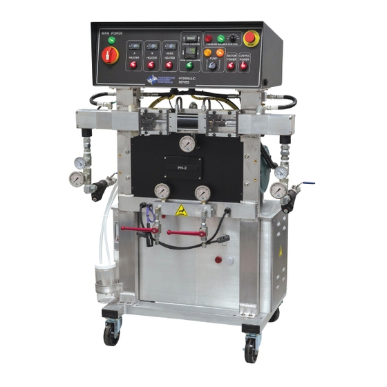
PH/PHX-2
Proportioner
For Professional Use Only
Not approved for use in European
explosive atmosphere locations
Electrical Diagrams
Ref. # MN-04011
Revision 4.0
May 2, 2016
Polyurethane Machinery Corp.
Corporate: 1 Komo Dr, Lakewood, NJ 08701
Manufacturing: 2 Komo Dr, Lakewood, NJ 08701
Phone: 732-415-4400
Fax: 732-364-4025
URL:
http://www.polymac-usa.com
Advertisement
Table of Contents

Related Manuals for PMC PH


Summary of Contents for PMC PH
- Page 1 Pay special attention to the information in order to know and understand the operation and the conditions of use of the PH Series Proportioner. All of the information is aimed at improving user safety and avoiding possible breakdowns from the incorrect use of the PH Series Proportioner.
-
Page 2: Table Of Contents
TABLE OF CONTENTS WARRANTY ........................... 1 SAFETY AND HANDLING ......................3 220 VAC – 1 PHASE ........................ 5 Component Identification ..........................5 Front Panel ..............................5 Bottom Plate ..............................7 Point to Point Diagrams ..........................10 Incoming Power............................. 10 Heater Circuit ..............................11 Motor Circuit .............................. - Page 3 400 VAC ..........................39 Component Identification ..........................39 Front Panel ..............................39 Bottom Plate ..............................41 Point to Point Diagrams ..........................44 Incoming Power............................. 44 Heater Circuit ..............................45 Motor Circuit ..............................46 24 VDC Power Circuit ............................ 47 Pump Circuit ..............................48 Pressure Balance Control Circuit ........................
-
Page 4: Warranty
Defective in material or workmanship, it is Customer’s responsibility to contact PMC and return the Product to PMC as directed by PMC, freight prepaid. If PMC determines that the Product is Defective and that such Defect is covered by this Warranty, PMC will credit Customer for the reasonable freight charges incurred by Customer in returning the Defective Product to PMC, and PMC (or its authorized agent) will, at PMC’s option, repair or replace the Product, subject to... - Page 5 No Rights Implied: Nothing in the sale, lease or rental of any Product by PMC shall be construed to grant any right, interest or license in or under any patent, trademark, copyright, trade secret or other proprietary right or material owned by anyone;...
-
Page 6: Safety And Handling
Keep this Operations Manual for future consultation of useful information at all times. If you lose this manual, ask for a new copy from your PMC authorized distributor or go online at our web site (www.polymac-usa.com). - Page 7 SAFETY AND HANDLING To prevent possible injury caused by incorrect handling of the raw materials and solvents used in the process, carefully read the Material Safety Data Sheet (MSDS) provided by your supplier. Deal with waste caused according to current regulations. Pour éviter toute blessure causée par une mauvaise manipulation des matières premières et les solvants utilisés dans le processus, veuillez lire attentivement la fiche signalétique (MSDS) fournies par votre fournisseur.
-
Page 8: 220 Vac - 1 Phase
220 VAC – 1 Phase Component Identification Front Panel... - Page 9 220 VAC – 1 Phase COMPONENT LIST ITEM PART NUMBER DESCRIPTION EL-128-W SELECTION SWITCH; 3 POS; WHT EL-129-G SELECTOR SWITCH; GREEN EL-107 E-STOP PUSH TWIST EL-124 TOTALIZER; BATT OP EL-127 COUNTER EL-101 SWITCHED MODULE; 80A; 1 POLE EL-105 SELECTOR HANDLE; RED EL-103 DOOR MOUNTING KIT EL-100...
-
Page 10: Bottom Plate
220 VAC – 1 Phase Bottom Plate... - Page 11 220 VAC – 1 Phase...
- Page 12 220 VAC – 1 Phase COMPONENT LIST ITEM PART NUMBER DESCRIPTION EL-171 DIODE RECTIFIER; 1000V; 1A EL-172 RESISTOR; 220 OHM; 5%; 3W; MET EL-114 CIRCUIT BREAKER; 3A; 2 POLE; TYP EL-156-10 TERMINAL COVER 10MM/5.2MM EL-174 SS RELAY; 24 VDC EL-152 END STOP;...
-
Page 13: Point To Point Diagrams
220 VAC – 1 Phase Point to Point Diagrams Incoming Power... -
Page 14: Heater Circuit
220 VAC – 1 Phase Heater Circuit... -
Page 15: Motor Circuit
220 VAC – 1 Phase Motor Circuit... -
Page 16: Vdc Power Circuit
220 VAC – 1 Phase 24 VDC Power Circuit... -
Page 17: Pump Circuit
220 VAC – 1 Phase Pump Circuit... -
Page 18: Pressure Balance Control Circuit
220 VAC – 1 Phase Pressure Balance Control Circuit... -
Page 19: Ladder Diagrams
220 VAC – 1 Phase Ladder Diagrams Incoming Power... -
Page 20: Heater Circuit
220 VAC – 1 Phase Heater Circuit... -
Page 21: Motor Circuit
220 VAC – 1 Phase Motor Circuit... -
Page 22: Vdc Power Circuit
220 VAC – 1 Phase 24 VDC Power Circuit... -
Page 23: Pump Circuit
220 VAC – 1 Phase Pump Circuit... -
Page 24: Pressure Balance Control Circuit
220 VAC – 1 Phase Pressure Balance Control Circuit CONTROL UNIT... -
Page 25: 220 Vac - 3 Phase
220 VAC – 3 Phase 220 VAC – 3 Phase Component Identification Front Panel... - Page 26 220 VAC – 3 Phase COMPONENT LIST ITEM PART NUMBER DESCRIPTION EL-128-W SELECTION SWITCH; 3 POS; WHT EL-129-G SELECTOR SWITCH; GREEN EL-107 E-STOP PUSH TWIST EL-124 TOTALIZER; BATT OP EL-127 COUNTER EL-105 SELECTOR HANDLE; RED EL-103 DOOR MOUNTING KIT EL-100 ROTARY DISCONNECT;...
-
Page 27: Bottom Plate
220 VAC – 3 Phase Bottom Plate... - Page 28 220 VAC – 3 Phase...
- Page 29 220 VAC – 3 Phase COMPONENT LIST ITEM PART NUMBER DESCRIPTION EL-171 DIODE RECTIFIER; 1000V; 1A EL-172 RESISTOR; 220 OHM; 5%; 3W; MET EL-114 CIRCUIT BREAKER; 3A; 2 POLE; TYP EL-156-10 TERMINAL COVER 10MM/5.2MM EL-174 SS RELAY; 24 VDC EL-152 END STOP;...
-
Page 30: Point To Point Diagrams
220 VAC – 3 Phase Point to Point Diagrams Incoming Power... -
Page 31: Heater Circuit
220 VAC – 3 Phase Heater Circuit... -
Page 32: Motor Circuit
220 VAC – 3 Phase Motor Circuit... -
Page 33: Vdc Power Circuit
220 VAC – 3 Phase 24 VDC Power Circuit... -
Page 34: Pump Circuit
220 VAC – 3 Phase Pump Circuit... -
Page 35: Pressure Balance Control Circuit
220 VAC – 3 Phase Pressure Balance Control Circuit... -
Page 36: Ladder Diagrams
220 VAC – 3 Phase Ladder Diagrams Incoming Power... -
Page 37: Heater Circuit
220 VAC – 3 Phase Heater Circuit... -
Page 38: Motor Circuit
220 VAC – 3 Phase Motor Circuit... -
Page 39: Vdc Power Circuit
220 VAC – 3 Phase 24 VDC Power Circuit... -
Page 40: Pump Circuit
220 VAC – 3 Phase Pump Circuit... -
Page 41: Pressure Balance Control Circuit
220 VAC – 3 Phase Pressure Balance Control Circuit CONTROL UNIT... -
Page 42: 400 Vac
400 VAC 400 VAC Component Identification Front Panel... - Page 43 400 VAC COMPONENT LIST ITEM PART NUMBER DESCRIPTION EL-128-W SELECTION SWITCH; 3 POS; WHT EL-129-G SELECTOR SWITCH; GREEN EL-107 E-STOP PUSH TWIST EL-124 TOTALIZER; BATT OP EL-127 COUNTER EL-105 SELECTOR HANDLE; RED EL-103 DOOR MOUNTING KIT EL-100 ROTARY DISCONNECT; 80A; 3 POLE EL-129-R SELECTOR SWITCH;...
-
Page 44: Bottom Plate
400 VAC Bottom Plate... - Page 45 400 VAC...
- Page 46 400 VAC COMPONENT LIST ITEM PART NUMBER DESCRIPTION EL-171 DIODE RECTIFIER; 1000V; 1A EL-172 RESISTOR; 220 OHM; 5%; 3W; MET EL-186 SINGLE POLE 3 AMP, BREAKER EL-156-10 TERMINAL COVER 10MM/5.2MM EL-174 SS RELAY; 24 VDC EL-152 END STOP; 35MM EL-146 TERMINAL BLOCK;...
-
Page 47: Point To Point Diagrams
400 VAC Point to Point Diagrams Incoming Power... -
Page 48: Heater Circuit
400 VAC Heater Circuit... -
Page 49: Motor Circuit
400 VAC Motor Circuit... -
Page 50: Vdc Power Circuit
400 VAC 24 VDC Power Circuit... -
Page 51: Pump Circuit
400 VAC Pump Circuit... -
Page 52: Pressure Balance Control Circuit
400 VAC Pressure Balance Control Circuit... -
Page 53: Ladder Diagrams
400 VAC Ladder Diagrams Incoming Power... -
Page 54: Heater Circuit
400 VAC Heater Circuit... -
Page 55: Motor Circuit
400 VAC Motor Circuit... -
Page 56: Vdc Power Circuit
400 VAC 24 VDC Power Circuit... -
Page 57: Pump Circuit
400 VAC Pump Circuit... -
Page 58: Pressure Balance Control Circuit
400 VAC Pressure Balance Control Circuit CONTROL UNIT...
Need help?
Do you have a question about the PH and is the answer not in the manual?
Questions and answers