BendPak HDSO-14P Operation Manual
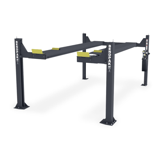
Four-post open front alignment lifts commercial grade 14,000 lbs. capacity
Hide thumbs
Also See for HDSO-14P:
- Installation and operation manual (56 pages) ,
- Service manual (40 pages) ,
- Installation and operation manual (60 pages)
Table of Contents
Advertisement
Quick Links
EUROPEAN USERS
400V 50Hz SUPPLY DETAILS ARE
INCLUDED WITH ELECTRICAL
CONTROL BOX. DISREGARD SUPPLY
WIRING DETAILS IN THIS MANUAL
INSTALLATION AND OPERATION MANUAL
FOUR-POST OPEN FRONT ALIGNMENT LIFTS
COMMERCIAL GRADE
14,000 LBS. CAPACITY
Models:
• HDSO-14P
• HDSO-14AX
RECEIVING
The shipment should be thoroughly inspected as soon as it is
received. The signed Bill of Lading is acknowledgement by
the shipping carrier as receipt of this product as listed in your
invoice as being in a good condition of shipment. If any of
these goods listed on this Bill of Lading are missing or dam-
aged, do not accept goods until the shipping carrier makes a
notation on the freight bill of the missing or damaged goods.
Do this for your own protection.
IMPORTANT SAFETY INSTRUCTIONS
SAVE THESE INSTRUCTIONS
PLEASE READ THE ENTIRE CONTENTS OF THIS MANUAL PRIOR TO
INSTALLATION AND OPERATION. BY PROCEEDING WITH LIFT INSTALLATION
AND OPERATION YOU AGREE THAT YOU FULLY UNDERSTAND AND
COMPREHEND THE FULL CONTENTS OF THIS MANUAL. FORWARD THIS
MANUAL TO ALL OPERATORS. FAILURE TO OPERATE THIS EQUIPMENT AS
DIRECTED MAY CAUSE INJURY OR DEATH.
BE SAFE
Your new lift was designed and built with safety in mind.
However, your overall safety can be increased with proper
training and thoughtful operation on the part of the operator.
DO NOT operate or repair this equipment without reading this
manual and the important safety instructions shown inside.
Keep this operation manual near the lift at all times. Make sure
that ALL USERS read and understand this manual.
Revision B – November 2020
Part Number 5900001
Keep this operation manual near the
machine at all times. Make sure that
ALL USERS read this manual.
Advertisement
Table of Contents

Related Manuals for BendPak HDSO-14P


Summary of Contents for BendPak HDSO-14P
- Page 1 Part Number 5900001 INSTALLATION AND OPERATION MANUAL FOUR-POST OPEN FRONT ALIGNMENT LIFTS COMMERCIAL GRADE 14,000 LBS. CAPACITY Models: • HDSO-14P • HDSO-14AX Keep this operation manual near the machine at all times. Make sure that ALL USERS read this manual. RECEIVING...
-
Page 2: Warranty / Serial Number Information
Our comprehensive product warranty means more than a commitment to you; it’s also a commitment to the value of your new BendPak lift. For full warranty details and to register your new lift contact your nearest BendPak dealer or visit: http:/ /www.bendpak.com/support/warranty/... -
Page 3: Definitions Of Hazard Levels
Our willingness to assist in uct or property damage. helping you process your claim does not make BendPak responsible for collection of claims or replacement of lost or damaged materials. -
Page 4: Table Of Contents
TABLE OF CONTENTS Warranty / Serial Number Information ............. . .2 Definitions of Hazard Levels . -
Page 5: Installers / Operators Agreement / Protective Equipment
I understand that Bendpak lifts are designed to be installed in indoor locations only. Failure to follow Eye protection is essential during installation installation instructions may lead to serious personal and operation activities. -
Page 6: Safety / Warning Instructions
INTRODUCTION 1. Carefully remove the crating and packing 2. Check the voltage, phase and proper amperage materials. CAUTION! Be careful when cutting steel requirements for the motor shown on the motor plate. banding material as items may become loose and fall caus- Wiring should be performed by a certified electrician only. -
Page 7: Step 1 / Selecting Site
28 days minimum. IMPORTANT NOTE: BendPak lifts are supplied with installation instructions and concrete fasteners meeting the criteria as prescribed by the American National Standard "Automotive Lifts - Safety Requirements for Construction, Testing, and Validation" ANSI/ALI ALCTV-2011. Lift buyers are responsible for any special regional structural and/or seismic anchoring requirements specified by any other agencies and/or codes such as the Uniform Building Code (UBC) and/or International Building Code (IBC). -
Page 8: Assembly View / Description Of Parts
When removing the lift from shipping angles pay close attention as the runways can slide and can cause injury. Prior to removing the bolts make sure the runways are held securely by a fork lift or some other heavy lifting device. Large Window Small Window Cross Tube... -
Page 9: Floor Plan / Specifications
FLOOR PLAN * IMPORTANT NOTE * Check diagonal measurements to confirm square layout; diagonal measurements must be equal. Model HDSO-14P HDSO-14AX Lifting Capacity 14,000 lbs / 6350 kg 14,000 lbs / 6350 kg A - Overall Width / Front 143” / 3638 mm 143”... -
Page 10: Clearances
CLEARANCES d. The difference is the estimated amount of shim 1. Lift Location: Use architects plan and Engineers thickness needed at each column. automatic level (transit) when available to locate lift. The above shows clearances of a typical bay layout. Lift floor Note: Maximum shim thickness is 1/2”... -
Page 12: Step 3 / Column And Cross Tube Installation
A maximum shim thickness of 2” is pos- sible by ordering optional shim plates. Contact your authorized BendPak Distributor for ordering information. Fig. 3.4 3. Using a forklift or crane, raise the Cross tubes (making sure the Plastic Slide Blocks and Buttons are still in position) and drop down into the top of the Columns. -
Page 13: Step 4 / Anchoring The Columns
STEP 4 Fig. 3.5 (Anchoring The Columns) IMPORTANT NOTE: BendPak lifts are supplied with installation instructions and concrete fasteners meeting the criteria as prescribed by the American National Standard "Automotive Lifts - Safety Requirements for Construction, Testing, and Validation" ANSI/ALI ALCTV-2011. -
Page 14: Step 5 / Raising The Cross Tubes
2. Manually raise the Cross Tubes until the primary Safety Locks Fig. 4.3 engage and rest on the lock position second down from the top of the ladder or approximately 66” off the ground. It is impor- tant that the SLACK SAFETY LOCK IS CLEARED. The Slack Safety Lock must never rest on the Safety Ladder. -
Page 15: Step 6 / Powerside Runway Installation
STEP 6 STEP 7 (Powerside Runway Installation) (Offside Runway Installation) 1. Locate the Powerside Runway easily identified by the 1. Position the Offside Runway on top of the Cross Tubes Cylinder and Sheave Roller mounting structures welded on the with the utility rail located inside. (See Fig. 7.1) underside. - Page 16 Model Part # Description HDSO-14P/14AX 5595065 HDSO-14P/14AX/14LSXE, HDS-14X CABLE ASSEMBLY Ø12 x 4,100 mm ST HDSO-14P/14AX 5595066 HDSO-14P/14AX/14LSXE, HDS-14X CABLE ASSEMBLY Ø12 x 5,732 mm ST HDSO-14P/14AX 5595089 HDSO-14P/14AX CABLE ASSEMBLY Ø12 x 11,302 mm ST...
-
Page 17: Step 8 / Cable Sheave Installation
STEP 8 STEP 9 (Cable / Sheave Installation) (Cable Installation) DO NOT PROCEED unless visual confirmation is made of ALL safety locks. ALL locks MUST be engaged before Failure to route lifting cables as described may lead proceeding. Failure to comply with these instructions may to serious personal injury and/or death to operator or result in severe personal injury or death. -
Page 18: Step 10 / Power Unit Installation
STEP 10 (Power Unit Installation) 1. Mount the Power Unit, Air Valve Mounting Bracket, Vibration Dampner, and Flex Tube Mounting Bracket to the Power Unit Mounting Bracket using the M8 hex bolts and Nylock Nuts. Fill the reservoir with 12 quarts of 10-WT hydraulic oil or Dexron automatic transmission fluid. -
Page 19: Step 11 / Routing Hydraulic Hoses
The standard Power Unit for your lift is 220 volt, 60HZ, single phase. All wiring must be performed by a certified electrician only. PROPER WIRING INSTRUCTIONS ARE AFFIXED TO MOTOR. DO NOT run Power Unit with no oil. Damage to pump can occur. The Power Unit must be kept dry. - Page 20 Fig 11.5 90° Air Line Compression Fitting 90° Air Line Compression Fitting 90° O-Ring Fitting 5. Route both the Power Unit Hydraulic Hose and TWO (2) lengths of Air Line through the Flex Hose. (See Fig. 11.6) Fig. 11.2 Fig 11.6 2.
-
Page 21: Step 12 / Routing Air Lines
STEP 12 7. Connect the hydraulic hose and air line as shown below making sure the hydraulic hose passes through the retain- ( Routing Air Lines) ing rings. MAKE SURE HOSES ARE KEPT CLEAR OF CABLES. There will be one air line hose left unconnected in 1. - Page 22 SAFETY AIR LINE ROUTING NOTE: CUT THE PROVIDED 1/4” AIR LINE TUBING WITH A SHARP BLADE TO LENGTHS AS REQUIRED. TUBING MUST BE CUT SQUARE WITH ALL PLASTIC BURRS REMOVED. AIR TUBING ASSEMBLY: SEE PAGE 19 FOR ASSEMBLY OF AIR LINE TUBING INTO FITTING. CAUTION: REMOVING THE AIR TUBING FROM THE COMPRESSION FITTINGS WILL CAUSE DAMAGE TO THE TUBING ITSELF.
- Page 23 DO NOT PERFORM ANY MAINTENANCE OR INSTALLATION OF ANY COMPONENTS WITHOUT FIRST ENSURING THAT ELECTRICAL POWER HAS BEEN DISCONNECTED AT THE SOURCE OR PANEL AND CANNOT BE RE-ENERGIZED UNTIL ALL MAINTENANCE AND/OR INSTALLATION PROCEDURES ARE COMPLETED. IMPORTANT POWER-UNIT INSTALLATION NOTES n DO NOT run power unit with no oil.
-
Page 25: Step 13 / Power Unit Hook Up
STEP 14 STEP 13 (Inspecting The Slack Safety Springs) (Power Unit Hook Up) 1. Have a certified electrician run the Power Supply to motor. Refer to the data plate found on the motor for proper power supply and wire size. The following steps involve the SLACK CABLE SAFETY DEVICE and MAIN SAFETY. -
Page 26: Step 16 / Attaching Approach Ramps / Tire Stops
5. Check to make sure that all Slack Safety Locks are cleared and free. (See Fig. 15.1) KEEP HANDS AND FEET CLEAR. Remove hands and feet from any moving parts. Keep feet clear of lift when lowering. Avoid pinch points. 9. -
Page 27: Step 17 / Leveling/Synchronizing
NOTE: Use a pencil, marking pen or attach a paper clip M14 Hex Bolts, onto the target scale at the crosshair reference. Nuts and Washers Fig. 17.1 Fig. 16.3 Alignment Rollback Turnplate Ramp Spacer Riser 6. Next, move the target and place it at point “B” on the runway. -
Page 28: Step 18 / Adding Grease
Safety locks may not engage at exactly the same time Wheels Chock must be used on the when vehicles are being raised. They should be close. Be rear wheels. (See Fig 18.1) sure that all four corners have passed the SAME safety ladder bar slot before lowering lift on the safety locks. -
Page 29: Optional Equipment Installation
OPTIONAL EQUIPMENT INSTALLATION Rolling Jack maximum weight capacity for use with HDSO-14P or HDSO-14AX is 7,000 lb (3,175 kg) per unit. HDS/HDSO-14LSX Rolling Jack Air Line Kit Installation Part # 5174009 REV 03/21/2012 5174009 HD-9/12/14, HDS/HDSO-14LSX/LSXE AIR LINE KIT PART # Description Qty. -
Page 31: Step 19 / Operation Instructions
Use only qualified lift ser- (Lift Operation Safety) vice personnel and genuine BendPak parts to make repairs. • THOROUGHLY train all employees in use and care of lift, using manufacturer’s instructions and “Lifting It Right” and “Safety Tips”... -
Page 32: Step 20 / Lift Operation Safety
LIFT OPERATION SAFETY (CONT’D) • ALWAYS keep area around lift free of tools, debris, grease and oil. • NEVER overload lift. Capacity of lift is shown on nameplate affixed to the lift. VISUALLY CONFIRM THAT ALL PRIMARY SAFETY LOCKS ARE ENGAGED BEFORE ENTERING •... - Page 33 2. Check safety locks to ensure they are in good operating condition. Fig 19.1 3. Check cables and sheaves for wear. Replace worn parts as required with genuine BendPak parts. • Lubricate the slide blocks with general purpose grease. Heavy usage may require more frequent lubrication.
-
Page 34: Wire Rope Inspection And Maintenance
WIRE ROPE INSPECTION AND MAINTENANCE Lifting cables should be replaced every three - five years or when visible signs of damage are apparent. DO NOT USE LIFT WITH DEFECTIVE / WORN CABLES. Lifting cables should be maintained in a well-lubricated condition at all times. Wire rope is only fully protected when each wire strand is lubricated both internal and external. -
Page 35: Safe Lift Operation
Safe Lift Operation Automotive and truck lifts are critical to the operation and profitability of your business. The safe use of this and other lifts in your shop is critical in preventing employee injuries and damage to customer’s vehicles. By operating lifts safely you can ensure that your shop is profitable, productive and safe. - Page 36 t DO NOT leave the controls while the lift is still in motion. t DO NOT stand directly in front of the vehicle or in the bay when vehicle is being loaded or driven into position. t DO NOT Go near vehicle or attempt to work on the vehicle when being raised or lowered. REMAIN CLEAR of lift when raising or lowering vehicle.
- Page 37 LIFT WILL NOT RAISE POSSIBLE CAUSE 1. Air in oil, (1,2,8,13) 2. Cylinder binding, (9) 3. Cylinder leaks internally, (9) 4. Motor run backward under pressure, (11) 5. Lowering valve leaks, (3,4,6,10,11) 6. Motor runs backwards, (7,14,11) 7. Pump damaged, (10,11) 8.
-
Page 38: Troubleshooting Guide
MOTOR WILL NOT RUN POSSIBLE CAUSE Fuse blown, (5,2,1,3,4) Limit switch burned out, (1,2,3,4) Microswitch burned out, (1,2,3,4) Motor burned out, (1,2,3,4,6) Voltage to motor incorrect, (2,1,8) REMEDY INSTRUCTION Check for correct voltage ......Compare supply voltage with voltage on motor nametag. - Page 39 WILL NOT RAISE LOADED LIFT POSSIBLE CAUSE 1. Air in oil, (1,2,3,4) 2. Cylinder binding, (5) 3. Cylinder leaks internally, (5) 4. Lift overloaded, (6,5) 5. Lowering valve leaks, (7,8,1,5,9) 6. Motor runs backwards, (10,12,9) 7. Pump damaged, (5,9) 8. Pump won’t prime, (1,2,3,4,5,11,9) 9.
- Page 40 LIFT WILL NOT STAY UP POSSIBLE CAUSE 1. Air in oil, (1,2,3) 2. Check valve leaks, (6) 3. Cylinders leak internally, (7) 4. Lowering valve leaks, (4,5,1,7,6) 5. Leaking fittings, (8) REMEDY INSTRUCTION 1. Check oil level ........The oil level should be up to the bleed screw in the reservoir with the lift all the way down.
- Page 44 MAINTENANCE RECORDS ____________________________________________________________________ ____________________________________________________________________ ____________________________________________________________________ ____________________________________________________________________ ____________________________________________________________________ ____________________________________________________________________ ____________________________________________________________________ ____________________________________________________________________ ____________________________________________________________________ ____________________________________________________________________ ____________________________________________________________________ ____________________________________________________________________ ____________________________________________________________________ ____________________________________________________________________ ____________________________________________________________________ ____________________________________________________________________ ____________________________________________________________________ ____________________________________________________________________ ____________________________________________________________________ ____________________________________________________________________...
Need help?
Do you have a question about the HDSO-14P and is the answer not in the manual?
Questions and answers