Table of Contents
Advertisement
Quick Links
Advertisement
Table of Contents

Related Manuals for Euroflex MB-flex S


Summary of Contents for Euroflex MB-flex S
- Page 1 Quick installation guide Conveyor system MB-flex S stainless steel...
- Page 2 GmbH. Subject to modification. … regarding this documentation or the system are to be sent to the address Suggestions and comments above. Last modification 17.11.2022 Quick installation guide_Conveyor system MB-flex S N_20221114_EN.docx...
-
Page 3: Table Of Contents
Protective enclosure/Protective cover ..................7 Spare parts and their purchase ....................8 Assembly ......................... 9 Overview of MB-flex S aluminium ................... 9 Assembly the slide profiles on the holding profiles ............... 10 3.2.1 Assembly the slide rails on the modular belt conveyor ..Fehler! Textmarke nicht definiert. -
Page 4: Reader Information
Infringement will lead to compensation for damages. Rights reserved for further claims. Quick installation guide_Conveyor system MB-flex S N_20221114_EN.docx... -
Page 5: Safety
These instructions should be repeated at appropriate intervals. ▪ Instruct the utilized personnel on handling the conveyor system. ▪ Equip the utilized personnel with the required protective equipment and check that it is worn at all times. Quick installation guide_Conveyor system MB-flex S N_20221114_EN.docx... -
Page 6: Instruction Of The Personnel
Qualified specialist personnel are persons who have obtained and proven special experience, knowledge and skills for the safe performance of tasks in particular specialist areas (e. g. mechanical, pneumatic, hydraulic, electrical) and who fulfil the following defined requirements. Quick installation guide_Conveyor system MB-flex S N_20221114_EN.docx... -
Page 7: Electricians
The protective enclosure/cover protects the operator and other persons from injuries caused by danger points inside the enclosure/cover. The owner is responsible for equipping the system with a protective enclosure/cover. Quick installation guide_Conveyor system MB-flex S N_20221114_EN.docx... -
Page 8: Spare Parts And Their Purchase
Spare parts and accessories can be ordered directly from the manufacturer via the following contact. Spare parts: Contact Designation Specification Company euroflex GmbH Street no. Hohe-Flum-Straße 62 Postcode, place 79650 Schopfheim Country Germany Telephone +49 (0) 7622/68453-00 +49 (0) 7622/68453-01 Email info@euroflexgmbh.de Quick installation guide_Conveyor system MB-flex S N_20221114_EN.docx... -
Page 9: Assembly
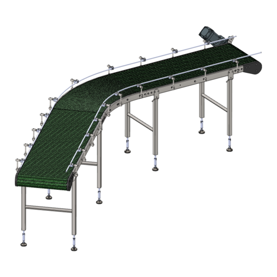
▪ Assembly the slide profiles on the holding profiles (Page 10) ▪ Assembling the modular chain belt (Page 13) Overview of MB-flex S stainless steel Fig. 1: Overview of MB-flex S stainless steel (example) Legend Designation Motor Side guide Modular chain belt... -
Page 10: Assembly The Slide Profiles On The Holding Profiles
During assembly, align the junction points of the components. ▪ Avoid steps between the junction points. 1. Check the slide profiles for damage. ǃ Only use undamaged slide profiles. 2. Chamfer the slide profiles at the start (viewed in running direction). Quick installation guide_Conveyor system MB-flex S N_20221114_EN.docx... - Page 11 13. Using a drill (drill bit ø 3,4 mm), drill a hole in the slide profile and the holding profile. ǃ Secure the profile with a support against bending! 14. Deburr after drilling and remove all chips. Quick installation guide_Conveyor system MB-flex S N_20221114_EN.docx...
- Page 12 (viewed in running direction). 20. At the end of the conveyor, mount the slide profile flush to the drive. Fig. 2: Mounting of the slide profiles on the holding profiles Quick installation guide_Conveyor system MB-flex S N_20221114_EN.docx...
-
Page 13: Assembling The Modular Chain Belt
6. At the assembly opening fit the connecting rod and close the chain with this. 7. Select the chain length so that the contraction of the chain ends is done with little effort. 8. Add a chain link if necessary. Quick installation guide_Conveyor system MB-flex S N_20221114_EN.docx... - Page 14 Subsequently press the blue closure PIN (2) from above into the opening over the tab until the PIN latches into place. Fig. 3: Assembling the modular chain belt Quick installation guide_Conveyor system MB-flex S N_20221114_EN.docx...
-
Page 15: Cleaning
Cleaning products containing chlorine, ammoniac, phosphoric acid or their compounds ▪ Abrasive cleaning products ▪ Solutions with a pH value below 4.5 or above 9 ▪ Water with a pressure above 20 bar ▪ Water with temperatures above 54°C Quick installation guide_Conveyor system MB-flex S N_20221114_EN.docx... -
Page 16: Preparation
52 °C to 54 °C. ǃ Inspect conveyor (sensory analysis: See, smell and feel) and ensure that dirt, cleaning agent, water and other residues have been rinsed away. ǃ Take care when using strong cleaning agents. Quick installation guide_Conveyor system MB-flex S N_20221114_EN.docx... - Page 17 Take care not to apply too much disinfectant so that the conveyor does not need to be rinsed. ǃ Remove excess disinfectant via the drain. ✓ Ready. Contact euroflex GmbH for instructions on cleaning any further contaminants. Quick installation guide_Conveyor system MB-flex S N_20221114_EN.docx...
-
Page 18: Maintenance
Every time after cleaning! Drive station, Spray! Deflection, Silicone spray Sliding bend, NSF H1 Every time after cleaning! Bending wheel Details on lubrication and maintenance see manufacturer of the Gear motor (Drive motor) gearmotor Quick installation guide_Conveyor system MB-flex S N_20221114_EN.docx... -
Page 19: Maintenance Plan
Use of non-original spare parts can lead to defects in the conveyance goods, operational malfunctions, loss of safety functions and damage to or destruction of components. » Only replace components with original spare parts from euroflex GmbH. General Assembly and maintenance work... - Page 20 Roller chain at the check for damage and elongation Maintenance personnel drive station thereafter every 500 Sprocket wheel on check for damage and wear 1,000 (quarterly) Maintenance personnel roller chain replace Replace if required Quick installation guide_Conveyor system MB-flex S N_20221114_EN.docx...
-
Page 21: Maintenance Log
In case of repairs at the conveyor system, the customer service will help (see page 4: Customer service). Spare parts can be ordered directly from the manufacturer (see page 8: Spare parts and their purchase). Personnel Specification Designation Personnel Maintenance personnel Quick installation guide_Conveyor system MB-flex S N_20221114_EN.docx... -
Page 22: Conveyor Chain: Repair Or Adjust The Chain Tension
50 OH, 250 OH, 500 OH, then check every 500 OH Replace after 4,000 OH Tools, aids Allen key Screwdriver Needle nose plier Prerequisite: ▪ System is switched off and safeguarded against being restarted. Quick installation guide_Conveyor system MB-flex S N_20221114_EN.docx... - Page 23 1. Loosen screws at the side parts of the deflection. 2. Remove side parts. 3. Lift the chain upwards. Remove fastening clip as follows: 4. Press the blue locking pin (1) upwards and remove. 5. Pull the yellow tab out. Quick installation guide_Conveyor system MB-flex S N_20221114_EN.docx...
- Page 24 11. Subsequently press the blue closure PIN (2) from above into the opening over the tab until the PIN latches into place. 12. Reattach and fasten the side parts. ✓ Ready. Fig. 4: Adjust modular belt chainAdjust modular belt chain Quick installation guide_Conveyor system MB-flex S N_20221114_EN.docx...
-
Page 25: Table Of Figures
Table of figures Table of figures Fig. 1: Overview of MB-flex S aluminium (example) ................9 Fig. 2: Mounting of the slide profiles on the holding profiles ............. 12 Fig. 3: Assembling the modular chain belt ..................14 Fig. 4: Adjust modular belt chainAdjust modular belt chain .............. 24...
Need help?
Do you have a question about the MB-flex S and is the answer not in the manual?
Questions and answers