Table of Contents
Advertisement
Quick Links
Advertisement
Table of Contents

Related Manuals for Euroflex EURO-flex


Summary of Contents for Euroflex EURO-flex
- Page 1 Quick installation guide Conveyor system EURO-flex aluminium...
- Page 2 GmbH. Subject to modification. … regarding this documentation or the system are to be sent to the address Suggestions and comments above. Last modification 11.11.2022 Quick installation guide_Conveyor system EURO-flex Al_20221111_EN.docx...
-
Page 3: Table Of Contents
Protective enclosure/Protective cover ..................7 Spare parts and their purchase ....................8 Assembly ......................... 9 Overview of EURO-flex aluminium ..................9 Assembly the slide rails on the link chain conveyor ............. 10 Assembling the link chain ..................... 13 Cleaning ......................... 14 Personnel and Protective equipment .................. -
Page 4: Reader Information
Infringement will lead to compensation for damages. Rights reserved for further claims. Quick installation guide_Conveyor system EURO-flex Al_20221111_EN.docx... -
Page 5: Safety
These instructions should be repeated at appropriate intervals. ▪ Instruct the utilized personnel on handling the conveyor system. ▪ Equip the utilized personnel with the required protective equipment and check that it is worn at all times. Quick installation guide_Conveyor system EURO-flex Al_20221111_EN.docx... -
Page 6: Instruction Of The Personnel
Qualified specialist personnel are persons who have obtained and proven special experience, knowledge and skills for the safe performance of tasks in particular specialist areas (e. g. mechanical, pneumatic, hydraulic, electrical) and who fulfil the following defined requirements. Quick installation guide_Conveyor system EURO-flex Al_20221111_EN.docx... -
Page 7: Electricians
The conveyor system must be equipped with a protective enclosure/cover in areas where there is a danger to persons. The protective enclosure/cover protects the operator and other persons from injuries caused by danger points inside the enclosure/cover. The owner is responsible for equipping the system with a protective enclosure/cover. Quick installation guide_Conveyor system EURO-flex Al_20221111_EN.docx... -
Page 8: Spare Parts And Their Purchase
Spare parts and accessories can be ordered directly from the manufacturer via the following contact. Spare parts: Contact Designation Specification Company euroflex GmbH Street no. Hohe-Flum-Straße 62 Postcode, place 79650 Schopfheim Country Germany Telephone +49 (0) 7622/68453-00 +49 (0) 7622/68453-01 Email info@euroflexgmbh.de Quick installation guide_Conveyor system EURO-flex Al_20221111_EN.docx... -
Page 9: Assembly
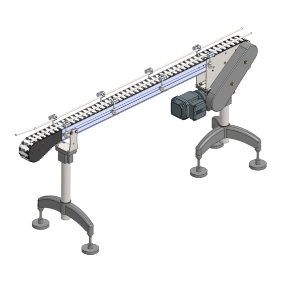
Overview of EURO-flex aluminium (Page 9) ▪ Assembly the slide rails on the link chain conveyor (Page 10) ▪ Assembling the link chain (Page 13) Overview of EURO-flex aluminium Fig. 1: Overview of EURO-flex aluminium (example) Legend Designation Link chain Side guide Motor... -
Page 10: Assembly The Slide Rails On The Link Chain Conveyor
Avoid slide rail connections at the connection points of the guide profiles. 1. Check the slide rail for damage. ǃ Only use undamaged slide rails. 2. Chamfer the slide rail at the start (viewed in running direction). Quick installation guide_Conveyor system EURO-flex Al_20221111_EN.docx... - Page 11 ǃ A distance of 10 mm must be maintained between the end of the slide rail and the bending wheel. ǃ The end of the slide rail may not curve upwards or downwards. Quick installation guide_Conveyor system EURO-flex Al_20221111_EN.docx...
- Page 12 22. Mount the slide rail at the end of the conveyor with a spacing of approx. 5 mm at the drive station. 23. Cut off the slide rail parallel to the drive station with the mitre cutter and gently deburr. Fig. 2: Assembly the slide rails Quick installation guide_Conveyor system EURO-flex Al_20221111_EN.docx...
-
Page 13: Assembling The Link Chain
4. Running direction (arrow direction) of the conveyor chain as shown in the illustration. Info With the system size EURO-flex 115 the running direction of the conveyor chain is opposite. Variant 1: 5. Insert the conveyor chain into the deflection. -
Page 14: Cleaning
Cleaning products containing chlorine, ammoniac, phosphoric acid or their compounds ▪ Abrasive cleaning products ▪ Solutions with a pH value below 4.5 or above 9 ▪ Water under high pressure ▪ Water with temperatures above 40°C Quick installation guide_Conveyor system EURO-flex Al_20221111_EN.docx... -
Page 15: Preparation
2. Remove contamination without damaging the surface. 3. Remove contamination with cleaning agents. 4. Rinse off solution with water under low pressure. 5. Rub surface to dry it. ✓ Ready. Contact euroflex GmbH for instructions on cleaning any further contaminants. Quick installation guide_Conveyor system EURO-flex Al_20221111_EN.docx... -
Page 16: Maintenance
Every time after cleaning! Drive station, Spray! Deflection, Silicone spray Sliding bend, NSF H1 Every time after cleaning! Bending wheel Details on lubrication and maintenance see manufacturer of the Gear motor (Drive motor) gearmotor Quick installation guide_Conveyor system EURO-flex Al_20221111_EN.docx... -
Page 17: Maintenance Plan
Use of non-original spare parts can lead to defects in the conveyance goods, operational malfunctions, loss of safety functions and damage to or destruction of components. » Only replace components with original spare parts from euroflex GmbH. General Assembly and maintenance work... - Page 18 Maintenance personnel Roller chain at the check for damage and elongation drive station thereafter every 500 Sprocket wheel on check for damage and wear e 1.000 (quarterly) Maintenance personnel roller chain replace Replace if required Quick installation guide_Conveyor system EURO-flex Al_20221111_EN.docx...
-
Page 19: Maintenance Log
In case of repairs at the conveyor system, the customer service will help (see page 4: Customer service). Spare parts can be ordered directly from the manufacturer (see page 8: Spare parts and their purchase). Personnel Specification Designation Personnel Maintenance personnel Quick installation guide_Conveyor system EURO-flex Al_20221111_EN.docx... -
Page 20: Conveyor Chain: Repair Or Adjust The Chain Tension
If one or more chain links are damaged, they must be replaced. If an uneven running or ambient noise occurs, it is necessary to shorten the chain belt. Select the chain length so that the contraction of the chain ends is done with little effort. Quick installation guide_Conveyor system EURO-flex Al_20221111_EN.docx... - Page 21 1. Place the steel pin in the intended recess and carefully knock out the chain bolt with the hammer. Fig. 4: Adjust link chain 2. Remove corresponding chain links or insert new ones. 3. Join the chain ends together. 4. Insert the chain bolt once more and carefully knock in. ✓ Ready. Quick installation guide_Conveyor system EURO-flex Al_20221111_EN.docx...
- Page 22 EURO- flex 85, 115, 195 a = min. 3,5 mm b = min. 3 mm EURO- flex 55 a = min. 2 mm b = min. 2,5 mm Fig. 5: Check conveyor chain for wear ✓ Ready. Quick installation guide_Conveyor system EURO-flex Al_20221111_EN.docx...
-
Page 23: Table Of Figures
Table of figures Table of figures Fig. 1: Overview of EURO-flex aluminium (example) ................. 9 Fig. 2: Assembly the slide rails ......................12 Fig. 3: Assembling the link chain ...................... 13 Fig. 4: Adjust link chain ........................21 Fig. 5: Check conveyor chain for wear ....................22...
Need help?
Do you have a question about the EURO-flex and is the answer not in the manual?
Questions and answers