
Related Manuals for Hill-Rom Trumpf Medical TruLight 1000


Summary of Contents for Hill-Rom Trumpf Medical TruLight 1000
- Page 1 Instruction manual TruLight™ 1000 examination light Read the instruction manual before using the product and store for later reference. English en-EN...
- Page 2 55000-00012_002_01 – 1695233 – 25/01/2018...
- Page 3 Thank you very much for buying the new TruLight™ 1000 lighting system. Please read through this instruction manual very carefully and ensure adherence to all safety instructions and requirements regarding the operation and care of the device. This instruction manual applies to the following components: TruLight™...
- Page 4 How to contact us TRUMPF Medizin Systeme GmbH + Co. KG Manufacturer and distributor Carl–Zeiss–Straße 7–9 07318 Saalfeld Germany Telephone: +49 3671 586-0 Fax: +49 3671 586-41165 info@trumpfmedical.com www.trumpfmedical.com Trumpf Medical will hereinafter be used as a synonym for TRUMPF Medizin Systeme GmbH + Co.
- Page 5 Notes relating to this documentation This instruction manual is available in PDF format on the Trumpf Medical CD provided Original instruction manual on CD with the system. Please contact the technical customer service if you require a replacement CD. A printed version of the user manual should be kept easily accessible and near the Keep the instruction manual stored safely system for reference purposes.
-
Page 6: Table Of Contents
Table of contents Important information regarding safe use ..............9 Details for identification of the device......................9 Details for identification of the instruction manual..................9 Designation of groups of individuals......................... 9 1.3.1 Operator ....................................9 1.3.2 User.......................................9 1.3.3 Specialised staff ..................................9 Information for operators.......................... - Page 7 Table of contents Functional description of the support arm system, ceiling version ..............24 Description of the wall-mounted version ....................... 25 Functional description of the support arm system, wall-mounted version............ 26 Description of mobile stand version ....................... 27 Functional description of the support arm system, mobile stand version ............. 28 Commissioning ......................
- Page 8 Table of contents Wearing parts ......................50 Troubleshooting ......................51 Technical data ......................52 14.1 Device data ..............................52 14.2 EMC information............................. 53 55000-00012_002_01 – 1695233 – 25/01/2018...
-
Page 9: Important Information Regarding Safe Use
Important information regarding safe use Details for identification of the device This instruction manual is solely intended for devices with device labels that show the following information: Device identification Descriptor / rating Type Material no. TruLight™ 1000 TruLight™ 1000 pre-assembly set 4058051 TruLight™... -
Page 10: Information For Operators
Important information regarding safe use Information for operators The device has been manufactured with state-of-the-art technology and is Procedural guidelines operationally safe. • The device can nevertheless be a source of danger, especially when it is operated by inadequately trained personnel or used incorrectly or for an unintended purpose. -
Page 11: Date Of Manufacture
Important information regarding safe use with DIN EN ISO 13485 for all company processes. • This guarantees: – Top quality, – Easy operation, – Functional design, – Optimisation for the intended purpose. 1.4.6 Date of manufacture The device label indicates the date of manufacture of the device. The position of the device label on the device is shown in Chapter 4.1. -
Page 12: Training On The Device
Important information regarding safe use 1.6.1 Training on the device Training of users must be carried out directly at the device by qualified staff of the Training operator or by an installer of the device who has been authorised by the manufacturer. -
Page 13: Proper Use
Important information regarding safe use • UL 60601-1 • ANSI / AMI ES 60601-1 • CAN / CSA-C22.2 NO. 60601-1 Combination with other medical devices • UL 60601-1 • EN 60601-1 • EN 60601-1-1 1.7.3 Proper use Lighting unit for the local illumination of the patient’s body to support diagnoses or Proper use treatments which may be interrupted in case of light failure without hazard to the patient. -
Page 14: Ambient Conditions For Operation
Important information regarding safe use 1.8.1 Ambient conditions for operation • Ambient temperature: 10 °C to 40 °C; • Relative humidity: 30 % to 75 %; • Air pressure: 700 hPa to 1060 hPa; • Operating height up to 3000 m above sea level. 1.8.2 Ambient conditions for storage •... -
Page 15: Safety Instructions
Safety instructions Structure of the safety instructions in this user manual Important information is shown in this user manual by means of symbols and signal words. 2.1.1 Indicating risk of injury Signal words such as DANGER, WARNING or CAUTION indicate the severity of the hazard. -
Page 16: Symbols On The Device
Safety instructions Symbols on the device CE conformity mark: certifies the conformity of the device with the European product directive (Medical Device Directive (MDD). Follow the Instruction Manual: refers to this instruction manual. UL mark: device has been tested by Underwriter Laboratories Inc. for the USA and Canada. - Page 17 Safety instructions Examinations in the field of vision WARNING Damage to vision In case of examinations in the field of vision of the patient, the high intensity of illumination by the light heads may cause damage to vision: • Protect the patient's eyes, e.g. with protective glasses. •...
- Page 18 Safety instructions Swivel movement of the light head WARNING Risk of injury due to uncontrolled swivel movement Uncontrolled movement of the spring arm may result when the spring force of the spring arm is not correctly adjusted. --------------------------------------------------------------------------------------- Risk of jamming When swivelling the light head, the distance between the quarter bracket and the light head changes: •...
- Page 19 Safety instructions – To prevent paint or corrosion damage, only use agents that do not contain chlorides or halides. • Please refer to Chapter 9 for the sterilisation of handles. • It is essential that the hygiene instructions of the operator are observed.
-
Page 20: The Technology Of The Lighting System
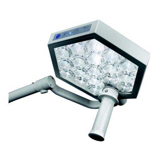
The technology of the lighting system The light head The light head is ergonomically adjusted via the non-sterile control panel on the light Operation head. The light intensity can be set in the range from 30 % to 100 %. A reduction (dimming) Light intensity of the light intensity does not change the colour temperature of the light. -
Page 21: Identification Of The Lighting System
Identification of the lighting system Use of serial numbers and Figure 1 device labels TRUMPF Medizin Systeme GmbH + Co. KG Carl-Zeiss-Straße 7-9 07318 Saalfeld A light system is identified by its device label Made in Germany TruLight 1000 / ceiling and serial numbers. -
Page 22: Markings On The Mobile Stand Version
Identification of the lighting system Figure 2 4.1.3 Markings on the mobile stand version C: Mobile stand version • Device label ① with the main serial number on the cover of the power supply unit. • Serial numbers ② of the individual components are provided at: –... -
Page 23: Description Of Devices And Functions
Description of devices and functions Description of the ceiling- Figure 3 mounted version Components of the ceiling-mounted version The ceiling mounted version consists of: • A single arm support arm system with a light head ③ on the quarter bracket ⑤. •... -
Page 24: Functional Description Of The Support Arm System, Ceiling Version
Description of devices and functions Functional description of the Figure 4 support arm system, ceiling version Mobility of the support arm system The horizontally rotatable boom ⑥ together with the horizontal and vertically adjustable spring arm ④ facilitate stable posi oning of the light head ③... -
Page 25: Description Of The Wall-Mounted Version
Description of devices and functions Description of the wall- Figure 5 mounted version Components of the wall-mounted version The wall-mounted version consists of: • A two-arm support arm system with a light head ① on the quarter bracket ③. • The support arm system comprises: –... -
Page 26: Functional Description Of The Support Arm System, Wall-Mounted Version
Description of devices and functions Functional description of the Figure 6 support arm system, wall- mounted version Mobility of the support arm system The horizontally rotatable boom ⑦ together with the horizontal and vertically adjustable spring arm ② facilitate stable posi oning of the light head ①... -
Page 27: Description Of Mobile Stand Version
Description of devices and functions Description of mobile stand Figure 7 version Components of the mobile stand version The mobile stand version consists of: • A single arm support arm system with a light head ⑤ on the quarter bracket ⑦. •... -
Page 28: Functional Description Of The Support Arm System, Mobile Stand Version
Description of devices and functions Functional description of the Figure 8 support arm system, mobile stand version Mobility of the support arm system The stand base with castors ⑤ facilitates unrestricted mobility. The horizontally and ver cally adjustable spring arm ⑧ on the stand rod ⑨... -
Page 29: Commissioning
Commissioning Checking the lighting system Figure 9 For all versions of the lighting system, a function test and a visual inspection should be carried out before use, or at least once per week. WARNING Contamination and infection hazard for patients Loose or damaged parts may fall into wounds. -
Page 30: Danger Of Pinching When Positioning The Lighting System
Commissioning connected to the support arm systems of the lighting system. 6.1.1 Danger of pinching when positioning the Figure 10 lighting system The positioning function of the lighting system is safe to operate. Pinching injuries during positioning may nevertheless occur. ... -
Page 31: Positioning The Cover-Mounted/Wall-Mounted Version
Commissioning Figure 11 6.1.3 Positioning the cover-mounted / wall- mounted version With the ceiling-mounted and wall-mounted version, the best mobility of the support arm is achieved in a “V-type arrangement”. Working distance Using the sterilisable handle, position the light head at a working distance of 70 –... -
Page 32: Power Supply Of Wall-Mounted Version Cable Connection
Commissioning Figure 12 6.1.4 Power supply of wall-mounted version cable connection The power supply of the wall-mounted version with cable connec on is established by a mains cable ③ with a cold- device plug and a shockproof plug. WARNING Electric shock There is a risk of electric shock in the event of contact with damaged... -
Page 33: Positioning The Mobile Stand Version
Commissioning Figure 13 6.1.5 Positioning the mobile stand version The mobile stand version has a high tilting stability. The following, basic precautions must nevertheless be considered when positioning the mobile stand version. ATTENTION Tilting of the stand The tilting stability of the mobile stand version can be at risk due to objects lying on the floor, uneven floors or the mains cable ④: •... -
Page 34: Power Supply Of The Mobile Stand Version
Commissioning Figure 14 6.1.6 Power supply of the mobile stand version The power supply of the mobile stand version is established by a mains cable ④ with cold-device plug and a safety connector. WARNING Electric shock There is a risk of electric shock in the event of contact with damaged electrical components: •... -
Page 35: Operation
Operation Working rules The safety instructions must be read and adhered to when using the lighting system Compliance with safety instructions to ensure that it is safely handled and to prevent harm to the patient. Preparatory measures Measures that should be considered before using the lighting system. Checking the lighting system For all versions of the lighting system, a function test and a visual inspection should Visual inspection... -
Page 36: Measures To Take When Using The Lighting System
Operation Examinations in the field of vision WARNING Damage to vision In case of examinations in the field of vision of the patient, the high intensity of illumination by the light heads may cause damage to vision: • Protect the patient's eyes, e.g. with protective glasses. •... -
Page 37: Attaching / Removing The Sterilisable Handle
Operation Attaching / removing the sterilisable Figure 15 handle The sterilisable handle ④ is fixed to the handle adapter ① with a ball latch ②. WARNING Contamination and infection hazard for patients Check the handle for damage to the material, cracks or deformations. -
Page 38: Switching The Light Head On / Off
Operation Switching the light head on / off Figure 16 The ceiling-mounted version of the lighting system is connected to the power supply via a fixed connection. Establishing the voltage supply Ceiling and wall-mounted version with fixed connection: • Switch on the master switch in the examination room. Wall-mounted version and mobile stand version with cable connection: •... -
Page 39: Cleaning And Disinfection
Cleaning and disinfection Regular cleaning and disinfection with suitable cleaning or disinfection agents is necessary for the safe use of the surgical light. WARNING Electric shock Touching live components may result in an electric shock. • Disconnect the device before cleaning and disinfection: •... -
Page 40: Cleaning And Disinfection
Cleaning and disinfection Cleaning and disinfection 8.1.1 General Cleaning and disinfection of the surgical lights may only be performed by a hygiene Performed by hygiene specialist staff specialist or a person instructed by the hygiene specialist. For cleaning and disinfection you should only use agents and chemicals tested by and Only use recommended cleaning agents approved by Trumpf Medical with regard to their material compatibility in and disinfectants... -
Page 41: Recommended Disinfectants
Cleaning and disinfection 3. Moisten a cloth with a drop of cleaning or disinfecting agent. Clean the surgical light with the damp but not wet cloth. WARNING Risk of fire or explosion with disinfectants Production of gases, fumes or mists when using disinfectants may create a combustible or explosive atmosphere. -
Page 42: Sterilisation
Sterilisation The handles are made of heat- and impact-resistant polyphenylene sulphone (PPSU) Material plastic. NOTE Warranty claim Failure to comply with the sterilisation requirements will render any warranty claim null and void. --------------------------------------------------------------------------------------- No warranty is accepted for damage, which is due to the use of unsuitable sterilisation methods. -
Page 43: Sterilising Handles For Examination Lights
Sterilisation 6. Check the cover pane (where present) for firm attachment and exchange the handle as required. An automatic method using a machine (disinfector) should be used for cleaning / disinfection in accordance with DIN EN ISO 15883-1. The effectiveness of the method used must be generally accepted (e.g. -
Page 44: Cleaning And Disinfection
Sterilisation 9.3.2 Cleaning and disinfection NOTE Sterilisation faults lead to product damage Product damage may result when the specifications and instructions provided below are not considered or adhered to. Furthermore, it would render any claim for damages void! • Do not use dry-heat sterilisation for sterilisable handles. Cleaning The sterilisable handles may be cleaned with mildly alkali cleaners without active chlorine. -
Page 45: Sterilisation Packaging
Sterilisation WARNING Contamination and infection hazard for patients Check handles after sterilisation for material damage, cracks or deformation, as detaching material particles may fall into the wounds. • Handles that are damaged, have undergone a maximum of 350 steam sterilisation cycles or are older than 1.5 years must be immediately exchanged. -
Page 46: Inspections, Maintenance And Repairs
Inspections, maintenance and repairs All devices are subject to wear and tear over time. The safety and function of the device must therefore be inspected after regular inspection and maintenance intervals. Repeat inspections must be carried out according to the specific national regulations. -
Page 47: Repairs
1 0 Inspections, maintenance and repairs • Rotation of the support arms, adjustment of the stops; adjust as necessary; • ease of movement of the joints; adjust as necessary; • position of the height stops; adjust as necessary; • attachment of the securing elements, grease as necessary; •... -
Page 48: Adjustments
Adjustments 11.1 Specifications Figure 17 Adjustment work may only be performed by specialised technical staff of the operating company following appropriate hospital technician training by Trumpf Medical. 11.2 Adjusting the spring force on the spring The weight of the light head is compensated by a spring which is installed in the spring arm ①. -
Page 49: Adjusting The Brake Force Of The Quarter Bracket
1 1 Adjustments 11.3 Adjusting the brake force of the quarter Figure 18 bracket If the light head does not remain stable in the vertical rotation position, the braking force for the rotation of the light head must be readjusted on the joint between the spring arm ① and the quarter bracket ②. -
Page 50: Wearing Parts
Wearing parts Wearing parts may only be exchanged by specialised technical staff of the operating company following appropriate hospital technician training by Trumpf Medical. Handles and brake screws High-wear part Chapter Sterilisable handle for light head; plastic see Chapter 7.4 0337642 (pack of 3) Brake screw with slot on the quarter... -
Page 51: Troubleshooting
Troubleshooting NOTE Recurrent faults If a fault recurs or cannot be remedied, put the device out of service and contact the technical customer service. Causes of faults and fault removal Error Possible cause Remedy Chapter Suspension / mobility Light head drops / rises Spring force in spring arm is Adjusting the spring force see Chapter 11.1... -
Page 52: Technical Data
Technical data 14.1 Device data Electrical data Designation Electrical data Connected voltage at the power supply unit 100 V AC - 240 V AC, 50 / 60 Hz Max. power uptake of whole system 50 VA Nominal frequency 50 / 60 Hz Output current with 24 V secondary voltage <1.25 A Internal fuse (mobile stand version only) -
Page 53: Emc Information
1 4 Technical data 14.2 EMC information EMC notes WARNING Operate the device only with the stated accessories. TruLight™1000 may only be operated with the accessories stated in the accompanying documents. Operation with accessories, converters or conduits other than those stated in the accompanying documents can lead to increased EMC emissions or reduced interference immunity of the device and thus to improper use. - Page 54 1 4 Technical data Guidelines and manufacturer's declaration - electromagnetic immunity NOTE Avoid environments with electromagnetic fields and interference above the given levels Guidelines and manufacturer's declaration - ELECTROMAGNETIC IMMUNITY TruLight™ 1000 is intended for use in the ELECTROMAGNETIC ENVIRONMENT described below. The customer or user should ensure that the TruLight™...
- Page 55 1 4 Technical data Guidelines and manufacturer declaration - immunity to electromagnetic interference / portable and mobile radio devices Portable and mobile RF communication devices should be used no closer to any part of the TruLight™ 1000, including cables, than the recommended separation distance calculated from the equation applicable to the frequency of the transmitter. NOTE TruLight™...
- Page 56 1 4 Technical data Immunity level of RF fields from wireless communication device Table: Special frequencies Test Band Service Modulation max. Distance Immunity Frequency (MHz) power (W) level (V/m) (MHz) 380 – 390 TETRA 400 Pulse modulation 18 Hz 430 – 470 GMRS 460 Pulse modulation FM ±5 FRS 460...
- Page 57 1 4 Technical data Controlled RF interference variables Recommended separation distances between portable and mobile RF communication equipment and TruLight™ 1000 TruLight™ 1000 is intended for use in an ELECTROMAGNETIC ENVIRONMENT where the radiated RF disturbances are monitored. The customer or user can help to prevent electromagnetic interference by maintaining the minimum distances between the portable and mobile RF telecommunication equipment (transmitters) and TruLight™...
- Page 58 TRUMPF Medizin Systeme GmbH + Co. KG Carl-Zeiss-Straße 7-9 D-07318 Saalfeld Telefon: +49 3671 586-0 Telefax: +49 3671 586-41165 E-Mail: info@trumpfmedical.com www.trumpfmedical.com...
Need help?
Do you have a question about the Trumpf Medical TruLight 1000 and is the answer not in the manual?
Questions and answers