Table of Contents
Advertisement
Quick Links
DS7 - Dual Head Distant Yellow / Green Digital DCC Signal
HANDLE WITH CARE - THIS MODEL IS NOT A TOY AND IS FRAGILE!
This signal incorporates a DCC decoder to enable it to be plugged or wired directly into the track and be controlled by any controller which
is able to control DCC accessories. Please read these instructions before fitting your signal.
1
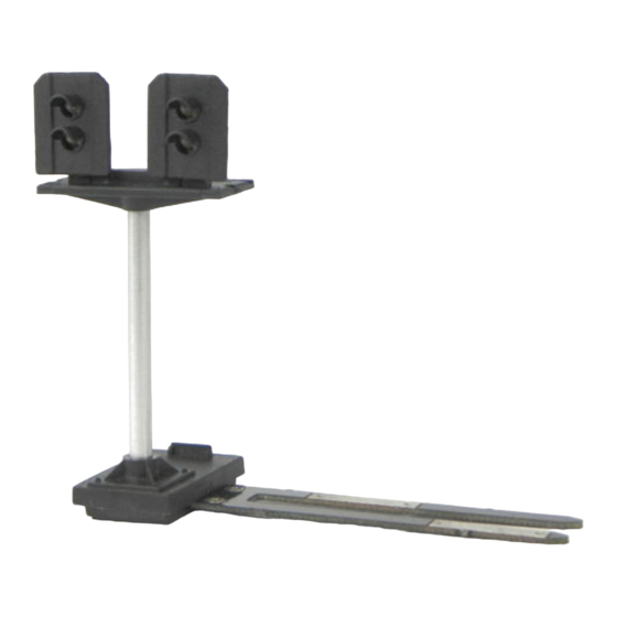
FITTING YOUR SIGNAL
•
Switch off your DCC controller and
power to your Track before fitting signal!
• Locate the power clip slots in the track* and
holding the signal BASE only, carefully align
and push the signal contact fingers into slots.
This may be a tight fit so take great care!
• Switch on controller and power to the track -
the Signal will light.
If the signal does not light at this stage see
ʻTroubleshootingʼ below before going further
Carefully Push
contact fingers in
between the
Power clip slots
!
Always hold signal by base,
never by the post or head!
* Wiring to non Hornby or Bachmann fixed Tracks
These signals can only clip
directly into standard Hornby or
Bachmann tracks which have
slots for a power clip. If you do not
have this type of track or want to
position your signal in a different
place you can carefully cut off
contact fingers where shown and
connect wires from the 2 contacts
marked X to the nearest DCC track - it does not matter
which way round the wires are connected.
(NB Peco Streamline flexible track does have deep
slots which can work by using packing under fingers)
Troubleshooting
Step 2 is the ʻOne Touchʼ DCC stage which programs the
accessory address into the signal. If it does not work:
• Check that one of the signal LEDs is lit - if not and
locos etc run correctly on the same piece of track check
the signal contact fingers are clean and tightly fitted
between the track sleeper and rail - clean if necessary.
• If a Signal LED is lit double check that your DCC
controller is in accessory addressing mode - note that
this is completely different to Locomotive addresses and
will be explained in your controller instructions.
• Try fitting the signal to another section of track (or use
pieces of wire to temporarily connect it to another track)
• If these steps fail contact your dealer or DCP support.
Adding extra detail
The signal is supplied with a sprue of plastic parts for
you to add extra detail like ladder, handrails, phone and
location board if you wish. These may be cut from the
sprue with small cutters or a knife and fixed in place
using standard model glue such as Liquid poly, etc.
You can use the Location board to show the DCC
address of the signal by cutting out and sticking a
number from the table printed overleaf. You can also
weather or paint the signal and add scatter material etc
around the base and fingers, though take care not to
cover the Learn or finger contacts and never let water
or moisture get into the base of the signal as this
contains sensitive electronics.
This signal is our design and based on colour light
signals in North Norfolk. As well as a range of Digital
signals you can also buy various kits of this signal in 2,
3 or 4 aspect single and dual head designs.
2
SETTING THE SIGNAL ADDRESS
•
You need to choose 2 DCC addresses for your
Dual signal, one for left and one for right head:
We will use address 75 for left and 80 for right.
• Set up your controller to control DCC
accessories (refer to controllers instructions)
then set your controller to the address you
choose for the left signal head (eg 75).
•
To program the signal, use a short link of
•
insulated wire to briefly touch together the
ʻLearnʼ contacts until the left head lights flash,
then send the or ʻdirectionʼ command from
your controller that you want to signal green.
The left head will stop flashing, light up green
and is now programmed to that address (75).
To program the other head, set your controller
•
to the address you want to give the right head
(eg 80), touch the learn contacts and the left
head will flash, then touch them again and the
right head will flash. Again send the or
Power
command from your controller you want to
clip slots
signal green - the right head will stop flashing,
light green and is set to the other address (80).
ʻLearnʼ Contacts
Touch together contacts under
base to program Signal address
Synchronising with other Signals and Points
Although each signal can have its own unique address, if
you wish you can easily synchronise some of your
signals and/or points to work together to add basic
automation to your layout which can also make it easier
x
to run and more realistic.
For example you may wish to sync a Home and Distant
x
signal together so that the Distant signal automatically
changes with the Home signal before it. To do this you
simply program both signals with the same DCC address
which you can do either by touching the contacts on both
signals then programming them at the same time, or
doing each individually with the same address.
Note that a Train-Tech Digital signal always goes to
Green immediately after programming, making it easier
to synchronise multiple signals as all signals have green.
Similarly you could sync a Signal to a Point controlled by
a Train-Tech DCC Point controller so that the signal is
always red when the point is against it and green when it
is clear to go. Again you can do this by programming the
Point and Signal with the same DCC address.
Computer Control
Some DCC controllers can be connected to a PC to
enable computer control of locomotives and accessories
like this signal - for more details on what is compatible
with your system consult your controller supplier.
Location board labels
These legends can be cut out and glued to the
model Location board on the plastic detailing
sprue. You could use the DCC address you have
programmed into your signal which will make the
signal easier to identify and operate.
1
2
11 12 13 14 15 16 17 18 19 20
21 22 23 24 25 26 27 28 29 30
31 32 33 34 35 36 37 38 39 40
41 42 43 44 45 46 47 48 49 50
51 52 53 54 55 56 57 58 59 60
61 62 63 64 65 66 67 68 69 70
71 72 73 74 75 76 77 78 79 80
81 82 83 84 85 86 87 88 89 90
91 92 93 94 95 96 97 98 99 100
AD CA DA ES EN GE GY MY PN NW
ABCDEFGHIJKLMNOPQRSTUVWXYZ
ABCDEFGHIJKLMNOPQRSTUVWXYZ
3
4
5
6
7
8
9 10
3
CONTROLLING YOUR SIGNAL
•
You control the signal by setting your controller
to the DCC accessory address of your signal
and sending a or ʻdirectionʼ command from
your controller to change the Signal colour
(actual terms used for accessory control vary
between controllers so refer to the instructions)
Address (75) or = Left Yellow or Green
Address (80) or = Right Yellow or Green
Each signal head can have their own unique
address or can be synchronised to other DCC
signals or points etc by giving them the same
address as each other. Your signal will retain
your chosen address unless you change it,
which you can do by following step 2.
Extra Details can also be
fitted - see below
Tip: The Location board can
be used to show the DCC
address of your signal to
make it easier to identify -
you can cut out and glue the
address from the table
printed below
Extra details
The signal is supplied with a kit of plastic parts for you
to add extra details like ladder, handrails, phone and
location board if you wish. These may be cut from the
supports using small cutters or a knife on a cutting mat,
but take care as these parts are extremely small and
fragile, so we recommend using the following technique
to remove them without damage.
We suggest you first remove ladder and main parts by
carefully cutting the thicker supports first - after cutting
these they should break away from the other parts by
gently ʻrockingʼ and you can then trim the fine supports.
Parts may be cut from the supports using a knife on a
cutting mat or by using precision cutters which can be
invaluable for modellers - they are available from model
shops or direct from us at www.dcpexpress.com
You will also find that fine nose pliers or tweezers are
useful both for cutting out and fitting parts.
Parts can be glued in place using model adhesives
such as Liquid poly or cynoacrylate ʻsuperglueʼ etc.
We recommend first cutting the thicker supports to
release main parts then trimming off the small supports
You can use the Location board (small square sign) to
show the DCC address of the signal by cutting out and
glueing the number from the table printed.
You can also weather or paint the signal and add
scatter material or ballast etc around the base and
fingers, but take care not to cover the Learn or contact
fingers and never let water or moisture get into base of
the signal as this contains sensitive electronics.
Caution
This product is not a toy but a precision moulded
model kit and as such has small parts which may
choke or harm a child. Always take care when using
tools, electricity, adhesives and paints, especially when
children or pets are nearby.
Document Ref D779650/3
Advertisement
Table of Contents

Related Manuals for Train-Tech DS7


Summary of Contents for Train-Tech DS7
- Page 1 DS7 - Dual Head Distant Yellow / Green Digital DCC Signal HANDLE WITH CARE - THIS MODEL IS NOT A TOY AND IS FRAGILE! This signal incorporates a DCC decoder to enable it to be plugged or wired directly into the track and be controlled by any controller which is able to control DCC accessories.
- Page 2 SK8 Dual head Distant 2 aspect with LEDs • On DC one light is on & varies with speed SEE WWW.TRAIN-TECH.COM OR CONTACT DCP FOR FREE COLOUR BROCHURE • Helps bring your layout to life! BL1 OO/HO gauge Buffer Light...
Need help?
Do you have a question about the DS7 and is the answer not in the manual?
Questions and answers