Table of Contents
Advertisement
Quick Links
SAGE THERMAL GAS MASS FLOW METER
Operations and
Instruction Manual
For SAGE RIO Models SIX and SRX
ATEX Certified for Hazardous Service
DOCUMENT NUMBER 100-0162
REVISION 10 - SIX/SRX (SAGE RIO)
Make the Wise Choice.
Choose Sage Flow Meters.
SAGE METERING, INC.
8 Harris Court, D1
Monterey, CA 93940
1-866-677-SAGE (7243)
Tel 831-242-2030
Fax 831-655-4965
www.sagemetering.com
Advertisement
Table of Contents

Subscribe to Our Youtube Channel
Related Manuals for Sage RIO SIX

Summary of Contents for Sage RIO SIX
- Page 1 SAGE THERMAL GAS MASS FLOW METER Operations and Instruction Manual For SAGE RIO Models SIX and SRX ATEX Certified for Hazardous Service DOCUMENT NUMBER 100-0162 REVISION 10 - SIX/SRX (SAGE RIO) Make the Wise Choice. Choose Sage Flow Meters. SAGE METERING, INC.
-
Page 3: Table Of Contents
Sage Rio Organic (OLED) Display........ - Page 4 Returning Your Sage Flow Meter ........
-
Page 5: Welcome
115/230 VAC). The power dissipation is under 2.5 watts (e.g. under 100 ma at 24 VDC for the DC version.) Please let us know if we can assist you in any way with your Sage Meter, or if you have any questions about its installation, operation, or features. Simply phone us at 866-677-SAGE (7243), or visit our website at www.sagemetering.com to contact a... - Page 7 Section GETTING STARTED...
-
Page 9: Unpacking Your Sage Meter
A soft brush can be used to gently clean the sensing element’s surface, using Your Sage flow meter is a sensitive, yet rugged, caution to avoid damaging the sensor elements precision built electronic instrument. Upon delivery, (the RTDs). -
Page 10: Installation And Mounting
field. However, on both the Transmitter as well as the Remote if the displ y needs to be rotated, then the meter must be sent back to Sage to be modified. Do not Electronics enclosure. Do not mismatch the seri- attempt this in the field. -
Page 11: Insertion Flow Meter Application
GUIDELINE DRAWING (page 14) and INSTALLA- pressure during installation, a hot tap drill (not TION DEPTH CHART (page 15). available through Sage Metering) may be required. SAGE VALVE ASSEMBLY OPERATION FLOW CONDITIONING AND STRAIGHT RUN Valve assemblies (SVA05 and SVA05LP) are an op -... -
Page 12: Compression Fitting Operation
2. Make sure that the tubing is positioned properly can be provided by the user or purchased as an per the PROBE INSERTION GUIDELINE DRAW- option from Sage Metering (see page 38). Prior to ING AND CHART, pages 14 & 15. installation, a clearance hole to accommodate the 3. -
Page 13: Captive Flow Conditioners
Flow Conditioning Assembly is inserted here. NOTE: The larger of the two perforated plates of the Sage conditioning basket is positioned between two flanges and two gaskets as shown. The smaller of the two perforated plates of the conditioner will freely slide into the application pipe, facing downstream. -
Page 14: Probe Insertion Guideline Drawing
Flow Conditioners (page 13) are in stalled (con- The center of the pipe (assuming a well developed tact Sage for assistance if needed). Refer to page 13 to turbulent flow profile) is fairly flat, and easy to see the benefits of incorporating Flow Conditioners. -
Page 15: Installation Depth Chart
OD. 1 For other Pipe Schedules, such as Schedule 10, contact Sage, however the Y dimension will be the same for any Schedule Pipe 2 The 1" Pipe Size needs to have the Probe “Bottomed Out” (option “BOT"); the calibration method for the 1 ⁄... -
Page 16: Configuration For Utilizing Four Flow Meters For Large Round Pipes
O p e r a t i o n s a n d I n s t r u c t i o n M a n u a l CONFIGURATION FOR UTILIZING FOUR (4) SAGE INSERTION MASS FLOW METERS FOR LARGE ROUND PIPES OR DUCTS LARGER THAN 36"... -
Page 17: In-Line Flow Meter Application
IN-LINE FLOW METERS ing, flanging, welding, etc. DO NOT USE REDUCERS. It includes the sensing element (a self-heated flow In-line mounting styles are available through Sage sensor and a temperature/reference sensor) mounted Metering, Inc. in sizes from 1/4" pipe through 4"... -
Page 18: Terminal Hookup Rio Integral (Series Six)
S A G E M E T E R I N G , I N C . O p e r a t i o n s a n d I n s t r u c t i o n M a n u a l Rio Integral (Series SIX) SEE “WIRING”... -
Page 19: Vdc Rio Integral Terminals Series Six
4 Pulse width 250 msec default (adjustable with Addresser software) 10 Modbus Ground becomes isolated from the B6 Power Supply Ground only on Rio PLUS version 5 Using HART or Sage Addresser, a Low Flow Cutoff (LFC), commonly referred to as Min Cutoff or Zero (specify “PLUS”) -
Page 20: Integral Terminals (Series Six)
4 Pulse width 250 msec default (adjustable with Addresser software) 10 Modbus Ground becomes isolated from the B6 Power Supply Ground only on Rio PLUS version 5 Using HART or Sage Addresser, a Low Flow Cutoff (LFC), commonly referred to as Min Cutoff or Zero (specify “PLUS”) -
Page 21: Terminal Hookup Rio Remote (Series Srx)
O p e r a t i o n s a n d I n s t r u c t i o n M a n u a l S A G E M E T E R I N G , I N C . Rio Remote (Series SRX) SEE “WIRING”... -
Page 22: Vdc Rio Remote Terminals (Series Srx)
4 Pulse width 250 msec default (adjustable with Addresser software) 10 Modbus Ground becomes isolated from the B6 Power Supply Ground only on Rio PLUS version 5 Using HART or Sage Addresser, a Low Flow Cutoff (LFC), commonly referred to as Min Cutoff or Zero (specify “PLUS”) -
Page 23: Ac Powered Rio And Dc Powered Rio Plus Remote Series Terminals (Series Srx)
4 Pulse width 250 msec default (adjustable with Addresser software) 10 Modbus Ground becomes isolated from the B6 Power Supply Ground only on Rio PLUS version 5 Using HART or Sage Addresser, a Low Flow Cutoff (LFC), commonly referred to as Min Cutoff or Zero (specify “PLUS”) -
Page 24: Junction Box Wiring Terminals For Remote Style Meters
Green wires, and also short together the Black and Orange wires. These extra wires are part of 3 Sage supplies 25 feet of cable for bench testing only. User is responsible to provide ATEX approved the meter's Lead Length Compensation circuitry, allowing the user to change the length of the inter- cable for final installation. -
Page 25: Section B
Section STYLES AND FEATURES... -
Page 27: Principle Of Operation
fluctua- (RTDs). The two RTDs are clad in a protective 316SS tions in gas temperature. It is the “job” of the Sage or Hastelloy C sheath and are driven by a proprietary proprietary sensor drive circuit to maintain the sensor drive circuit. -
Page 28: Features And Benefits
SAGE RIO THERMAL MASS FLOW METER FOR GASES Direct Mass Flow – No need for separate temperature or pressure The Sage Rio Thermal Mass Flow Meter provides the same levels of transmitters performance found in the popular Sage Prime with the added ATEX High Accuracy and Repeatability –... -
Page 29: Sage Rio Styles & Specifications
S A G E M E T E R I N G , I N C . Sage Rio Styles and Specifications SAGE METERING is a manufacturer of high performance Thermal Mass Flow Meters and furnaces. Environmental reporting of Greenhouse Gases from combustion which measure the flow rate and consumption of gases for multiple industrial appli-... -
Page 30: Sage Rio Organic (Oled) Display
S A G E M E T E R I N G , I N C . O p e r a t i o n s a n d I n s t r u c t i o n M a n u a l Sage Rio Organic (OLED) Display 1,2,3 Raw Calibration milliwatts (mw) for Diagnostics and Periodic “Zero Flow”... -
Page 31: Hazardous Location Approvals
• Customer repair of the product (or replacement HAZARDOUS LOCATION APPROVALS of components) is not allowed. Sage Rio Gas Flow Meter Type SIX or SRX are ATEX approved. • If the equipment is used in a manner not specified by the manufacturer, the protection provided by Certification No.: TÜV 12 ATEX 7167 X... -
Page 32: Declaration Of Conformity Certificate
S A G E M E T E R I N G , I N C . O p e r a t i o n s a n d I n s t r u c t i o n M a n u a l REV. -
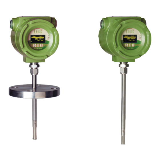
Page 33: Six Series Integral Style Flow Meters
O p e r a t i o n s a n d I n s t r u c t i o n M a n u a l S A G E M E T E R I N G , I N C . SIX Series Integral Style Mass Flow Meters IN-LINE STYLE 150#, 300#, or 600# flanged ends are optionally available. -
Page 34: Srx Series Remote Style Flow Meters
S A G E M E T E R I N G , I N C . O p e r a t i o n s a n d I n s t r u c t i o n M a n u a l SRX Series Remote Style Mass Flow Meters 1, 3 IN-LINE STYLE... -
Page 35: Remote Bracket Layout
O p e r a t i o n s a n d I n s t r u c t i o n M a n u a l S A G E M E T E R I N G , I N C . Sage Rio Remote Bracket Layout 3/4" NPT... -
Page 36: Mounting Hardware
(of appropriate radius) to mate with existing pipe after a 3/4" hole has been drilled in pipe. The 3/4" 24" 20.25" 3/4"x1" Male Coupling of the Sage Isolation Valve Assembly HALF COUPLING will thread into the user’s 3/4" threadolet. (THREADOLET) STCF SERIES TEFLON FERRULE... -
Page 37: Sva05Lp Low Pressure Isolation Valve Assembly
• Assumes ⁄ " Insertion Probe inserted to center of a Pipe (see Sage Probe Insertion Guidelines) • Teflon Ferrule permits ease of Probe insertion or removal • Exercise caution when loosening Ferrule nut during insertion and removal of Probe, since this model has no Safety Chain •... -
Page 38: In-Line And Insertion Flanges
S A G E M E T E R I N G , I N C . O p e r a t i o n s a n d I n s t r u c t i o n M a n u a l Flanged Ends for Flanged Mounting for In-Line Meter... -
Page 39: Section D
Section DIAGNOSTICS... -
Page 41: Common Diagnostics
VFDs. c) Note, in late 2009, the Sage Rio was modified to incorporate a built-in photocell. The purpose SYMPTOM: Meter reading zero continuously, or Full... - Page 42 flow body or if valve is too close upstream n) Meter may appear to be reading high if user is to meter. comparing Sage flow meter readings (SCFM) to c) Not following Probe Insertion Guideline. an uncorrected volumetric device (ACFM). For example, at constant volume, a decrease in gas d) If sensor is inserted in reverse (“Upstream”...
- Page 43 Serial Number Tag has identical Serial Numbers to Tag on Remote Enclosure. i) Meter may appear to be reading low if user is comparing Sage flow meter readings (SCFM) to an uncorrected volumetric device (ACFM). For example, at constant volume, an increase in gas temperature will lower the mass flow (SCFM).
-
Page 44: In-Situ Calibration Check
(EB61 Report, Annex 11, Page 1). 3 Sage "zeros" the meter in a horizontal pipe. If you have a vertical pipe, mW will be slightly lower 4. A value greater than 5 mw, but less than or equal at zero (also see note 4). -
Page 45: Section E
Section WARRANTIES AND SERVICE WORK... -
Page 47: Limited Warranty
Sage at our factory in Monterey, California, prove 1) If credit card order or non-credit card order is to be defective. Sage shall not be liable for installa- cancelled within 7 days of issuance of purchase tion charges, for expenses of Buyer for repairs or... - Page 48 1 month of ship- ment, unless authorized by a representative at Sage Metering, Inc. The Sage representative will issue a Return Material Authorization (RMA) at that time and will advise of the restocking fee.
-
Page 49: Returning Your Sage Flow Meter
Metering. This decontamination includes the sen- Monday through Friday. sor, probe, electronics and enclosures internally A Sage RMA Form (see page 52) must be filled out and externally. All packaging must be clean and and included with the meter being returned to free from contamination. -
Page 50: Return Material Authorization Form
(All non-warranty repairs could be subject to a minimum evaluation charge) Recommended steps to be used to duplicate problem/symptoms Sage Metering Technical Contact Take special care when packaging your meter for return to the factory. The sensor in particular may easily be damaged if not prevented from shifting around within the package and if the sensor itself is not cov- ered to keep it from contacting other package contents. -
Page 51: Section F
Section MODBUS... -
Page 53: Modbus Register Listing
O p e r a t i o n s a n d I n s t r u c t i o n M a n u a l S A G E M E T E R I N G , I N C . Modbus Register Listing UINT32 IEEE Float... -
Page 54: Modbus Modbus Protocol & Function Codes
The third field contains the data and byte counts. The fourth field contains the CRC value. 1 Parity on the Wireless Devices manufactured by Obvius is “None” rather than “Even”. The Sage default is 19200-8-E-1. Change to 19200-8-N-1 for the Obvius Modhoppers and related wireless devices. - Page 55 CT is the register count needed to transfer data. Typically this byte is set to 02 to request 1 full IEEE754 floating point value. (Modbus single registers are 16 bits wide, Sage floating point values are 32 bits wide.) DATA0-DATAn are bytes in binary format returned from the slave device representing the contents of the selected register(s).
- Page 56 16 (0x10) WRITE REGISTERS Writes the binary contents of the specified register into the meter. Sage Rio values are typically 32 bits wide (4 bytes) and contain a single IEEE754 floating point value. Modbus registers are 16 bits wide (2 bytes) so a minimum of 2 Modbus registers are required to transfer all floating point bits into the...
- Page 57 ASCII Text – SAGE Rio v1.81x Response The Sage Rio will respond with an echo of the slave address and function code. The byte count will be 19 (0x13) to allow the master to account for all the remaining bytes that follow.
- Page 58 1 uLONG actual displayed total *NOTE: Sage Rio Meters are factory programmed with the MODBUS slave address = 48 (0x30). It may be extremely useful to be able to write to an unknown slave address with a simple broadcast command. Be sure only one Sage Rio is connected during any broadcast writes using slave address = 0.
-
Page 59: Sage Register Output Format
READ/WRITE Program with drop-down menus for convenient user interface between your PC or laptop registers will require significant translation.) and the Modbus Terminals of the Sage Rio. Con tact IEEE754 FLOATING POINT Sage for ordering information and instructions. Computer systems hosting a MODBUS network typi- SAGE ADDRESSER TECHNICAL ASSISTANCE cally store single precision floating point data in the... -
Page 60: Sage Addresser Typical Printout (Version 3.14)
S A G E M E T E R I N G , I N C . O p e r a t i o n s a n d I n s t r u c t i o n M a n u a l Sage Addresser Typical Printout (Version 3.14) Units: SCFM Modbus: 0x31 Copyright 2012, Sage Metering Inc. -
Page 61: Section G
Section HART... - Page 63 HART communications are optionally provided on NOTE: HART will only be available if the 4-20 mA some versions of the Sage Prime Thermal Mass Flow output is externally powered. A minimum resistance Meter. HART is designated by the code “HART” in of 250 ohms is required between the power supply the model number.
-
Page 64: Hart Wiring Instructions
S A G E M E T E R I N G , I N C . O p e r a t i o n s a n d I n s t r u c t i o n M a n u a l HART Wiring Instructions DC INPUT POWER WIRING INPUT POWER SUPPLY... -
Page 65: Ac Input Power Wiring
O p e r a t i o n s a n d I n s t r u c t i o n M a n u a l S A G E M E T E R I N G , I N C . AC INPUT POWER WIRING AC POWER 115/230 VAC... -
Page 66: Hart Menu Tree
S A G E M E T E R I N G , I N C . O p e r a t i o n s a n d I n s t r u c t i o n M a n u a l HART Menu Tree 1 Flow Rate 1 PV Measurements... - Page 67 O p e r a t i o n s a n d I n s t r u c t i o n M a n u a l S A G E M E T E R I N G , I N C . 1 K Factor 2 PV Damping 3 DEVICE SETUP...
-
Page 68: Hart Details
S A G E M E T E R I N G , I N C . O p e r a t i o n s a n d I n s t r u c t i o n M a n u a l HART Following reviews the various parameters used in the K Factor [Fast Key 1,1,2,5]... - Page 69 Enter the Upper Range Value for the Primary Variable (flow rate). The URV must be in the identified units of measurement and must be within the calibration range of the instrument. Consult Sage Metering if assistance is requied. REV. 10-SIX/SRX...
- Page 70 S A G E M E T E R I N G , I N C . O p e r a t i o n s a n d I n s t r u c t i o n M a n u a l Totalizer Long Tag [Fast Key 3,3,2] Total Units [Fast Key 3,2,2,1]...
-
Page 71: Section H
Section APPENDIX... -
Page 73: Correction Factors For Varying Gas Mixes
Variation From Original Condensation May Develop Digester Gas Calibration Sage can calibrate for any Digester Gas, Bio Gas or Landfill Gas Mix. However, it may be helpful to have correction factors for a typical calibration, in the event that the composition changes after delivery. -
Page 74: J-Box And Upstream Orientation
S A G E M E T E R I N G , I N C . O p e r a t i o n s a n d I n s t r u c t i o n M a n u a l J-Box and Upstream Orientation NOTE: ATEX approved cable... -
Page 75: What Is A Thermal Mass Flow Meter
What is a Thermal Mass Flow Meter? • What is a Thermal Mass Flow Meter? It is a meter • The Sage proprietary sensor drive circuitry main- that directly measures the gas mass flow based tains a constant overheat between the flow sensor on the principle of conductive and convective and the reference sensor.
Need help?
Do you have a question about the RIO SIX and is the answer not in the manual?
Questions and answers