
Related Manuals for Victron energy Smart BatteryProtect 12/24V


Summary of Contents for Victron energy Smart BatteryProtect 12/24V
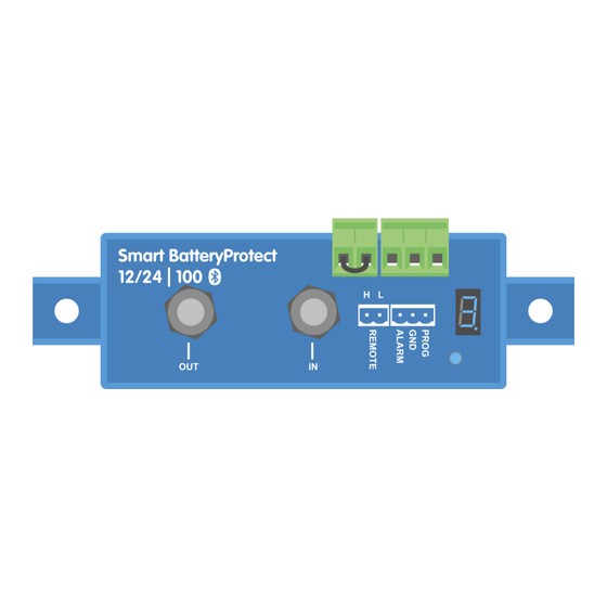
- Page 1 ENGLISH Smart BatteryProtect 12/24V 12/24V - 65A | 12/24V - 100A | 12/24V - 220A rev 00 08/2022...
-
Page 2: Table Of Contents
Smart BatteryProtect 12/24V Table of Contents 1. Introduction ........................... 1 2. Features ..........................2 3. Installation and wiring examples ....................3 3.1. Precautions and installation notes ..................3 3.2. Warning when connecting inverters and inverters/chargers ............4 3.3. Wiring examples ......................5 3.3.1. -
Page 3: Introduction
Smart BatteryProtect 12/24V 1. Introduction The Smart BatteryProtect disconnects the battery from non-essential loads before it is completely discharged (which would damage the battery) or before it has insufficient power left to crank the engine. It also provides an alternative to disable chargers without a remote on/off port to protect from over-voltage. -
Page 4: Features
Smart BatteryProtect 12/24V 2. Features The Smart BatteryProtect offers a wide range of different features. These include: • Protection of the battery against excessive discharge and can be used as a system on/off switch. • 12/24V auto ranging. The Smart BatteryProtect automatically detects system voltage one time only (can be re-triggered - see... -
Page 5: Installation And Wiring Examples
Smart BatteryProtect 12/24V 3. Installation and wiring examples 3.1. Precautions and installation notes There are a few basic things to keep in mind when installing a Smart BatteryProtect: 1. The Smart BatteryProtect must be installed in a well-ventilated area and preferably close (max 50 cm) to the battery (but, due to possible corrosive gasses not above the battery!). -
Page 6: Warning When Connecting Inverters And Inverters/Chargers
Smart BatteryProtect 12/24V 3.2. Warning when connecting inverters and inverters/chargers Under no circumstances is it permitted to connect inverters or inverter/chargers to a SBP via their DC inputs, a reverse current may flow that damages the SBP. In case you want to control an inverter or inverter/charger via a SBP, you must use the SBP to control the inverter or inverter/charger via its remote port. -
Page 7: Wiring Examples
Smart BatteryProtect 12/24V 3.3. Wiring examples This section contains various wiring examples to show all the possibilities of wiring. 3.3.1. Smart BatteryProtect in a simple system The example below shows a Smart BatteryProtect with the wire loop (default) between L and H of the remote terminal. When the wire loop is removed, the SBP disconnects the load after 90 seconds. -
Page 8: Smart Batteryprotect Remote On/Off Switch
Smart BatteryProtect 12/24V 3.3.2. Smart BatteryProtect remote on/off switch The below example shows a Smart BatteryProtect in a simple system with a remote on/off switch wired to the remote terminals. This switch can be used, for example, to turn the system remotely on and off. The power consumption of the Smart BatteryProtect... -
Page 9: Smart Batteryprotect In A Lithium System With External Bms And Load Disconnect Output
Smart BatteryProtect 12/24V 3.3.4. Smart BatteryProtect in a lithium system with external BMS and load disconnect output This wiring example shows a Smart BatteryProtect wired into a lithium system that is controlled by an external BMS (Victron smallBMS with pre-alarm). This BMS has a load and a charge disconnect output that can be wired directly to the Smart BatteryProtect H input of the remote terminal. -
Page 10: Two Smart Batteryprotects For Load And Charger Control
Smart BatteryProtect 12/24V 3.3.5. Two Smart BatteryProtects for load and charger control It is also possible to have several Smart BatteryProtect in one system, for example, to control chargers and loads at the same time. If the BMS signals a cell undervoltage, the SBP responsible for the load will disconnect the load from the battery to protect the battery from further discharge. -
Page 11: Operation And Programming
Smart BatteryProtect 12/24V 4. Operation and programming 4.1. Operation modes The Smart BatteryProtect has three operating modes, the appropriate mode can be selected via the VictronConnect app or a programming procedure (see chapter Programming [10]). • Mode A: Buzzer or LED mode (default). -
Page 12: Programming
• The battery positive must be connected to the IN terminal. Do not connect the OUT terminal yet. • The included ground wire must be connected to the battery minus and the GND terminal of the Smart BatteryProtect 12/24V. • The wire loop in the remote on/off terminal block must be removed. -
Page 13: Programming Table
Bluetooth can be disabled/re-enabled by selecting F (enable) or H (disable). Push button Push button wired to program the Smart BatteryProtect 4.2.3. Programming table Programming table for Smart BatteryProtect 12/24V 7-segment display Under voltage shutdown 12/24V system Under voltage restart 12/24V system 10.5V/21.0V... -
Page 14: Remote Control And Short Circuit Behavior
Smart BatteryProtect 12/24V 4.4. Remote control and short circuit behavior This section describes the behaviour of the Smart BatteryProtect when it is controlled via the remote on/off input and when a short circuit has been detected. • The Smart BatteryProtect will connect the load 1 second after the remote input is closed. -
Page 15: Compliance Statement
Smart BatteryProtect 12/24V 5. Compliance Statement Compliance statement (part 15.19) This device complies with part 15 of the FCC Rules. Operation is subject to the following two conditions: 1. this device may not cause harmful interference, and 2. this device must accept any interference received, including interference that may cause undesired operation. -
Page 16: Technical Specifications
Smart BatteryProtect 12/24V 6. Technical specifications 6.1. Technical specifications Smart BatteryProtect SBP-65 SBP-100 SBP-220 Max. continuous load current 100A 220A Peak current 250A 600A 600A Operating voltage range 6 - 35 V Current consumption BLE On and when on: 1.4mA When off or low voltage shutdown: 0.9mA BLE Off and when on: 1.2mA When off or low voltage shutdown: 0.7mA... -
Page 17: Appendix
Smart BatteryProtect 12/24V 7. Appendix 7.1. Error and Warning codes This appendix gives a list of error and warning codes and possible solutions. E0: Calibration failure Internal malfunction – calibration data failure/missing • Contact dealer for support – Fault is not user correctable and SBP requires replacement. - Page 18 Smart BatteryProtect 12/24V 3. Reconfigure the unit as required. E6: Reference voltage failure Internal malfunction - reference voltage failure/missing. • Contact dealer for support - Fault is not user correctable and SBP requires replacement. E7: BMS lockout BMS lockout protection is activated in the event the external BMS requests the SBP to consecutively disengage and then re-engage 3 times (typical behaviour during a shut down due to low cell voltage).
Need help?
Do you have a question about the Smart BatteryProtect 12/24V and is the answer not in the manual?
Questions and answers