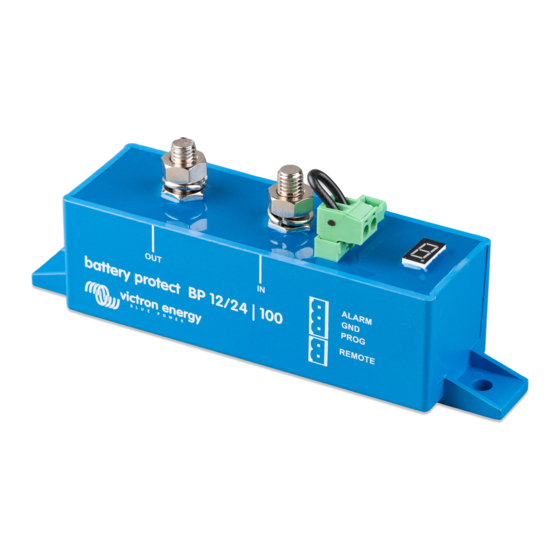
Summary of Contents for Victron energy BatteryProtect
- Page 1 ENGLISH BatteryProtect 12/24V 12/24V - 65A | 12/24V - 100A | 12/24V - 220A rev 04 - 11/2023 This manual is also available in HTML5.
-
Page 2: Table Of Contents
3.3.2. BatteryProtect remote on/off switch ................6 3.3.3. BatteryProtect in a lithium battery system with external BMS ..........6 3.3.4. BatteryProtect in a lithium system with external BMS and load disconnect output ......7 3.3.5. Two BatteryProtects for load and charger control ............. 8 3.3.6. -
Page 3: Introduction
Compared to the Smart BatteryProtect, the BatteryProtect must be programmed via the PROG pin to GND pin method. The BatteryProtect is a uni-directional device. It can only deal with current in one direction, so either current to a load, or current from a charger, but not both currents at the same time. -
Page 4: Features
The BatteryProtect offers a wide range of different features. These include: • Protection of the battery against excessive discharge and can be used as a system on/off switch. • 12/24V auto ranging. The BatteryProtect automatically detects system voltage one time only (can be re-triggered - see section Programming table [12]). -
Page 5: Installation And Wiring Examples
There are a few basic things to keep in mind when installing a BatteryProtect: 1. The BatteryProtect must be installed in a well-ventilated area and preferably close (max 50 cm) to the battery (but, due to possible corrosive gasses not above the battery!). -
Page 6: Warning When Connecting Inverters And Inverters/Chargers
BP. In case you want to control an inverter or inverter/charger via a BP, you must use the BP to control the inverter or inverter/charger via its remote port. See example below. Note that the image shown below is an example for all BatteryProtect models including the smart models. DC loads... -
Page 7: Wiring Examples
This section contains various wiring examples to show all the possibilities of wiring. 3.3.1. BatteryProtect in a simple system The example below shows a BatteryProtect with the wire loop (default) between the two-pin remote terminal. When the wire loop is removed, the BP disconnects the load after 90 seconds. -
Page 8: Batteryprotect Remote On/Off Switch
The below example shows a BatteryProtect in a simple system with a remote on/off switch wired to the remote terminals. This switch can be used, for example, to turn the system remotely on and off. The power consumption of the BatteryProtect is... -
Page 9: Batteryprotect In A Lithium System With External Bms And Load Disconnect Output
(Victron smallBMS with pre-alarm). This BMS has a load and a charge disconnect output that can be wired directly to the BatteryProtect pin labelled REMOTE of the remote terminal connector. As with the previous example, it is necessary to program the BP into Li-ion mode (see chapter Programming [11]). -
Page 10: Two Batteryprotects For Load And Charger Control
3.3.6. BatteryProtect Alarm output wiring The alarm output can be wired e.g. to an LED, a buzzer or a relay. For this, the BatteryProtect must be programmed in the respective mode because of slight differences in the behavior. See also the section Operation modes [10] for more details. - Page 11 BatteryProtect 12/24V Relay Buzzer DC loads Wiring an LED, Buzzer or Relay to the BatteryProtect output Page 9 Installation and wiring examples...
-
Page 12: Operation And Programming
BatteryProtect 12/24V 4. Operation and programming 4.1. Operation modes The BatteryProtect has three operating modes, the appropriate mode can be selected via a programming procedure (see chapter Programming [11] • Mode A: Buzzer or LED mode (default). • Mode B: Relay mode. -
Page 13: Programming
• The battery positive must be connected to the IN terminal. Do not connect the OUT terminal yet. • The included ground wire must be connected to the battery minus and the GND terminal of the BatteryProtect 12/24V. • The wire loop in the remote on/off terminal block must be removed. -
Page 14: Programming Table
BMS. This delay increases to 3 minutes in case of frequent switching. • In case of a short circuit, the BatteryProtect will attempt to connect the load every 5 seconds. After two attempts the display will show E1 (short circuit detected). -
Page 15: Technical Specifications
BatteryProtect 12/24V 5. Technical specifications 5.1. Technical specifications BatteryProtect BP-65 BP-100 BP-220 Max. continuous load current 100A 220A Peak current 250A 600A 600A Operating voltage range 6 - 35 V Current consumption When on: 1.5mA When off or low voltage shutdown: 0.6mA... -
Page 16: Appendix
BatteryProtect 12/24V 6. Appendix 6.1. Error and Warning codes This appendix gives a list of error and warning codes and possible solutions. E1: Short circuit Short circuit protection is activated in the event of a short circuit, an overload condition or excessive inrush current - such as when attempting to directly power an inverter or inverter/charger.


Need help?
Do you have a question about the BatteryProtect and is the answer not in the manual?
Questions and answers