Table of Contents
Advertisement
S S D D 1 1 7 7 5 5 H H V V D D C C / / D D C C C C o o n n v v e e r r t t e e r r U U s s e e r r
M M a a n n u u a a l l S S D D 1 1 7 7 5 5 H H V V - - U U E E N N - - V V e e r r 1 1 1 1 - -
2 2 0 0 2 2 2 2 0 0 3 3
SD175HV-UEN-Ver11-202203
SD175HV
D D C C / / D D C C C C o o n n v v e e r r t t e e r r
U U s s e e r r M M a a n n u u a a l l
Advertisement
Table of Contents

Related Manuals for Sungrow SD175HV


Summary of Contents for Sungrow SD175HV
- Page 1 M M a a n n u u a a l l S S D D 1 1 7 7 5 5 H H V V - - U U E E N N - - V V e e r r 1 1 1 1 - - 2 2 0 0 2 2 2 2 0 0 3 3 SD175HV-UEN-Ver11-202203 SD175HV...
-
Page 3: All Rights Reserved
(hereinafter "SUNGROW"). T T r r a a d d e e m m a a r r k k s s and other Sungrow trademarks used in this manual are owned by SUNGROW. All other trademarks or registered trademarks mentioned in this manual are owned by their respective owners. -
Page 4: About This Manual
V V a a l l i i d d i i t t y y This manual is valid for the following converter type: SD175HV DC/DC converter • They will be referred to as “converter” hereinafter unless otherwise specified. - Page 5 Indicates a hazard with a medium level of risk that, if not avoided, could result in death or serious injury. Indicates a hazard with a low level of risk that, if not avoided, could result in min- or or moderate injury. Indicates a situation that, if not avoided, could result in equipment or property damage.
-
Page 7: Table Of Contents
C C o o n n t t e e n n t t s s All Rights Reserved .....................I About This Manual .....................II 1 Safety ......................1 1.1 Storage Battery .................... 1 1.2 Converter ..................... 2 1.3 Skills of Qualified Personnel................3 2 Product Description .................. - Page 8 4.4 Moving the Converter ................. 16 4.5 Preparation before Mounting..............17 5 Electrical Connection ................19 5.1 Safety Instructions..................19 5.2 Terminal Description................... 19 5.3 Electrical Connection Overview ..............20 5.4 Additional Grounding Connection ............... 22 5.4.1 Additional Grounding Requirements..........22 5.4.2 Connection Procedure ..............
- Page 9 8.2 Dismantling the Converter ................54 8.3 Disposal of the Converter ................54 9 Troubleshooting and Maintenance ............56 9.1 Troubleshooting ..................56 9.2 Maintenance ....................57 10 Appendix ....................59 10.1 Technical Data ..................59 10.2 Quality Assurance ..................60 10.3 Contact Information .................
-
Page 11: Safety
The safety instructions in this manual cannot cover all the precautions that • should be followed. Perform operations considering actual onsite conditions. SUNGROW shall not be held liable for any damage caused by violation of • the safety instructions in this manual. 1.1 Storage Battery For battery storage power stations, the voltage between the positive and negative elec- trodes of the storage battery pack is very high. -
Page 12: Converter
Please do not open the external casing of the converter when the converter is working or connected, otherwise Sungrow Power Supply Co., Ltd. shall not be held liable for related consequences. -
Page 13: Skills Of Qualified Personnel
User Manual 1 Safety W W a a r r n n i i n n g g L L a a b b e e l l S S y y m m b b o o l l E E x x p p l l a a n n a a t t i i o o n n Danger to life due to high voltages! Only qualified personnel can open and service the converter. -
Page 14: Product Description
Product Description 2.1 Function Description 2.1.1 Intended Usage 1 The DC converter is used to convert the DC power from the battery into DC power that the inverter can accept for inversion. It can also convert the DC power output from the converter into DC power that can be used to charge the battery. -
Page 15: Intended Usage 2
User Manual 2 Product Description 2.1.2 Intended Usage 2 F F i i g g u u r r e e 2 2 - - 2 2 Intended Usage 2 Note 1: *The image shown here is for reference only. The actual product you receive may differ. -
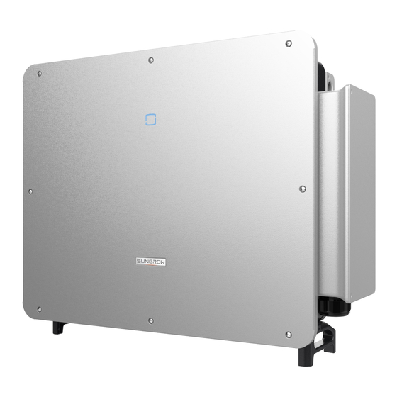
Page 16: Appearance
2 Product Description User Manual Table 2-1 Power Level Description T T y y p p e e N N o o m m i i n n a a l l O O u u t t p p u u t t P P o o w w e e r r N N o o m m i i n n a a l l G G r r i i d d V V o o l l t t a a g g e e SD125HV 125kW... -
Page 17: Dimensions And Weight
User Manual 2 Product Description D D e e s s c c r r i i p p t t i i o o n n N N o o . . N N a a m m e e Auxiliary To safely cut off the electrical connection between the con- power switch... -
Page 18: Dc Switch
2 Product Description User Manual L L E E D D i i n n - - L L E E D D s s t t a a t t e e D D e e f f i i n n t t i i t t i i o o n n d d i i c c a a t t o o r r Slow flash The device is in standby or startup state (not... -
Page 19: Emergency Stop Button
User Manual 2 Product Description F F i i g g u u r r e e 2 2 - - 5 5 Bottom view 2.2.6 Emergency Stop Button Press the emergency stop button to quickly stop the machine in an emergency. The po- sition is shown in the figure below. -
Page 20: Function Description
2 Product Description User Manual F F i i g g u u r r e e 2 2 - - 7 7 Circuit diagram 2.4 Function Description The converter is equipped with the following functions: C C o o n n v v e e r r s s i i o o n n Convert the DC power in the converter or battery into DC power that can be accepted by the equipment on the other side. -
Page 21: Unpacking And Storage
Check the inner contents for damage after unpacking. • Contact SUNGROW or the transport company in case of any damage or incomplete- ness, and provide photos to facilitate services. Do not dispose of the original packing case. It is recommended to store the device in the original packing case when the device is decommissioned. - Page 22 D D e e s s c c r r i i p p t t i i o o n n I I t t e e m m SUNGROW logo and product type Technical data of converter Instructions and marks of conformity...
-
Page 23: Converter Storage
User Manual 3 Unpacking and Storage 3.3 Converter Storage Store the converter properly when the converter is not to be installed immediately. Store the converter in the original packing case with the desiccant inside. • The storage temperature should be always between -40℃ and +70℃, and the sto- •... -
Page 24: Mechanical Mounting
Mechanical Mounting Respect all local standards and requirements during mechanical installation. 4.1 Safety during Mounting Make sure there is no electrical connection before installation. In order to avoid electric shock or other injury, be sure there is no electricity or plumbing installations before drilling holes. -
Page 25: Carrier Requirements
User Manual 4 Mechanical Mounting The converter should be protected against exposure to direct sunlight, rain, or snow • to ensure longer service life. The converter should be well ventilated. Ensure air circulation. • The converter should be installed at a location that is at least 30m away from third •... -
Page 26: Moving The Converter
4 Mechanical Mounting User Manual F F i i g g u u r r e e 4 4 - - 1 1 Installation Tools D D e e s s c c r r i i p p t t i i o o n n I I t t e e m m M4/M6 Drill bit: φ12、φ14... -
Page 27: Preparation Before Mounting
User Manual 4 Mechanical Mounting Always concerned about the weight of the converter. • Lift and move the inverter to the destination by using the side handles. • It is recommended to have two installers move the converter together or use proper •... - Page 28 4 Mechanical Mounting User Manual S S p p e e c c i i f f i i c c a a t t i i o o n n I I t t e e m m Including 16mm socket Socket wrench Opening: 16mm Wrench...
-
Page 29: Electrical Connection
Electrical Connection 5.1 Safety Instructions High voltage may be present inside the converter! • Do not connect DC circuit breakers before finishing electrical connections. • Ensure all cables are voltage free before performing cable connection. • Any improper operations during cable connection can cause device damage •... -
Page 30: Electrical Connection Overview
5 Electrical Connection User Manual F F i i g g u u r r e e 5 5 - - 1 1 Wiring terminals *Image shown here is for reference only. The actual product you receive may differ. I I t t e e m m T T e e r r m m i i n n a a l l M M a a r r k k N N o o t t e e... - Page 31 D D e e s s i i g g n n a a t t i i o o n n I I t t e e m m Battery Converter SD175HV Power conversion equipment such as inverters and battery storage converters...
-
Page 32: Additional Grounding Connection
DC3 connects to the DC battery storage terminal of the inverter. The length of the cable is less than 10 meters. Make sure that the cable is straight and flat during on-site installation. Do not twist the cable. Contact Sungrow if the appli- cation area is beyond the range. -
Page 33: Dc Cable Connection
User Manual 5 Electrical Connection 1:Heat shrink tubing 2:OT/DT terminal Step 2 Unscrew the screw on the side of the converter, fasten the cable with a screw driver. Step 3 Apply silica gel or paint the grounding terminal to improve its anti-corrosion performance. - Page 34 5 Electrical Connection User Manual Step 2 Strip insulation layers of all DC cables. Step 3 Dismantle the connector. Step 4 Pass the cable through the nut, clamping claw and sealing ring in that order. Insert the cable end into the base of the connector, and use the hexagonal crimping tool to press it tightly.
-
Page 35: Pv Connector Connection
User Manual 5 Electrical Connection C C o o - - N N a a m m e e R R e e c c o o m m m m e e n n d d e e d d V V a a l l u u e e d d e e 50mm²:9.2mm Crimping... - Page 36 5 Electrical Connection User Manual Step 3 Lead the cable through the cable gland, and insert it into the insulator until it snaps into place. Gently pull the cable backward to ensure a firm connection. Tighten the cable gland and the insulator with a torque of 2.5 N.m to 3 N.m. Step 4 Screw the nut.
-
Page 37: Ethernet Connection
Arc or contactor over-temperature may occur if the PV connectors are not firmly in place, and SUNGROW shall not be held liable for any damage caused. - - - - E E n n d d 5.7 Ethernet Connection... -
Page 38: Communication Connection
5 Electrical Connection User Manual Step 3 Remove the waterproof sealing plug and clamping claws. Step 4 Thread the network cable through the waterproof nut, clamping claw and sealing plug, and then tighten the nut. Step 5 Remove the protective cap of the communication terminal and insert the ethernet cable line into it, and screw tight. - Page 39 User Manual 5 Electrical Connection S S i i g g n n a a l l D D e e f f i i n n i i t t i i o o n n C C o o d d e e COMM1-1 COMM1-2 HN_COMHN...
- Page 40 5 Electrical Connection User Manual S S i i g g n n a a l l D D e e f f i i n n i i t t i i o o n n C C o o d d e e DSP_CANH COMM2-14 COMM2-15...
- Page 41 User Manual 5 Electrical Connection Step 3 Remove the waterproof protective cap and thread the network cable. Step 4 Strip the protection layer and insulation layer by appropriate length. Step 5 Thread the connector with the network cable and secure them on the wiring block. Step 6 Put the wiring block back into the connector.
- Page 42 5 Electrical Connection User Manual Step 7 Screw the nut. Step 8 Remove the protective cap of the communication terminal and insert the communica- tion connector. - - - - E E n n d d...
-
Page 43: Commissioning
Commissioning 6.1 Inspection before Commissioning Check the following items before starting the converter: The converter is correctly installed and secure. • The converter DC switch and external circuit breaker are disconnected. • All cables and auxiliary parts are properly connected and fastened. •... -
Page 44: Isolarcloud App
iSolarCloud APP 7.1 Brief Introduction The iSolarCloud APP can establish communication connection to the converter via the Bluetooth, thereby achieving near-end maintenance on the converter. Users can use the APP to view basic information, alarms, and events, set parameters, or download logs, etc. -
Page 45: Login
User Manual 7 iSolarCloud APP 7.3 Login 7.3.1 Requirements The following items should meet requirements: The DC sides of the converter is powered-on. • The mobile phone is within 5m away from the converter and there are no obstruc- • tions in between. -
Page 46: Home Page
• word for account security. To set converter parameters related to grid protection and grid support, • contact SUNGROW to obtain the advanced account and corresponding password. - - - - E E n n d d 7.4 Home page After login, the home page is as "Figure 7-3 Home... - Page 47 User Manual 7 iSolarCloud APP F F i i g g u u r r e e 7 7 - - 3 3 Home page Table 7-1 Home page description D D e e s s i i g g n n a a - - D D e e s s c c r r i i p p t t i i o o n n N N o o .
- Page 48 7 iSolarCloud APP User Manual D D e e s s i i g g n n a a - - D D e e s s c c r r i i p p t t i i o o n n N N o o .
-
Page 49: Running Information
User Manual 7 iSolarCloud APP 7.5 Running Information Tap“R R u u n n n n i i n n g g I I n n f f o o r r m m a a t t i i o o n n ”on the navigation bar to enter the running information screen, as shown in "Figure 7-4 Running Information". -
Page 50: Fault Alarm Records
7 iSolarCloud APP User Manual F F i i g g u u r r e e 7 7 - - 5 5 History record The user can view faults and alarm records, charging and discharging records, and events from "Records". 7.6.1 Fault Alarm Records Tap“... -
Page 51: Power Yields Records
User Manual 7 iSolarCloud APP Select one of the records in the list and click the record, to view the detailed fault info as shown in "Figure 7-7 Detailed fault alarm information"; F F i i g g u u r r e e 7 7 - - 7 7 Detailed fault alarm information 7.6.2 Power Yields Records User can view various energy records: power curve, daily energy histogram, daily en- ergy histogram, monthly energy histogram, and annual energy histogram. -
Page 52: Event Records
7 iSolarCloud APP User Manual F F i i g g u u r r e e 7 7 - - 8 8 Power curve Step 2 Tap the time bar on the top of the screen to select a time segment and view the corre- sponding power curve. -
Page 53: More
User Manual 7 iSolarCloud APP 7.7 More Tap“M M o o r r e e ”on the navigation bar to enter the "More" screen, as shown in "Figure 7-9 More". F F i i g g u u r r e e 7 7 - - 9 9 More 7.7.1 Boot Step 1 Click“... -
Page 54: Shutdown
7 iSolarCloud APP User Manual F F i i g g u u r r e e 7 7 - - 1 1 1 1 Hot Standby Step 2 Click "CONFIRM" to initiate hot standby. - - - - E E n n d d 7.7.3 Shutdown Step 1 Click“... -
Page 55: Settings
User Manual 7 iSolarCloud APP F F i i g g u u r r e e 7 7 - - 1 1 3 3 System Parameters 7.7.5 Settings Click“S S e e t t t t i i n n g g s s ” to go to the parameter configuration page as shown in "Figure 7-14 Settings". - Page 56 7 iSolarCloud APP User Manual F F i i g g u u r r e e 7 7 - - 1 1 4 4 Settings Table 7-4 Parameter Settings Description R R a a n n g g e e P P a a r r a a m m e e t t e e r r D D e e f f a a u u l l t t v v a a l l u u e e System Parameters...
- Page 57 User Manual 7 iSolarCloud APP R R a a n n g g e e P P a a r r a a m m e e t t e e r r D D e e f f a a u u l l t t v v a a l l u u e e Constant Current/Constant Set working mode Voltage/Constant Power/...
- Page 58 7 iSolarCloud APP User Manual R R a a n n g g e e P P a a r r a a m m e e t t e e r r D D e e f f a a u u l l t t v v a a l l u u e e Battery Discharge SOC Lower 0~99.9 Limit(%)
- Page 59 User Manual 7 iSolarCloud APP R R a a n n g g e e P P a a r r a a m m e e t t e e r r D D e e f f a a u u l l t t v v a a l l u u e e Battery undervoltage level-3 0.02~300 protection time(s)
- Page 60 7 iSolarCloud APP User Manual R R a a n n g g e e P P a a r r a a m m e e t t e e r r D D e e f f a a u u l l t t v v a a l l u u e e Timing Charge &...
- Page 61 User Manual 7 iSolarCloud APP R R a a n n g g e e P P a a r r a a m m e e t t e e r r D D e e f f a a u u l l t t v v a a l l u u e e Start time 5: minute 0~59 End time 5: hour...
- Page 62 7 iSolarCloud APP User Manual R R a a n n g g e e P P a a r r a a m m e e t t e e r r D D e e f f a a u u l l t t v v a a l l u u e e Work Mode 9 Not Operated/Charge/ Not Operated...
- Page 63 User Manual 7 iSolarCloud APP R R a a n n g g e e P P a a r r a a m m e e t t e e r r D D e e f f a a u u l l t t v v a a l l u u e e Preferred DNS server 4 0~255 Alternate DNS server 1...
-
Page 64: System Decommissioning
System Decommissioning 8.1 Disconnecting the Converter For maintenance or other service work, the converter must be switched off. Please follow the instructions below to disconnect the converter and DC power supply. Failure to do so may lead to equipment damage or result in death or injury. Step 1 Disconnect the external DC breaker and spin the DC switch of the converter to "OFF". - Page 65 User Manual 8 System Decommissioning The battery, module and other components in the converter may pollute the en- vironment. Dispose them in accordance with the applicable rules and regulations.
-
Page 66: Troubleshooting And Maintenance
4. Check whether the fan is running properly. Replace the fan if not; 5. If the fault is not caused by the foregoing reasons and still exists, please contact Customer Service of Sungrow Energy Storage Technology Co., Ltd. Check whether the communication cable is connected cor- BMS Com- rectly. -
Page 67: Maintenance
If you need any maintenance service, please contact Sungrow Power After- Sales Service Center. Otherwise Sungrow Power shall not provide any warranty or be held liable for any losses due to such negligence. - Page 68 9 Troubleshooting and Maintenance User Manual I I t t e e m m M M e e t t h h o o d d M M e e t t h h o o d d Check the temperature and dust of the con- verter.
-
Page 69: Appendix
10 Appendix 10.1 Technical Data P P a a r r a a m m e e t t e e r r s s Power Rated power 175kW Battery Maximum DC voltage 1500V Working voltage range 500~1500V Maximum DC current 160A Maximum DC voltage 1500V... -
Page 70: Quality Assurance
E E x x c c l l u u s s i i o o n n o o f f L L i i a a b b i i l l i i t t y y In the following circumstances, SUNGROW has the right to refuse to honor the quality guarantee: The free warranty period for the whole machine/components has expired. - Page 71 User Manual 10 Appendix Serial number of the device • Fault code/name • Brief description of the problem • For detailed contact information, please visit: h h t t t t p p s s : : / / / / e e n n . . s s u u n n g g r r o o w w p p o o w w e e r r . . c c o o m m / / c c o o n n t t a a c c t t U U S S...
Need help?
Do you have a question about the SD175HV and is the answer not in the manual?
Questions and answers
pelease sent me the user manual, i cannt download the document,