Table of Contents
Advertisement
Quick Links
Advertisement
Table of Contents

Related Manuals for Additel 260Ex


Summary of Contents for Additel 260Ex
- Page 1 260Ex Handheld Multichannel Reference Recorder...
- Page 2 ADT260Ex Handheld Multichannel Reference Recorder -------User Manual [Version:2211V01] Additel Corporation...
- Page 3 This user manual provides operating and safety instructions for the ADT260Ex Handheld Multichannel Reference Recorder. To ensure correct operation and safety, please follow the instructions in this manual. Additel Corporation reserves the right to change the contents and other information contained in this manual without notice.
-
Page 4: Table Of Contents
Content Safety instructions ................................1 Special safety requirements ............................. 2 Intended use ..................................6 1. Introduction ................................... 7 1.1 Product Overview ..............................7 1.2 Technical specification ............................8 1.2.1 General specification ............................8 1.2.2 Signal measure specification (environmental temp.: 20±10℃, 1 year accuracy) ........10 1.2.3 Simulate RTD measure accuracy (environmental temp.: 20±10℃) ............ - Page 5 3. Data logger .................................. 22 3.1 Pressure Measurement ............................23 3.2 RTD measurement ............................... 25 3.3 Electrical signal measurement ..........................26 3.3.1 DC Voltage measurement .......................... 26 3.3.2 Current measurement ..........................26 3.3.3 Switch measurement ..........................27 3.3.4 Pulse measurement ........................... 27 3.3.5 Frequency measurement ...........................
- Page 6 4.5.2 Language ..............................33 4.5.3 Date & Time ............................... 33 4.6 Product information .............................. 34 5. Data management ............................... 35 6. Data logger .................................. 36 6.1 Display mode ............................... 36 6.1.1 Single-channel mode ..........................36 6.1.2 Multi-channel list mode ..........................38 6.2 Channel data ................................
- Page 7 Figure Content Figure 1 Basic Structure ..............................14 Figure 2 Adaptor and the power plug ..........................17 Figure 3 Main interface..............................18 Figure 4 Control center..............................20 Figure 5 Calibrator main screen ............................23 Figure 6 RTD measurement .............................. 25 Figure 7 Voltage/ frequency/ pulse/ switch wiring ......................
-
Page 8: Safety Instructions
Before using the product, please check the appearance of the product for any damage; If the product is damaged or malfunctions, do not use it, and contact Additel; Do not touch the metal part of the probes or test cables during use;... -
Page 9: Special Safety Requirements
Special safety requirements 1. WARNING – DO NOT OPEN WHEN AN EXPLOSIVE ATMOSPHERE IS PRESENT 2. WARNING – DO NOT CHARGE THE BATTERY IN HAZARDOUS LOCATION 3. WARNING – USE ONLY the approved batteries, see Ex instruction 4. The equipment should be protected from high energy impacts 5. - Page 10 13. Do not remove the silicone rubber protective sleeve from the enclosure of equipment in Hazardous area 14. IS parameters must be observed for different external measuring ports on the different models in accordance with Ex instruction strictly and completely 15.
- Page 11 Po ≤ Pi Co ≥ Ci+Cc Lo ≥ Li+Lc Standard Compliance EN IEC 60079-0:2018 EN 60079-11:2012 IEC 60079-0:2017 Edition 7.0 IEC 60079-11:2011 Edition 6.0 Ex information for equipment name National regulations: ATEX directive 2014/34/EU and IECEx scheme 02 ...
- Page 12 Additel 260Ex Handheld Multichannel Reference Recorder Input parameters, simple connection Connection Function Ui/V Ii/mA Pi/mW Ci/nF Li/mH J1, J3 HART (external power and external resistance) J2, J3 Current measurement J4, J3 Voltage, frequency, and switch measurement Loop Circuit Transmitter Current Measuring /...
-
Page 13: Intended Use
Output parameters, simple connection Connection Function Uo/V Io/mA Po/mW Co/µF Lo/mH HART (external power and external J1, J3 25.2 79.16 0.107 resistance) J2, J3 Current measurement 0.85 Voltage, frequency, and switch J4, J3 0.85 measurement Loop Circuit Transmitter Current J1, J2 Measuring / HART(Internal Power and 25.2 79.16... -
Page 14: Introduction
1. Introduction 1.1 Product Overview ADT260EX is an intrinsically safe pressure and temperature logger provided by Additel. It can be used in zone 0 environment and has an 8-channel combination capability, supports measurement and logging of pressure, temperature, barometric pressure and electrical signals. It can keep 10 million records, display the trend curve, and support Bluetooth communication. -
Page 15: Technical Specification
1.2 Technical specification 1.2.1 General specification Table 1 General specification General Specification Top: 2 channels RTD measurement, 1 channel electric signal measurement, φ4mm banana jacks Right side: 2 channels for external digital pressure module, Lemo style connection Input Channel Bottom: embedded digital pressure module (model ADT158Ex) field switchable. Internal: 1 embedded atmospheric pressure sensor Barometric Accuracy ±55Pa... - Page 16 Operating temperature: (-20 ~ 50)°C Storage temperature range: (-30 ~ 70)°C Humidity: 0% to 95% RH, non-condensing Altitude: 3000 meters Warm Up Time 10 minutes to fully meet technical specifications Port Protection Voltage 30V max ATEX & IECEX: Ex ia IIC T4 Ga (Ta = -20°C to +50°C) CSA: Class I, Division 1, Group A,B,C and D, T4 Class I, Zone 0, AEx ia IIC T4 Ga Explosion-proof Grade Ta = -20°Cto + 50°C Ex ia IIC T4 Ga...
-
Page 17: Signal Measure Specification (Environmental Temp.: 20±10℃, 1 Year Accuracy)
1.2.2 Signal measure specification (environmental temp.: 20±10℃, 1 year accuracy) Table 2 Signal measure specification Specification Range Accuracy Resolution Note RTD Measurement 0.01%RDG+0.005%FS [1] 1mΩ Excitation current: 1 mA 0~400Ω Accuracy Impedance: >100MΩ ±300mV 0.015%RDG + 0.005%FS Voltage Measurement Impedance: >1MΩ ±30V 0.015%RDG + 0.005%FS 0.1mV... -
Page 18: Simulate Rtd Measure Accuracy (Environmental Temp.: 20±10℃)
(2) Voltage range:-30~30V input impedance >1MΩ; (3) Current measure: input impedance<40Ω; Note 3: The excitation power supply for RTD measure is 0.2mA, and each position has 4-wire, 3-wire, and 2-wire methods. The accuracy is as follows: (given accuracy data in the table in based on 4-wire) (1) The accuracy of the 3-wire method is 10mΩ... - Page 19 600~850 0.41 -200~200 0.16 PT50(385) -200~850 200~600 0.22 600~850 0.27 -200~200 0.10 PT100(385) PT100(391) -200~850 200~600 0.16 PT100(3916) PT100(3926) 600~850 0.20 -200~200 0.32 200~300 0.34 PT200(385) -200~850 300~600 0.41 600~850 0.48 -200~0 0.15 0~200 0.18 PT400(385) -200~850 200~600 0.25 0.30 600~850 -200~200 0.16...
- Page 20 200~600 0.16 600~850 0.20 Cu10(427) -200~260 -200~260 0.56 Cu50(428) -50~150 -50~150 0.13 Cu100(428) -50~150 -50~150 0.08 -60~0 0.06 Ni100(617) -60~180 Ni100(618) 0~180 0.05 Ni120 (672) -80~260 -80~260 0.05 Ni1000 -50~150 -50~150 0.07 Note: It complies with the international temperature scale ITS90, depends on the maximum tolerance of the RTD measurement and simulate signal output.
-
Page 21: Basic Structure
1.3 Basic Structure Figure 1 Basic Structure... - Page 22 Table 4 Basic Structure Subject Content Description Display+ capacitive touch screen Display area, touchable Keys For operating the device Lemo port A Connect to external pressure module. Lemo port B Connect to external pressure module. Adaptor port Power supply from adaptor. USB slave port For USB communication.
-
Page 23: Standard Package Include
ISO 17025 accredited calibration certificate 1 pc ADT158Ex Built-in digital pressure module ADT161Ex External digital pressure module 9530 Additel/ACal calibration software Optional 9060 Pressure module connection cable 9905 Hard carrying case for handheld calibrators and readouts with space for two RTDs 9918-SC Soft carrying case, with space for handheld instrument, test leads, and accessaries Note: in case of changes on the accessories list, please refer to the packing list in shipping. -
Page 24: Power Supply Description
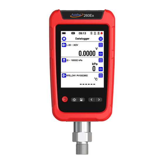
The power adaptor is adaptable for standard in various countries. Do not expose the battery to fire or short circuit the battery. Use only the Additel power adaptor and designated battery models. Figure 2 Adaptor and the power plug... - Page 25 2. Overview for display and basic functions The ADT260Ex will automatically go to Data Logger function after powered on. It can also be returned to main interface for all the functions. (Refer to Figure.3). Figure 3 Main interface...
-
Page 26: Main Interface
2.1 Main interface In the main interface, there are three sections from top to bottom: status bar, APPs list and main function guide, as shown in Figure 3. 2.1.1 Status bar On the top of the main interface shows the status information, including: System time: real-time of the system;... -
Page 27: Main Function Guide
2.1.3 Main function guide The main function guide at the bottom of the interface provides access to three main functions of the device: data logger, data manager and setup. Figure 4 Control center... -
Page 28: Control Center
2.2 Control center In any interface of the device, the control center (Figure 4 Control Center) can be called up by physical key . It provides detailed information of date, battery, diagnostic center, screenshot functions, and some shortcuts items. 2.2.1 Date and battery In the control center show the current date and precise battery percentage. -
Page 29: Data Logger
3. Data logger The ADT260Ex can be used for measuring and recording many signal types, including the signal of the internal pressure module, external pressure module A and B, differential pressure module, barometric pressure, 2-wire RTD and electrical signal measurement, totally 8 measurement features available. The electrical signal measurement supports voltage, current, switch, pulse, and frequency. -
Page 30: Pressure Measurement
Figure 5 Calibrator main screen 3.1 Pressure Measurement The device can measure the pressure by internal pressure module, external pressure module A/B, differential pressure, and barometer. The external pressure A and B are only available when the external pressure module is connected. - Page 31 two modules are online. Select the proper module in the Channel settings to measure the pressure. Click the pressure unit above the pressure measurement value to switch the pressure unit in the pop-up unit selection interface. Click the menu icon in the pressure measurement channel and click the "Settings"...
-
Page 32: Rtd Measurement
3.2 RTD measurement The connection of RTD measurement is shown in figure 6. Click the switching menu and select the RTD measurement Figure 6 RTD measurement Click the "Settings" of the RTD measurement channel to set various parameters for the functions. Table 7 RTD settings Subject Valid Value... -
Page 33: Electrical Signal Measurement
3.3 Electrical signal measurement 3.3.1 DC Voltage measurement Please connect correctly as shown in the figure 7. Then switch the measurement signal to voltage measurement. To ensure measurement accuracy and adapt to more usage scenarios, two different ranges can be selected for voltage measurement in this device: (-30~30)V and (-300~300)mV , the user should select the appropriate... -
Page 34: Switch Measurement
3.3.3 Switch measurement Figure 8 Current measurement The wiring method of the switch measurement function is the same as the voltage measurement. After wiring, please switch the measurement signal channel to switch measurement 3.3.4 Pulse measurement The wiring method of the pulse measurement function is the same as the voltage measurement. After wiring, please switch the measurement signal channel to (0 ~9999999) . -
Page 35: Filtering
switch the measurement signal channel to frequency measurement (0.01~50k)Hz 3.4 Filtering The ADT260Ex provides two filtering methods: first-order linear filtering and moving average filtering to process data to meet the needs of different scenarios. Click the menu button of the measurement channel, select the filter menu item in the pop-up menu, and the filter setting interface will be displayed (see Figure 9). -
Page 36: Scaling
Table 8 Filter configurations Subject Valid Value Description Enable/disable Enable/disable Enable or disable the filter function Method first-order linear filter or moving average filter Filtering method Filter coefficient 0 ~ 1 Only available when the first-order linear filter is selected Number of samples 1~50 Only available when the moving average filter is selected... - Page 37 Figure 10 Scaling configurations...
-
Page 38: System Settings
4. System settings On the main page of the device, click the system setting button in the middle of the bottom to enter the system setting interface. System maintenance, system calibration, and various basic system settings are provided in the system settings. -
Page 39: Services
2. Use a high-precision standard device, after fully warming up, follow the calibration guide in the interface and click the "Start" button to start the calibration. 3. According to the reference calibration point provided on the interface, select the appropriate standard value, and enter 4. -
Page 40: Personalization
4.5 Personalization Click the "Personalization" menu item in the system setting interface to enter the personalized setting interface. In the personalized setting interface, users can set the device's sound, language type, current time, and date, and time date format according to their own preferences. 4.5.1 Sound Change the sound level by adjusting the volume bar. -
Page 41: Product Information
Table 11 Date & time Subject Valid Value Comment Date Date setting 2000-1-1 ~ 2099-12-31 Time 00:00 ~ 23:59 Time setting Date format Y-M-D / M-D-Y / D-M-Y Date format setting Separator -,/,. Date separator setting 24 hours enable 24-hour or 12-hour format 4.6 Product information ◆... -
Page 42: Data Management
5. Data management On the main page of the device, click the file management button in the middle bottom to enter the data management interface. The file management interface is classified and managed by functional modules, and the data saved by each function is managed in the corresponding folder, which is convenient for users to browse. The functional modules that can save data files are: snapshot, data logger, PSV test and leak test. -
Page 43: Data Logger
6. Data logger The most important function of the device is the data logger. Click the menu icon at the top right of the main interface and click "Start logging" to enter the logging configuration interface. Here it is available to set the interval for each logging point and the total number &... - Page 44 Figure 11 Single-channel mode Click the data area to switch the channel mode. When the top right area shows , it means manual switch at present. Click the left and right icon or the physical direction key to switch the channels. When the top right area shows , it means automatic switch mode is activated, and the device will automatically switch to next channel every 5s or 30s.
-
Page 45: Multi-Channel List Mode
6.1.2 Multi-channel list mode Under this mode, there can be the curve or data of at most 3 channels to be displayed at one page, as shown in figure 12. The channel can fit with the sizes and when logging more than 3 channels, there will be the icon for page switching, click the icon or the physical direction key to switch between pages. -
Page 46: Channel Data
using curve, click the curve area to switch the curve mode. 6.2 Channel data It includes the real time measured value, maximum, minimum, average, peak to peak value and standard deviation. 6.3 Channel curve The Y axis of the channel curve can adapt to the scale based on current value. The curve supports following mode (1x, 2x and 4x) and eye pattern mode. -
Page 47: Applications
7. Applications 7.1 Differential pressure module The ADT260Ex provides the function of combining two pressure modules (any 2 of the internal pressure module, external pressure module A and B) into a differential pressure module. This provides a convenient differential pressure(DP) test solution in a high static pressure environment. The set parameters of the DP module are shown in the table below. -
Page 48: Units Converter
Zero offset generated by performing Zero offset when performing differential pressure module Zero offset zeroing zeroing Pressure module A S/N of the pressure module Pressure module B S/N of the pressure module Perform zero to the differential pressure module, the zero Zero offset will be saved and used for calculation Cancel the zero-offset created when performing the zero, reset... -
Page 49: Leak Test Performing
the pressure module column to set the test parameters, see the table below: Table 13 Leak test setting Subject Valid value Description The pressure type being recorded, view detail according to Pressure type GP/ AP device’s module Pressure unit Pressure unit Select corresponding pressure unit Waiting time Numbers... -
Page 50: Psv Test
2. The entire process will be displayed in stages in the leak curve at the bottom of the screen. 7.5 PSV test The device provides function of PSV test, to test the safety pressure of the safety valves. Click the pressure module on the top, to set relevant parameters, see table below: Table 14 PSV test setting Subject... -
Page 51: Sensor Library
7.6 Sensor library To meet the needs of custom sensor types, the ADT260Ex provides a sensor library function. In the sensor library function, users can define new sensor types according to their needs and set relevant parameters in the sensor. The sensor library supports a total of four types of custom sensors: ITS-90, CVD, RTD and TC.
Need help?
Do you have a question about the 260Ex and is the answer not in the manual?
Questions and answers