Table of Contents
Advertisement
Quick Links
Advertisement
Table of Contents

Related Manuals for Additel ADT685


Summary of Contents for Additel ADT685
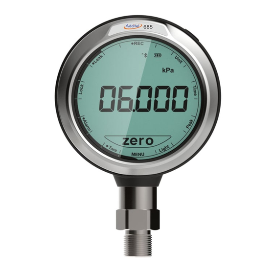
- Page 1 685/685Ex Advanced Digital Pressure Gauge...
- Page 2 ADT685/685EX Advanced Digital Pressure Gauge -------User Manual [Version:2103V01] Additel Corporation...
- Page 3 This user manual provides operating and safety instructions for the ADT685/685EX Advanced Digital Pressure Gauge. To ensure correct operation and safety, please follow the instructions in this manual. Additel Corporation reserves the right to change the contents and other information contained in this manual without notice.
-
Page 5: Table Of Contents
CONTENT 1. INTRODUCTION ................................3 1.1 General Introduction ..............................3 1.2 Pressure Ranges and Accuracy ..........................4 1.3 Technical Specifications ............................. 9 1.4 Features ................................... 10 1.5 Basic Structure ................................. 11 2. OPERATION ................................. 13 2.1 Main Display ................................13 2.2 Main Operation Interface ............................ - Page 6 2.8 Backlight ON/OFF ..............................26 2.9 Screen Lock and Unlock ............................27 2.10 Date and Time ................................ 27 2.11 Password Display and Editing ..........................29 2.12 Number Editing............................... 30 2.13 Cycle Selection Keyboard Display and Editing ......................31 3. SYSTEM SETTINGS..............................32 3.1 Communications ..............................
- Page 7 3.7.1 Version Snformation ............................44 3.7.2 Resolution Settings ............................44 3.7.3 Auto-backlight Time Settings ..........................44 3.7.4 Barometric Pressure and Temperature Display ....................44 3.7.5 Overpressure Record Information ........................45 3.7.6 Touch Sound Settings ............................45 3.8 Malfunction Information ............................45 3.9 Operation Error Codes .............................
- Page 9 Please be sure to store, transport and use this product in the correct direction; ◆ ◆ If the product is damaged or malfunctions, please do not use it and contact Additel; ◆ Never use the non-Ex version in an explosive, steam or dust environment.
- Page 10 To prevent injury, please obey the instruction manual for use To prevent possible damage, please do as follows: ◆ Do not use the instrument in a high vibration environment; ◆ If the gauge is abnormal, please stop using it and contact with Additel.
-
Page 11: Introduction
The power consumption of ADT685/ADT685EX is very low, which is suitable for long-term continuous work (Up to 20,000 hours under ultra-low power consumption mode). The ADT685/ADT685EX also has excellent electromagnetic compatibility characteristics, it has obtained the CE certification of the most authoritative organization and can be used in various complex electromagnetic environments. -
Page 12: Pressure Ranges And Accuracy
1.2 Pressure Ranges and Accuracy Table 1 Gauge Pressure (Sealed gauge pressure for above 1,000 psi) Pressure Range Accuracy Media Burst Pressure (psi) (bar) -1.0 0.02 (0.05) 0.16 0.05 0.35 0.05 GP10 0.02 (0.05) GP15 0.02 (0.05) GP30 0.02 (0.05) GP50 0.02 (0.05) GP100... - Page 13 GP2K 2,000 0.02 (0.05) GP3K 3,000 0.02 (0.05) GP5K 5,000 0.02 (0.05) GP10K 10,000 0.02 (0.05) GP15K 15,000 1,000 0.05 (0.1) 1.5X GP20K 20,000 1,400 0.05 (0.1) 1.5X GP25K 25,000 1,600 0.05 (0.1) 1.5X GP30K 30,000 2,000 0.05 (0.1) 1.5X GP36K 36,000 2,500...
- Page 14 Table 2 Differential Pressure Static Pressure Range Accuracy Media Burst Pressure Pressure (%FS) (inH2O) (mbar) Range ±1 ±2.5 0.05 100X ±10 psi ±2 ±5.0 0.05 100X ±10 psi ±5 ±10 0.05 ±10 psi DP10 ±10 ±25 0.05 ±10 psi DP20 ±20 ±50 0.05...
- Page 15 Table 3 Compound Pressure Pressure Range Accuracy Media Burst Pressure (psi) (bar) ±2 ±0.16 0.05 ±5 ±0.35 0.02 (0.05) CP10 ±10 ±0.7 0.02 (0.05) CP15 ±15 ±1 0.02 (0.05) CP30 -15 to 30 -1 to 2 0.02 (0.05) CP100 -15 to 100 -1 to 7 0.02 (0.05) CP300...
- Page 16 Table 4 Absolute Pressure Pressure Range Media Accuracy (%FS) Burst Pressure (psi) (bar) 0.35 AP10 AP15 AP30 AP50 AP100 0.05(0.1) AP300 0.05(0.1) AP500 0.05(0.1) AP1K 1000 0.05(0.1) AP3K 3000 0.05(0.1) AP5K 5000 0.05(0.1) [1] G=Gas, L=Liquid. *Note ◆ Temperature Compensation:(-10~50)℃, 1year accuracy; ◆...
-
Page 17: Technical Specifications
1.3 Technical Specifications Table 5 Technical Specifications ADT685 ADT685Ex Model Digital Pressure Gauge Intrinsically Safe Digital Pressure Gauge Intrinsic Safety CE marked & ATEX certified intrinsically safe European Compliance II 1G EX ia IIC T4 Ga Protection Level IP67 Case Material... -
Page 18: Features
Range: (60~110) kPa.a, accuracy: 50Pa (Built-in barometer) [1] Wetted parts material types may vary by pressure range. Please refer to manual or contact Additel for more information. [2] 4-20 mA output and RS-485 not available in ADT685Ex models. 1.4 Features... -
Page 19: Basic Structure
1.5 Basic Structure Figure 1 Basic Structure... - Page 20 Table 6 Basic Structure Part Name Function LCD Display Back Light Button Turn on/off the back light Units Button Switch the pressure engineering units Zeroing/Clear Button Readings zeroing or to clear the number in number editing interface Long press to power on/off the gauge, Power On/Off / Reset Button short pressure to return to previous interface Switchable Communication Module...
-
Page 21: Operation
2.Operation 2.1 Main Display Main display as shown in Figure 2: Menu bar: To access to the main functions of the gauge Status bar: Including USB status, Bluetooth, battery, DIFF, absolute pressure and filtering status icons. The Bluetooth icon can be clicked to turn on or off Bluetooth, when the battery icon is blank and flashing, Bluetooth will be turned off automatically. -
Page 22: Main Operation Interface
Figure 2 Main Display 2.2 Main Operation Interface After the pressure gauge is turned on, it first displays the interface of the original range of the pressure module. 3 seconds later, it will enter the main interface immediately. The main interface display is divided into: menu bar, status bar, pressure unit display area, main value display area, and secondary value display area and Zero/OK button, as shown in Figure 3. - Page 23 Figure 3 Main Operation Interface 1. Menu Bar:The main interface displays the following menus, click the menu to enter or enable different functions: (1) Menu:Click to enter the system setting function interface, in other interfaces, the Menu button is used to return to the previous interface.
- Page 24 (4) P Type: Switch between gauge pressure and absolute pressure. When switching to absolute pressure, the ABS icon will be displayed on the status bar. If the pressure gauge does not support gauge/absolute pressure mode switching, the P Type menu will be hidden. (5) Leak: Enter the pressure leak test interface, see chapter 2.6.
-
Page 25: Buttons
2.3 Buttons Power ON/OFF Button: Long press 3 seconds to power on/off the gauge. In the data input state, it could delete the inputted data. In the menu state, it has the function of returning to the previous menu. Backlight Button: Short press this button to turn on/off the display backlight, long press this button to set the backlight duration time, there are five options: 10 seconds, 20 seconds, 30 seconds, 60 seconds, and ON (the backlight is always on). -
Page 26: Pressure Zeroing
Figure 4 Pressure percentage indication 2.4.1 Pressure Zeroing When the gauge is in gauge pressure mode, press Zero button to execute the pressure zeroing. If the zeroing operation fails, the pressure gauge will emit an error, and the Zero button will flash quickly to remind you. When in absolute pressure mode, the Zero button is not displayed on the main interface, and the zeroing operation cannot be performed. -
Page 27: Pressure Unit Switching
2.4.2 Pressure Unit Switching Click the unit and prompt information display area to switch the pressure units, touch the left half of the pressure unit area to switch to the previous pressure unit, and touch the right half to switch to the next pressure unit. 2.4.3 Pressure Type Switching Click P Type in the menu bar to switch the gauge/absolute pressure mode. - Page 28 Figure 5 Pressure peaks recording Table 7 Pressure peaks setting parameter table Items Introductions Maximum Value Minimum Value Zero Reset data...
-
Page 29: Pressure Leak Test
2.6 Pressure Leak Test 1. Click the Leak icon in the menu bar to enter the pressure leak test setting interface, as shown in Figure 6, the main value area displays the test time , press the up and down arrows to edit this value. Click the unit position to switch the pressure unit. - Page 30 2. In the pressure leak test operation interface, a black dot appears in front of the Leak menu, the main display area displays the countdown, and the sub display area displays the real-time pressure value, as shown in Figure 7. Figure7 Pressure leak test operation interface...
- Page 31 3. When the pressure leak test operation is finished, as shown in Figure 8, the icon appears in the status bar, and the differential pressure value is displayed in the main display area. Click the sub display area to switch between the start pressure value P1 and the end pressure value P2. Figure 8 Pressure leak test finish interface...
-
Page 32: Data Logging
2.7 Data Logging 1. Click Rec on the menu bar to enter the data logging setting interface, as shown in Figure 9, the main display area displays the real-time pressure value , the left side of the sub display area displays the logging interval , click it to edit the time interval, and the right side displays the used storage space in percentage, click it to delete the stored data. - Page 33 2. The pressure record operation interface, as shown in Figure 10. A small black dot appears in front of the REC menu, the main display area displays the real-time pressure value, the left side of the sub display area displays the number of recorded data , and the right side displays the percentage of storage space that has been used...
-
Page 34: Backlight On/Off
2.8 Backlight ON/OFF Short press Light icon in the menu bar, you can turn on and off the backlight function. Long press to enter the backlight setting interface, as shown in Figure 11, the main display area displays the automatic backlight turn off time, click it to edit the automatic backlight off time. -
Page 35: Screen Lock And Unlock
2.9 Screen Lock and Unlock Press the Lock icon on the menu bar to lock and unlock the screen. When entering the lock screen state, a dot is displayed in front of the Lock icon. At this time, only the Lock menu and the power button can be operated. Click other places on the screen or three other physical buttons, the Lock menu bar will flash to remind the pressure gauge has entered the lock screen state. - Page 36 Press the title bar of the time and date display interface to enter the time and date format setting interface, as shown in Figure 14. Figure14 Time and date format setting interface Press the title bar to select the date format, support Y-M-D, M-D-Y, D-M-Y three date formats. Press the main display area to enter to select time format, which includes 12-hour and 24-hour time formats.
-
Page 37: Password Display And Editing
2.11 Password Display and Editing When entering the pressure gauge calibration, restoring the factory settings, and clearing the data record function, the password keyboard will pop up. The password keyboard can edit each digit by press up and down arrows, click the OK button to confirm the password, and click the Menu icon or power button to cancel and return. -
Page 38: Number Editing
2.12 Number Editing The pressure gauge provides a number editing interface, as shown in Figure 16. Adjust the value by clicking the symbol area on the left side of the screen to switch the positive or negative sign. Click the OK button to confirm, click Menu icon or short press the power button to cancel and return. -
Page 39: Cycle Selection Keyboard Display And Editing
2.13 Cycle Selection Keyboard Display and Editing The gauge provides a cycle selection keyboard to set parameters, as shown in Figure 17. The main value area will flash to indicate that this area can be edited, and the main value area display can be switched by clicking the upper and lower edges of the main value area to cycle through the selections. -
Page 40: System Settings
Rate: Press to enter the pressure rate mode setting interface. 3.1 Communications Press the COMM icon to enter the communication setting interface, press the title bar to switch between different communication setting interfaces. 3.1.1 Bluetooth The gauge can communicate with the mobile App Additel Link via Bluetooth. - Page 41 Table 8 Wireless communication settings Items Effective Value Explanation Bluetooth ON/OFF The main display area displays the Bluetooth on/off status, click to set the Bluetooth switch status MAC Address Read Only The sub display area displays the Bluetooth MAC address (displayed from the second digit of the MAC address)
-
Page 42: Rs232/Rs485
3.1.2 RS232/RS485 When the RS232/RS485 module is enabled, the RS232/RS485 module setting interface will appear in the communication settings, as shown in Figure 18. The main display area displays the address , click to edit it. The left side of the sub display area displays the baud rate , click to enter to select the baud rate. -
Page 43: 4-20Ma
3.1.3 4-20mA 1. When the 4-20mA module is enabled, the range setting interface is shown in Figure 19. The sub display area provides the setting of the upper and lower limits of the range, and the unit is same as the main display unit of the gauge. -
Page 44: Switch Settings
Figure 20. 4-20mA loop current test interface 3.1.4 SWITCH Settings When the SWITCH module is enabled, the setting interface is shown in Figure 21. SWITCH is associated with the pressure alarm in section 2.4.6, the main display area shows ALARM, and the output state is ON or OFF, click the main display area to switch. -
Page 45: Auto Power Off Settings
Figure21 Switch module setting interface 3.2 Auto Power Off Settings Press the Auto Off icon on menu bar to enter the auto power off setting, click the title bar to turn on or off the auto power off function, in the open state, click the main value display area to edit the auto power off time 3.3 Filter Settings Press the Filter icon in the menu bar to enter the filter setting interface and click the title bar to cycle through the filter modes: off, first-order filtering, and average filtering. -
Page 46: Pressure Reading Display Rate
area displays the number of extreme value pairs will be removed, click to edit. Table 9 Filter Settings Item Effective Value Explanation Filtering ON/OFF Filter ON or OFF Filter Modes First-order filtering / Average filtering Choose the filter modes Coefficient 0.05~1 First-order filtering mode is applicable Number of filtered samples... -
Page 47: Calibration
The sub display area sets the system low power consumption mode. When the optional module is not a 4-20mA transmitter module, the low power consumption mode open or close settings will be displayed in this area. Click the sub display area to enter to edit low power mode. When the low power consumption mode is turned on, an icon will appears on the main interface, then the touch screen will be turned off, and the system will enter a low power consumption state. -
Page 48: Pressure Calibration
Figure22 Calibration Interface 3.5.2 Pressure Calibration 1. Two-point calibration. The default calibration points are the upper and lower limits of the range. The sequence of calibration is to calibrate the lower limit first and then the upper limit, as shown in Figure 23 for the lower limit of calibration. - Page 49 the range. The sequence of calibration is to calibrate the lower limit first, then zero point, and finally the upper limit. After the upper limit is finished, return to the calibration setting interface. 4. Cancel calibration: In the pressure calibration setting interface, click the main display area to the cancel calibration interface, and click OK to cancel the calibration data.
-
Page 50: Barometric Calibration
3.5.3 Barometric Calibration Provide single point calibration, two points calibration and cancel calibration. Before the calibration, please open the battery cover of the gauge, and connect the pressure hose to the φ4 pressure port, as shown in figure 24. Figure24 Barometric calibration connection The barometric calibration interface is shown in Figure 25. -
Page 51: 20) Ma Calibration (Only Available When Using (4~20) Ma Module)
calibration interface, the main display area displays the measured value of barometric pressure, the left side of the sub display area indicates the current calibration point, and the right side indicates the standard value, it can be clicked to edit. Click OK to enter the next point, and finally submit the calibration data to complete the calibration. Figure25 Barometric calibration selection interface 3.5.4 (4~20) mA Calibration (only available when using (4~20) mA module) When the (4~20) mA module is enabled, the module can be calibrated. -
Page 52: Restore To Factory Settings
3.6 Restore to Factory Settings Press the Restore icon in the menu bar to enter the interface of restore factory settings. To enable this function, you need to enter a password. The default password is: 123456. Click OK to perform the factory restore operation, click Menu or short press the power button to return to the previous menu. -
Page 53: Overpressure Record Information
3.7.5 Overpressure Record Information The title bar displays OVER P, Press the main display area to switch to the next overpressure record information, the main display area displays the total number of overpressure records, the current serial number, the sub display area displays the overpressure value, short press the sub display area to switch to display the date and time of the overpressure record. - Page 54 Perform the manufacturer restore, if Flash init failed the fault still, please contact the manufacturer Switch off and start again, if the fault Bluetooth module init failed still, please contact the manufacturer Battery low voltage Change the battery Battery over voltage Change the battery 1001 Pressure module: constant circuit resistance failed...
-
Page 55: Operation Error Codes
pressure sensor short circuit failed 1092 Pressure module: constant circuit resistance failed 1101 Pressure module: constant voltage excitation failed 1111 Pressure module: internal EEPROM failed 1121 Pressure module: external EEPROM failed 1131 Note: In case of it cannot be turned on, please firstly open the cover of the pressure gauge, replace the battery and press the power button to turn it on again. -
Page 56: Copyright
4.Copyright Additel owns all copyrights to this system and reserves all rights. Please respect the rights of our company. Appendix A:RS232 module DB9 Pins Description Figure 26 RS232 module DB9 female pins description Table12 RS232 module DB9 pins description Pins... -
Page 57: Appendix B:rs485 Module Db9 Pins Description
Reserved Reserved Reserved Reserved Reserved Appendix B:RS485 module DB9 Pins Description Figure27 RS485 module DB9 female pins description... - Page 58 Table13 RS485 module DB9 pins description Pins Description Reserved Reserved Reserved Reserved Reserved Reserved...
-
Page 59: Appendix C:switch Module Pins Description
Appendix C:SWITCH Module Pins Description Figure28 SWITCH module pins description Table14 SWITCH module pins description Pins Description Reserved Reserved Reserved Reserved... -
Page 60: Appendix D:dual Cable (4~20) Ma Module Pins Description
Reserved Reserved Note: [1] Switch node output characteristics: open-drain output, internal resistance of 100Ω when turned on, and maximum external voltage of 30V. [2] Ex gauges do not support SWITCH module. Appendix D:Dual Cable (4~20) mA Module Pins Description Figure26 Dual cable (4~20)mA module female pins description... -
Page 61: Appendix E:special Notice For Adt685Ex Cable
Table14 Dual cable (4~20)mA module female pins description Pins Description L00P+ L00P- Note: [1] Power supply range:DC 12V~36V [2] Transmission output accuracy level (including pressure, -10℃~50℃ full temperature compensation): 0.05/0.1/0.2 [3] Only non-Ex proof version is supported Appendix E: Special Notice for ADT685Ex Cable Any data download devices connected to the Digital Pressure Gauge shall be approved SELV or Class 2 equipment against IEC 60950 or an equivalent IEC standard. -
Page 62: Appendix F:adt685Ex Ex-Proof Description
Appendix F:ADT685Ex EX-Proof Description Conform the CE, CSA, UKCA and IECEx certification: 1. ATEx certificate:II 1 G Ex ia IIC T4 Ga Ta=-20℃to+50℃ IECEx SIR 21.0018X CSANe 21ATEx2078X 2. CSA certificate:Class I,Division 1,Groups A,B,C and D,T4 Class I,Zone 0,AEx ia IIC T4 Ga CSA 21CA 80045682X Ta=-20℃to+50℃...
Need help?
Do you have a question about the ADT685 and is the answer not in the manual?
Questions and answers