Table of Contents
Advertisement
Quick Links
Advertisement
Table of Contents

Related Manuals for Atkinson Electronics GSCM-mini


Summary of Contents for Atkinson Electronics GSCM-mini
- Page 1 Generator Start Control Module Part# GSCM-mini-d ATKINSON ELECTRONICS, INC. 14 West Vine Street · Murray, Utah 84107 Contact cbdsales@atkinsonel.com for the proper hookup diagram. Please include the generator make & model, inverter brand, & battery bank voltage.
-
Page 2: Table Of Contents
Outback 48 Volt inverter and start the generator to charge its own battery if systems require isolation relay connected to pin 4. The GSCM-mini-d is a limited A0365 function controller that is part of the GSCM family. All auto start battery voltage thresholds are fixed, if adjustability is required use the GSCM full function Generator Start Control Module. -
Page 3: Led Indication Description
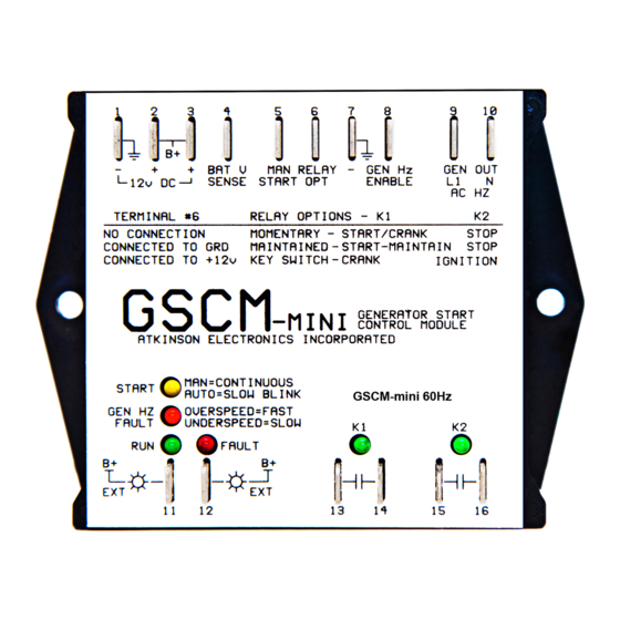
Three Modes of Relay Operation LED Indication Description The GSCM-mini-d has six indication LEDs. There are 3 different options for the GSCM-mini-d’s The Start LED blinks once every 5 seconds to indicate it is Momentary, two relay contacts to be configured: ready for a start signal. - Page 4 GSCM-mini-d Wiring Diagram Example www.atkinsonelectronics.com Circuit Board Division 800.261.3602 Revised 11/2020...
-
Page 5: Option 1 Diagram
Typical Generator with Starter Control Box The GSCM-mini-d option 1 provides the same momentary glow plug operation for those 3 wire diesel applications where the key switch or off button is pressed for 10 seconds energizing the glow plugs, then the start button is pressed starting the generator. The GSCM-mini-d energizes K2 for 10 seconds to heat the glow plugs, then energizes K1 relay, providing the start signal to start/crank input and removes it when the generators AC output has reached 45Hz or half speed. - Page 6 1. The start LED blinks once every 5 seconds to indicate that the GSCM-mini-d is in a ready mode. When a manual signal is received, the start LED lights continuously. After a 2 second delay, the K2 relay closes for 10 seconds then opens, the K1 relay closes to crank the starter and remains closed until either the generator starts or the maximum cranking time period of 20 seconds is reached.
-
Page 7: Option 2 Starting Sequence
5 seconds. The generator starting sequence is as follows. 1. The start LED blinks once every 5 seconds to indicate that the GSCM-mini is in a ready mode. When a manual start signal is received, the start LED lights continuously. After a 2 second delay, K1 relay closes to start the generator. The K1 relay remains closed until either the start signal is removed or the maximum cranking time of 1 minute is reached. -
Page 8: Option 3 Starting Sequence
. The generator starting sequence is as follows: 1. The start LED blinks once every 5 seconds to indicate that the GSCM-mini is in a ready mode. When a manual signal is received, the start LED lights continuously. After a 2 second delay, K2 relay energizes and remains energized until the start signal is either removed or the generator fails to start after 3 attempts. -
Page 9: Manual Off Auto Switch Options
LED on continuously. 5. Generator shuts down on its own fault. While the GSCM-mini is in run mode, and the generator is running, if the generator shuts down on a fault condition (low oil pressure, hi temperature, or out of fuel) or the AC Hz signal fuse or wire opens or the 12V run status wire opens, the GSCM-mini goes thru its shutdown routine and enters a fault condition, turning on the red fault LED and blinking the generator Hz LED four times every two seconds. -
Page 10: Automatic Starting For Battery Charging
4. The GSCM-mini will shut down the generator when it has run in auto-start battery charging mode for 6 hours and has not charge the battery above the shutdown threshold. The GSCM-mini then returns to ready mode looking for a start command. -
Page 11: Led Description And Meanings
Continuous = start function disabled, AC Hz detected while in ready mode Run: Continuous = GSCM-mini has a valid run signal from generator Fault: Continuous = GSCM-mini is in a fault condition and requires a reset K1 & K2: Continuous = status of K1 and K2 relays on Specifications Size: 5.13"... -
Page 12: Remote Rv Generator Start Drawing
LED lights on the GSCM-mini and turns on the remote start switch lamp. If the generator fails to start or fails while commanded to run the fault LED on the GSCM-mini lights along with the remote fault 12VDC lamp. -
Page 13: Outback Inverter/Generac Rv Gen. Drawing
Using Remote Port Connection The GSCM-mini-d accepts Outback is a two wire (switched 12VDC) generator start/ run signal to a 3 ,4 or 5 wire start/ stop pre-heat signals for several diesel generators. The Generac RV QP55, 65, 75,85D series diesel generators are a common RV generator. -
Page 14: Outback Inverter/Onan Rv Gen Drawing
Using Remote Port Connection The GSCM-mini-d accepts Outback’s two wire (switched 12VDC) generator start/ run signal to a 3 or 4 wire start/stop signal for several diesel generators. The Onan RV series diesel generators provide a remote control terminal that for easy installation. -
Page 15: Samlex Evo Inverter/Kubota Gl Drawing
Using Remote Port Connection The GSCM-mini-d can be used with Samlex invertors and most 3, 4 or 5 wire diesel generators. Samlex’s SPDT relay contact is used to switched 12VDC reverence voltage, the GSCM-mini-d was designed to accepts the switched 12VDC start signals from Samlex and Outback Inverters and provide two relay contact outputs that can be wired as 3, 4 or 5 wire start/ stop configurations with an additional relay. -
Page 16: Limited Warranty
The Customer's sole and exclusive remedy and the limit of Atkinson Electronics, Inc.'s liability for any loss whatsoever, shall not exceed the purchase price paid by the Customer for the product to which a claim is made.
Need help?
Do you have a question about the GSCM-mini and is the answer not in the manual?
Questions and answers