
Related Manuals for Atkinson Electronics GSCM-mini-P


Summary of Contents for Atkinson Electronics GSCM-mini-P
- Page 1 Generator Start Control Module Part# GSCM-mini-P ATKINSON ELECTRONICS, INC. 14 West Vine Street · Murray, Utah 84107 www.atkinsonelectronics.com Circuit Board Division 800.261.3602 Revised 02/21...
-
Page 2: Table Of Contents
(AC connected to terminals Outback Inverter/Honda EUxx00is Drawing 9 & 10). Various LEDs are blinked or turned on to ..indicated the run or fault status of the GSCM-mini-P. Samlex America EVO Inverter Drawing ..... Manually resetting the GSCM-mini-P by removing Limited Warranty ............. -
Page 3: Led Indication Description
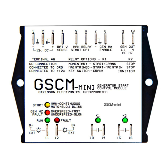
There are 3 program options based on the generator The GSCM-mini-P has six indication LEDs. make for the GSCM-mini-P’s two relay contacts to be The Start LED blinks every 5 seconds to indicate it is ready for : Champion, Cummins/Onan &... -
Page 4: Option 1 Diagram
GSCM-mini-P Wiring Diagram www.atkinsonelectronics.com Circuit Board Division 800.261.3602 Revised 02/21... - Page 5 45Hz (terminals 9 & 10). 4. If the generator starts but shuts down after a few seconds due to a fuel problem, etc., the GSCM-mini-P exits the run mode, energizing the K2 relay for 1 second, then enters a 60 second delay period blinking the yellow start LED rapidly, then returns to “ready”...
- Page 6 15 seconds and repeats the starting routine. 6. If the generator fails to start after the second round of three attempts the GSCM-mini-P turns on its red fault LED and the GSCM-mini enters the Maximum crank lockout condition and the Generator Hz LED does a double blink.
- Page 7 LED. 5. If the generator fails to start after 6 starting attempts, the GSCM-mini-P turns on its red fault LED and the GSCM- mini enters the Maximum crank lockout condition and the Generator Hz LED does a double blink. This lockout condition remains until the GSCM-mini is reset by removing power from terminal 2, waiting 5 seconds and reconnecting power.
-
Page 8: Manual Off Auto Switch Options
GSCM-mini 60Hz Manual Off Auto Switch Options The manual start signal is created by connecting terminal 5 (manual start) to terminal 3 (B+12VDC) through a power/reset switch. It may also be generated by an Outback Inverter using the AUX+/- connections on the remote terminal block. The Outback provides a switched +12VDC signal for the GSCM-mini 60Hzs manual start input. -
Page 9: Automatic Starting For Battery Charging
4. The GSCM-mini-P will shut down the generator when it has run in auto-start battery charging mode for 6 hours and has not charge the battery above the shutdown threshold. The GSCM-mini-P then returns to ready mode looking for a start command. -
Page 10: Generator Emergency Shutdown
LED Description and Meanings Start: One blink every 5 seconds = ready mode, looking for a start signal One blink every 2.5 seconds = auto start mode operation One blink every other second= auto start/stop period Continuous = manual start signal received Fast blink = 60 second delay after start signal removed before generator started Generator Hz Shutdown Fast blink = over speed condition... - Page 11 The GSCM-mini-P’s terminal #6 is not connected. Terminal #3 (+12vdc) is connected to Samles’s normally open relay contact, and the common contact wires back to terminal #5 on the GSCM-mini-P. The generators AC output is wired to terminals # 9 &...
- Page 12 The GSCM-mini-P’s terminal #6 is connected to terminal #3 (+12vdc) and to Samlex’s normally open relay contact, and the common contact wires back to terminal #5 on the GSCM-mini-P. The generators AC output is wired to terminals # 9 & 10 providing the run feedback signal.
- Page 13 The GSCM-mini-P’s terminal #6 is connected to terminal #3 (+12vdc) and to Samlexs’s normally open relay contact, and the common contact wires back to terminal #5 on the GSCM-mini-P. The generators DC output is wired to terminals # 7 & 8 providing the run feedback signal.
- Page 14 The GSCM-mini-P’s terminal #6 is connected to terminal #3 (+12vdc) and to Samlex’s normally open relay contact, and the common contact wires back to terminal #5 on the GSCM-mini-P. The generators AC output is wired to terminals # 9 & 10 providing the run feedback signal.
- Page 15 GSCM-mini-P’s manual start input. Outback’s AUX- wires to terminal #7and AUX+ wires to terminal #5 on the GSCM-mini-P. The generators AC output is wired to terminals # 9 & 10 providing the run feedback signal. An optional Battery tender/charger is not needed for this option.
- Page 16 The GSCM-mini-P’s terminal #6 is connected to terminal #3 (+12vdc) and to Samlex’s normally open relay contact, and the common contact wires back to terminal #5 on the GSCM-mini-P. The generators DC output is wired to terminals # 7 & 8 providing the run feedback signal.
- Page 17 The GSCM-mini-P’s K1 relay contact wire in parallel with the generators Start/Stop push button. The mini-P’s K2 relay contact wires to a control relay that bypasses the generators power switch. The GSCM-mini-P’s terminal 15 wires to one side of the relay coil (85) the other side of the coil (86) connects to the normally open contact (87) and to the white wire that connects to the power switch and the starter motor.
- Page 18 The Customer's sole and exclusive remedy and the limit of Atkinson Electronics, Inc.'s liability for any loss whatsoever, shall not exceed the purchase price paid by the Customer for the product to which a claim is made.
Need help?
Do you have a question about the GSCM-mini-P and is the answer not in the manual?
Questions and answers