
Related Manuals for Atkinson Electronics GSCM


Summary of Contents for Atkinson Electronics GSCM
- Page 1 Generator Start Control Module Part# GSCM Rev C. Code Version: 5.13 ATKINSON ELECTRONICS, INC. 14 West Vine Street · Murray, Utah 84107...
-
Page 2: Table Of Contents
Code Version Update Changes LEDs are flashed to indicate the cause of the shutdown. GSCM Rev. C set up adjustments is now accomplished Manually resetting, the GSCM removes the lockout and with three push buttons: Change/ store, menu up and allows the generator to restart if called. -
Page 3: Operations
Operation Specifications The GSCM is powered by 12 to 24VDC from a battery SIZE: 5.5”L x 3.3”W x 1.5”H bank and will start generators for 12 to 48V systems. For 48V systems the GSCM must be powered by a 24V... -
Page 4: Gscm Wiring Diagram
GSCM Wiring Diagram www.atkinsonelectronics.com Circuit Board Division 800.261.3602 Revised 09/18... -
Page 5: Gscm Starting Sequence
GSCM Starting Sequence The GSCM indicates that it is ready to receive a start signal by blinking the start LED once every 5 seconds. The GSCM is started by shorting terminal 5 to ground (terminal 6) for manual start mode. The module may also start in automatic mode based on a battery voltage, See AUTOMATIC STARTING FOR BATTERY CHARGING section, or a 30 day exercise cycle. -
Page 6: Gscm Shutdown Conditions
15. The GSCM will start a 30day exercise period of up to 1 hour run time, if the exercise time is set above 0 minutes (above 0V @ the test point, when in setup mode) and a reset has been applied for 30 seconds. If a DC voltage greater than 6V is connected to either terminal 11 or 12 the GSCM will exercise the generator with load or without load (energizing K5 load relay). -
Page 7: Automatic Starting For Battery Charging
Automatic Starting for Battery Charging or from Pressure Switch, Etc. The GSCM monitors a battery voltage of 0 to 60VDC on battery voltage sense terminal 4. This mode is disabled if the voltage on terminal 4 is less than 6V, (no connection) or both the cut-in or cut-out voltage adjustment has been set to 5V. -
Page 8: Gscm Reset Conditions
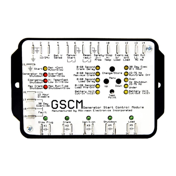
GSCM Initialization and Adjustment 1. Powering up the GSCM with a jumper placed on reset terminals 7 and 8 will cause it to enter the adjustment mode. When the crank delay LED is lit the GSCM will accept timing modifications to any of the factory settings. See diagram in GSCM ADJUSTMENT CHART, which describes each adjustment LED and the setting that it refers to. -
Page 9: Led Description And What They Mean
6. Resetting the GSCM for 60 seconds by shorting terminals 7 and 8 while in the ready mode forces the GSCM back to the original factory default settings, as it came out of the box. The adjustment LEDs blink once in sequence to indicate a return to default settings. -
Page 10: Gscm Adjustment Charts
GSCM Adjustment Chart Adjustment Formulas 0 - 60 Second/min/Vbat TPV = (Desired Value ÷ 60) x 5 Example: 11.5V Bat = 0.96V (TPV) 0 – 120 (Sec) TPV = (Desired Sec ÷ 120) x 5 55Hz = 3.33V (TPV) 15 – 75 Hz TPV = {(Desired Hz - 15) ÷... -
Page 11: Electric Start Generators Control Box
This application matches most high speed or portable generator sets that have an electric starter and some type of starter control. These generators should have the ignition switch left in the on position. The start commands usually come through the GSCM connected to the remote start terminals. - Page 12 The low speed gas/ propane generators also wire the same as in application 2. However, the installer should determine ignition type and oil and high temperature safety shutdown wiring. The GSCM is looking for oil and high temperature safety switches that short to ground on a low oil pressure or high temperature condition.
-
Page 13: Diesel Generators
Diesel Generators The diesel generator is started by the GSCM in either automatic or manual mode. A field installed relay that will handle the glow plug current is needed if not already installed on the engine. A fuel control solenoid is connected to the K3 (ignition) relay terminals. -
Page 14: Fuel Powered Pump
GSCM K5 (load transfer) relay starts the air conditioner after the generator is running. When the thermostat is satisfied, it opens the start signal to the GSCM. The air conditioner is instantly turned off by the K5 (load transfer) relay, however, the generator continues to run during the cool down cycle for the period of time selected. -
Page 15: Outback Inverter Auto Generator Start
May 2004 will still require a 12VDC relay to interface with the Outback Inverter. A remote generator start switch or manual off auto switch may still be connected to the GSCM along with the Outback Inverter, but it needs to be connected to the GSCM power terminal as shown in the optional remote switch diagram. -
Page 16: Limited Warranty
The Customer's sole and exclusive remedy and the limit of Atkinson Electronics, Inc.'s liability for any loss whatsoever, shall not exceed the purchase price paid by the Customer for the product to which a claim is made.
Need help?
Do you have a question about the GSCM and is the answer not in the manual?
Questions and answers