Table of Contents
Advertisement
Quick Links
Advertisement
Table of Contents

Related Manuals for Victron energy VE.Bus BMS


Summary of Contents for Victron energy VE.Bus BMS
- Page 1 Manual VE.Bus BMS...
-
Page 3: General Description
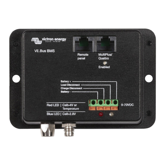
Operating voltage range of the BMS: 9 to 70 V DC. Communicates with all VE.Bus products The VE.Bus BMS connects to a MultiPlus, Quattro or Phoenix inverter with a standard RJ45 UTP cable. Products without VE.Bus can be controlled as shown below: Load Disconnect The Load Disconnect output is normally high and becomes free floating in case of imminent cell under voltage. - Page 4 A Battery Protect will disconnect the load when: input voltage (= battery voltage) has decreased below a preset value, or when the remote on/off terminal is pulled low. The VE.Bus BMS can be used to control the remote on/off terminal (Non inverting remote on-off cable needed).
-
Page 5: Installation
4. Installation 4.1 AC Detector for MultiPlus and Quattro The purpose of the AC Detector is to restart the MultiPlus or Quattro when AC supply becomes available, in case it has been switched off by the BMS due to low cell voltage (so that it can recharge the battery). Note 1: The AC Detector is not needed in case of an inverter. - Page 6 Connect the VE.Bus BMS to the AC Detector with a UTP cable (not included). If a VE.Bus control panel is used: connect to the Remote If a VE.Bus control panel is used: connect to the Remote Panel socket of the VE.Bus BMS. Figure 4: VE.Bus connections 4.2 Wire the system...
-
Page 7: System Examples
4.3. Powering up In case of a DC only system: connect the battery plus. The system is now ready for use. In case of a system with Multis, Quattros or inverters with VE.Bus: 4.3.1. After completion of the installation, disconnect the BMS from the VE.Bus and replace by a Victron Interface MK2 and a computer. - Page 8 Figure 7: System for a boat or vehicle with inverter/charger (DC fuses not shown) Note: the BMS is connected to the battery minus by the UTP cable between the BMS and the inverter/charger. Therefore, in order to prevent ground loops, do not wire the BMS minus connector. Figure 8: System for a boat or vehicle with a three phase inverter/charger configuration (DC fuses not shown) Note 1: the AC Detector is installed only in the leader.
-
Page 9: Specification
6. Dimensions 7. Specification VE.Bus BMS Input voltage range 9 – 70 VDC Current draw, normal operation 10 mA (excluding Load Disconnect current) Current draw, low cell voltage 2 mA Normally high (supply voltage – 1 V) Load Disconnect output... - Page 11 Appendix: Loads which can be controlled directly by the Load Disconnect output of the BMS Inverters: Phoenix 12/800 Phoenix 24/800 Phoenix 12/1200 Phoenix 24/1200 Phoenix 48/800 Phoenix 48/1200 DC-DC converters: Orion 12/24-20 Orion 24/12-25 Orion 24/12-40 Orion 24/12-70 Loads for which a Inverting remote on-off cable is needed (also known as the MPPT 70/15 to inverter remote on-off cable, article number ASS030550100)
- Page 13 Serial number: Version : 01 Date : 14 June 2013 Victron Energy B.V. De Paal 35 | 1351 JG Almere PO Box 50016 | 1305 AA Almere | The Netherlands General phone +31 (0)36 535 97 00 Customer support desk...
Need help?
Do you have a question about the VE.Bus BMS and is the answer not in the manual?
Questions and answers