Advertisement
Quick Links
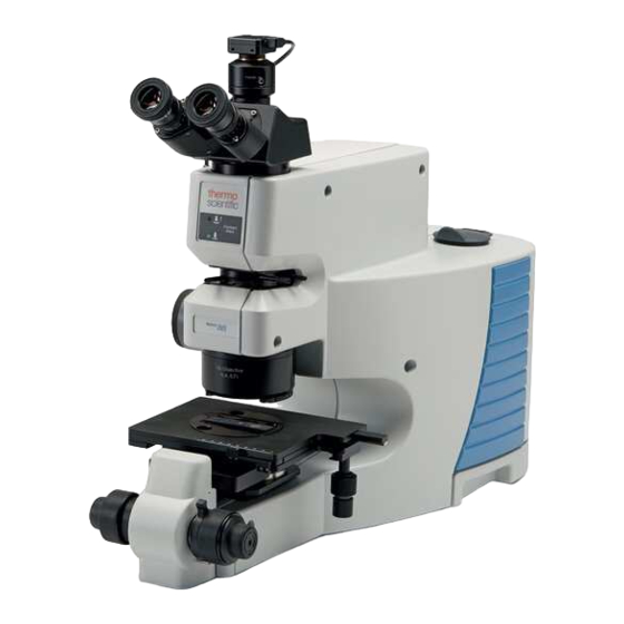
Title: Installing the Nicolet iN5™ Microscope
Revision: 03
Procedure: Install-001
ECCN: EAR99
Part number: 912A0895 and 912A0922 with any of the follow ing viewing options:
840-287200
840-293700
840-287100
Part description: Nicolet iN5 IR Microscope w ith MCTA and Nicolet iN5 IR Microscope with DTGS w ith any of the
follow ing viewing options:
840-287200 – Camera only
840-293700 – Binoc only
840-287100 – Trinoc and Camera
Functional description: Point and Shoot Infrared Microscope compatible w ith a Nicolet iS10 or iS50.
Problems associated with this assembly: Alignment, Detector evacuation, Optical contamination, Wear, Damage
Tools required:
Scissors
Box cutter
3-1 Tool
Small flat blade screwdriver
Medium Flat blade screwdriver
3/16 inch balldriver
5/16 inch T-wrench or L-wrench
5/32 inch ball driver
3mm Balldriver
Tw o- 3/32 inch balldriver
5/16 inch balldriver
Tw o- 5/64 inch balldrivers
0.05 inch balldriver
Needle nose pliers
Pow der-free gloves
Micrometer/S78 1MM /.01MM Reflected (Calibration slide) – Service rep needs to provide/not included w ith iN5
LN2 and proper safety equipment (for MCTA configurations)
Estim ated time required: 6-8 Hours depending on configuration
Notes:
1.
This procedure can be used to install both New Nicolet iN5 microscopes and aftermarket installations.
2.
Refer to page 3 for software and firmware requirements.
This document contains confidential or proprietary informat ion of Thermo Fisher Scientific. Neither this document nor
the information therein is to be reproduced, distributed, used or disclosed, either in whole o r in part, except as
1/4/2018
specifically authorized by Thermo Fisher Scientific.
Nicolet iN5
Page 1 of 84
Advertisement

Related Manuals for ThermoFisher Scientific Nicolet iN5


Summary of Contents for ThermoFisher Scientific Nicolet iN5
- Page 1 Part number: 912A0895 and 912A0922 with any of the follow ing viewing options: 840-287200 840-293700 840-287100 Part description: Nicolet iN5 IR Microscope w ith MCTA and Nicolet iN5 IR Microscope with DTGS w ith any of the follow ing viewing options: 840-287200 – Camera only 840-293700 – Binoc only 840-287100 –...
- Page 2 Installing the Nicolet iN5 Microscope Notes Release. Made corrections per customer audit. Updated note in step 27 to test aperture position repeatability. Removed gain setting from step 28c. • Added firmware and software requirements to page 3. • Added new step and comment regarding firmware to step 2.
- Page 3 Installing the Nicolet iN5 Microscope Important: Prior to performing this procedure, you must read the Nicolet iN5 Microscope Site and Safety Guide. If you do not have the Safety Guide, it is available for download from the Knowledge Base. If you do not have access to the Knowledge Base, email international support to request access at Support.Madison@thermofisher.com.
- Page 4 The top tray contains software, sensitive optical components and other parts for the Nicolet iN5. Use caution when removing the tray. b. Remove all parts from the top tray and set the parts aside.
- Page 5 Installing the Nicolet iN5 Microscope c. Remove the secondary tray. The secondary tray contains accessories. d. Remove the thermos and accessory cases from the tray and set aside. e. Carefully lift the enclosure box straight up to release it from the bottom tray and set aside.
- Page 6 Installing the Nicolet iN5 Microscope f. Remove the white foam block from the top of the iN5 and set aside. g. Carefully lift the iN5 from the lower tray and set on a flat, sturdy surface. h. Remove the plastic bag from the iN5.
- Page 7 Installing the Nicolet iN5 Microscope b. Remove the blue tape from the binoc/trinocular dovemount shown below and the blue tape and red cap from purge extension tube (not shown) and discard. c. Check the iN5 for damage. If damage is apparent, stop here and contact the factory otherwise continue with step 5d.
- Page 8 Installing the Nicolet iN5 Microscope b. Lift straight-up on the accessory to remove it from the iS10 and set the accessory aside. c. Remove the accessory tray by pulling straight-out from the front of the system and set the tray aside.
- Page 9 Installing the Nicolet iN5 Microscope e. Using the Phillips tip, loosen the 2 captive cover screws on the front corners of the iS10 and at each corner on the back of the iS10. Loosen two front captive screws Loosen two back captive screws f.
- Page 10 Installing the Nicolet iN5 Microscope 7. Unpack the iN5 interface bracket and connect to the iS10. a. Remove the interface bracket with screws from the plastic bag. b. Remove the tape from the arm of the bracket to release the bag of 4- mounting screws;...
- Page 11 Installing the Nicolet iN5 Microscope e. Slide the interface toward the iS10 until the end of the channel is fully engaged with the locator pin. f. Using a needle nose plier, remove the purge plugs from the iS10 at the following locations, see below and on the following page.
- Page 12 Installing the Nicolet iN5 Microscope Remove plug from main bench at location shown g. Secure the interface. Using a 3/16 inch balldriver and the mounting screws set aside in step 7c, loosely thread all 4 screws into the locations shown below and then tighten all 4 screws to secure the interface to the iS10.
- Page 13 Installing the Nicolet iN5 Microscope Install screw in main bench at location shown h. If installing a new iS10 motorized external beam mirror on an existing iS10, install it now otherwise continue with step 7i. i. Reinstall the iS10 main cover, accessory tray and sample accessory by reversing steps 6a-6f and then continue with step 10.
- Page 14 Installing the Nicolet iN5 Microscope 8. Prepare the Nicolet iS50. a. Release the iS50 sample compartment cover by opening the cover and turning the latch approximately 45° clock-wise. Locked Unlocked b. Lift straight-up on the cover to remove it from the iS50 and set the cover aside.
- Page 15 Installing the Nicolet iN5 Microscope c. Using a medium flat-blade screw driver, remove the four screws from the sample compartment plate. Then remove the sample compartment plate from the iS50 and set the plate and screws aside. Remove four screws Remove sample compartment plate This document contains confidential or proprietary informat ion of Thermo Fisher Scientific.
- Page 16 Installing the Nicolet iN5 Microscope d. Using a medium flat-blade screwdriver, loosen the four latches on the iS50 main cover, lift straight up to remove the cover and set the cover aside. Loosen four latches and remove the cover 9. Unpack the iN5 interface bracket and connect to the iS50.
- Page 17 Installing the Nicolet iN5 Microscope c. Carefully open the bag of mounting screws and set the screws aside. d. Connect the iS50 touch point extension cable to the interface. e. Place the interface next to the right-side of the iS50. Align the channel in the interface to the locator pin under the iS50 baseplate located left of center.
- Page 18 Installing the Nicolet iN5 Microscope f. Slide the interface toward the iS50 until the end of the channel is fully engaged with the locator pin. g. Wearing powder-free gloves gently move the passport mirror to the right side to access the purge screw.
- Page 19 Installing the Nicolet iN5 Microscope h. Using a 5/32 inch balldriver, remove the two purge screws from the iS50 at the following locations. Set all purge screws with the customer parts. Remove purge screw from sample compartment Remove purge screw that is accessible...
- Page 20 Installing the Nicolet iN5 Microscope i. Secure the interface. Using a 5/32 inch balldriver and the mounting screws set aside in step 9c, loosely thread the 2 screws into the locations shown below and then tighten the screws to secure the interface to the iS50.
- Page 21 Installing the Nicolet iN5 Microscope 10. Connect the iN5. a. Slide the purge sleeve back toward the iN5. b. Set the interface latch. Using a 5/16 inch T-handle or L-wrench, turn the screw in the interface bracket completely clockwise to extend the latch and then turn completely counter-clock-wise to retract the latch assuring it is set to engage with the locator pin under iN5 baseplate.
- Page 22 Installing the Nicolet iN5 Microscope c. Slide the iN5 up to the iS10 or iS50 interface bracket so the holes in the left side of the iN5 align with the locator pins on the interface bracket and then continue to slide the iN5 toward the spectrometer so the iN5 engages with the locator pins.
- Page 23 Installing the Nicolet iN5 Microscope d. Using a 5/16 inch T-handle or L-wrench turn the screw in the interface clockwise until it stops. The latch should engage with the locator pin under the iN5 and lock it into position. If not, reset the latch and then reconnect.
- Page 24 Installing the Nicolet iN5 Microscope f. Slide the purge sleeve to the left so it securely engages with the rubber gasket around the hole or KBr window in the spectrometer cover. 11. Remove the right-side cover from the iN5. Using a 5/32 inch balldriver, loosen the seven captive screws to release the cover.
- Page 25 Installing the Nicolet iN5 Microscope 12. Prepare the iN5 components. Remove the packing materials from all iN5 components removed from both trays including the red cap from the condenser. Depending on the iN5 configuration ordered this may include the binocular viewer;...
- Page 26 Installing the Nicolet iN5 Microscope 14. Prepare the detector. a. If the iN5 is connected to an iS50 spectrometer, change the detector switch settings (the iN5 is tested on an iS10 at the factory and the detector switch settings are addressed for an iS10 spectrometer when shipped).
- Page 27 Installing the Nicolet iN5 Microscope 15. Install the iN5 components. a. Insert a 3/32 inch balldriver into the set-screw on the right-side of the viewer dovemount and turn counter-clockwise to back the screw out enough to install the binocular or trinocular viewer.
- Page 28 Installing the Nicolet iN5 Microscope c. Install the eyepieces if applicable otherwise continue with step 15d. The eyepiece with reticle should be inserted in the right receptacle. Eyepiece with reticle d. Using the knobs on the sides of z stage assembly, turn the knobs counter-clockwise (toward you) to raise the z stage platform all the way up, until it stops.
- Page 29 Installing the Nicolet iN5 Microscope ii. Insert the condenser into the condenser rack from the right side of the iN5 so the threaded hole in the condenser is facing the thumbscrew on left side of the rack. Thumbscrew Install condenser from the right-side Align hole in condenser to thumbscrew This document contains confidential or proprietary informat ion of Thermo Fisher Scientific.
- Page 30 Installing the Nicolet iN5 Microscope iii. Ensure the hole and the tip of the screw line up and then slide the condenser towards the thumbscrew until it stops and hold the condenser securely. Then, gently push the thumbscrew into threaded hole to engage the condenser and then snug the screw so the condenser is secure.
- Page 31 Installing the Nicolet iN5 Microscope f. Install the X-Y stage. i. Using the z stage focus knobs, turn the knobs clockwise (away from you) to lower the z stage so the z stage dovemount is just above the condenser. Dovemount slightly above condenser ii.
- Page 32 Installing the Nicolet iN5 Microscope iii. Rotate the stage as necessary to square it to the iN5 then turn the thumbscrew clockwise to secure the stage. Thumbscrew Square the stage to iN5 then lock in place iv. Install the sample holder and rotate until it “clicks” into place.
- Page 33 Installing the Nicolet iN5 Microscope v. If you have an iN5 viewer with eyepieces, insert a gold or aluminum slide into the sample holder then continue with step 16. If you have an iN5 viewer with a camera only, continue with step 16.
- Page 34 Installing the Nicolet iN5 Microscope c. Connect the 15 pin accessory cable between the spectrometer and the iN5 Accessory connector on the I/O panel and tighten the thumbscrews. Note The accessory cable must be connected to the iS50 OBC right-side accessory port;...
- Page 35 18. Turn the iN5 power ON. 19. Open MicroView and configure the system. a. From the Microscope drop-down menu select Nicolet iN5; set the X-Y Stage to None and click Save. b. From the Camera drop-down menu select StUSBCam and click OK. If you do not have a viewer with a camera installed continue with step 20.
- Page 36 Installing the Nicolet iN5 Microscope c. From the Microscope drop-down menu select System Configuration and if necessary, set the camera resolution to 1280 x 960. d. Select Video Calibration. i. From the Brief Description drop-down menu select Factory iN5 and click Set Current.
- Page 37 Installing the Nicolet iN5 Microscope 20. If you have an iN5 viewer with eyepieces, switch the iN5 to reflection mode by moving the knob on the left side of the iN5. If you have an iN5 viewer with a camera only, switch the iN5 to transmission mode by moving the knob on the left side of the iN5.
- Page 38 Installing the Nicolet iN5 Microscope 23. Adjust the eyepieces. a. Use the z stage focus knobs to raise the z stage and bring the gold or aluminum slide into focus; adjust the illumination as necessary. If you cannot focus on the clean gold or aluminum slide, move stage Y axis back so the edge of the slide is centered under the objective then focus on the edge of the slide.
- Page 39 Installing the Nicolet iN5 Microscope d. While looking through the right eyepiece with your right eye, rotate the entire right eyepiece to orient the cross hairs as shown. e. While looking through the left eyepiece with your left eye, turn the eyepiece until the slide is in focus.
- Page 40 Installing the Nicolet iN5 Microscope 24. Focus the condenser through the eyepieces. a. While looking through the eyepieces, turn the condenser knob on the lower left side of the iN5 approximately ¾-1 turn counter clockwise to raise the condenser; the field of view (FOV) should be illuminated.
- Page 41 Installing the Nicolet iN5 Microscope c. Using two 5/64 inch balldrivers, adjust the condenser X-Y alignment screws to center the target image and then continue with step 27. Adjust condenser X-Y alignment 25. If you cannot find the target image, slowly raise or lower the condenser until you see a dark spot as depicted below.
- Page 42 Installing the Nicolet iN5 Microscope Using two 5/64 inch balldrivers, adjust the condenser X-Y alignment screws to center the dark spot, repeat steps 24a-b and then continue with step 27. Adjust condenser X-Y alignment Center dark spot This document contains confidential or proprietary informat ion of Thermo Fisher Scientific. Neither this document nor the information therein is to be reproduced, distributed, used or disclosed, either in whole o r in part, except as specifically authorized by Thermo Fisher Scientific.
- Page 43 Installing the Nicolet iN5 Microscope 26. If a camera only is installed, focus the condenser using MicroView. a. While looking at the video screen in MicroView, turn the condenser knob on the lower left side of the iN5 approximately ¾ turn counter clockwise to raise the condenser.
- Page 44 Installing the Nicolet iN5 Microscope b. Focus condenser and adjust X-Y position. Ensure the condenser is focused by fine tuning the condenser knob if necessary using the dark corner/corners as a reference. Out of focus In focus If necessary, using two 5/64 inch balldrivers, move the condenser in the direction necessary to view two dark corners if only one is visible.
- Page 45 Installing the Nicolet iN5 Microscope 27. Insert the 100µm fixed aperture. The aperture should be installed with the text properly orientated and facing out (toward you). Note The upper plate of the slot is flexible so the aperture can easily be inserted and removed.
- Page 46 Installing the Nicolet iN5 Microscope When viewing the sample aperture image in Microview for both camera only or trinoc/camera viewer options, the sample aperture image should be centered on the red crosshair, if not, the aperture center will be defined using Video Calibration later in this procedure.
- Page 47 Installing the Nicolet iN5 Microscope Note Only the default files that correspond to the detector installed will be available on a new system. 29. Tune the input mirror. a. Select the bench tab and ensure the Sample Compartment = Right µScope, % T.
- Page 48 Installing the Nicolet iN5 Microscope c. Using a 5/64 inch balldriver, adjust the two opposing screws on the input mirror for best MAX interferogram peak. MCT should be ~7 volts MAX DTGS should be 2.5 volts MAX or greater d. If the Max peak is between 7-7.5 volts continue with step 30 otherwise continue with step 29e.
- Page 49 Installing the Nicolet iN5 Microscope If you have an iS50 spectrometer and the software prompts to change to Smart Mode, select Yes then select Beampath = µScope, right. f. If you have an iS10 spectrometer, ensure the detector Mode = Legacy.
- Page 50 Installing the Nicolet iN5 Microscope g. While viewing the interferogram, change the Gain DAC 1X as appropriate to increase the interferogram MAX peak to ~7 volts. h. Lower the condenser stage. i. Close BDiag. 30. Tune the sluice (reflection) mirror.
- Page 51 Installing the Nicolet iN5 Microscope b. Insert a gold or aluminum slide in the sample holder and focus on the mirrored slide. If using an aluminum slide, ensure the aluminum side in facing up and not the glass side or the signal will be significantly reduced and the single beam distorted.
- Page 52 Installing the Nicolet iN5 Microscope c. Using a 5/64 inch balldriver, adjust the two opposing screws on the sluice mirror for best MAX interferogram peak. MCT MAX peak should be ~1/2 the throughput of transmission mode DTGS MAX peak should be ~1/2 the throughput of transmission mode...
- Page 53 Installing the Nicolet iN5 Microscope 31. Lower the z stage. 32. Remove the sample holder and slide. Remove the slide from the sample holder and then remove the sample holder and set aside. 33. Remove the X-Y manual stage and set aside.
- Page 54 Installing the Nicolet iN5 Microscope 37. Remove the 100µm fixed sample aperture and set aside. 38. Reinstall the X-Y manual stage and sample holder. 39. Adjust the binocular viewer. If a camera only is installed, continue with step 40. a. Switch the microscope to reflection mode.
- Page 55 Installing the Nicolet iN5 Microscope d. Level the calibration scale. The scale should be level as viewed through the eyepieces. i. If the scale is level and you have a binocular viewer only, continue with step 45. ii. If the scale is level and you have a camera installed, continue with step 40.
- Page 56 Installing the Nicolet iN5 Microscope 40. Adjust the camera rotation. a. If not already in reflection mode, switch the microscope to reflection mode. Reflection mode b. If not already installed, install the calibration slide into the sample holder so the text on the slide is upside down when installed.
- Page 57 Installing the Nicolet iN5 Microscope d. Assess the camera rotation. Assess the levelness of the scale in the Microview. Scale tilted Scale le vel i. If the scale is level continue with step 41. ii. If the scale is not level (tilted) complete step 40e and then continue with step 41.
- Page 58 Installing the Nicolet iN5 Microscope 41. Focus the camera. While viewing the calibration scale in Microview, turn the camera focus ring clockwise or counterclockwise for best focus. Note The camera is focused to match the focus at the stage through the eyepieces if a binocular viewer is also installed.
- Page 59 Installing the Nicolet iN5 Microscope 42. Set the video properties. a. Place a flat-white business card, print-side down on the calibration slide and raise the z stage to focus on the fibers. Adjust the illumination as necessary. b. From the Microscope drop-down menu select System Configuration and then select Video Source.
- Page 60 Installing the Nicolet iN5 Microscope Click the Interpolation Mirror tab and set the Mirror Mode to Off (Normal). d. Select the White Balance tab This document contains confidential or proprietary informat ion of Thermo Fisher Scientific. Neither this document nor the information therein is to be reproduced, distributed, used or disclosed, either in whole o r in part, except as specifically authorized by Thermo Fisher Scientific.
- Page 61 Installing the Nicolet iN5 Microscope e. Set white balance. i. If the White Balance mode is Full auto, change it to Manual and click Apply. ii. If the White Balance mode is Manual, change to Full auto and then back to Manual and then click Apply.
- Page 62 Installing the Nicolet iN5 Microscope i. If there is a Default Registry file available, click on the word Default to highlight it. Check the Default load box and click Save. Answer Yes to Would you like to replace the setting? Then, click OK to exit the window.
- Page 63 Installing the Nicolet iN5 Microscope h. Click OK to exit the Video Source window. i. Remove only the business card from the sample stage. 43. If the iN5 has a camera and a binocular viewer installed OR a camera only installed and the sample aperture image was not centered on the crosshair in Microview in step 27, continue with step 44.
- Page 64 Installing the Nicolet iN5 Microscope i. If you have a camera only installed, adjust the z stage to focus on the calibration scale. Then move the X-Y stage to center the edge of the 50µm tic mark so it is positioned at the exact center of the gray crosshair in the center of the video calibration window.
- Page 65 Installing the Nicolet iN5 Microscope d. Define the video field of view center. i. If you have a binocular viewer and camera installed, crop the field of view on both the X and Y axis slightly (indicated by the white dashed lines) and then move the gray calibration crosshair so it is exactly on the end of the 50µm tic mark in the video...
- Page 66 Installing the Nicolet iN5 Microscope f. Remove the fixed 100µm aperture and set it aside. g. Move distance marker 1 to the top of the furthest tic mark on the left- side of the cropped window (tic mark 30 in the illustration). Move distance marker 2 to the top of the farthest tic mark on the right-side of the cropped window (tic mark 70 in the illustration).
- Page 67 Installing the Nicolet iN5 Microscope i. From the brief description drop-down menu select 10X and click Set to Current. Click close to exit the window. j. Remove the calibration slide from the sample holder. 45. Align the Ge Tip ATR; if you do not have a Ge Tip ATR, continue with step 46.
- Page 68 Installing the Nicolet iN5 Microscope c. Insert the 100µm fixed sample aperture ensuring it is properly seated and centered in either the binocular viewer OR on the red crosshair in the Microview window. Refocus on the aperture image if necessary.
- Page 69 Installing the Nicolet iN5 Microscope Select the Collect tab, change the following parameters and click OK. g. From the Collect drop-down menu select collect background and then click Start Collection. You can choose either yes or no to add the background to the current window.
- Page 70 Installing the Nicolet iN5 Microscope j. Using a .05 inch balldriver, loosen the rotational [focus] screw on the ATR slide enough to rotate the crystal. k. From the Collect drop-down menu select collect sample, select the default spectrum title or enter a title, click OK and leave the sample collection in preview mode.
- Page 71 Installing the Nicolet iN5 Microscope m. Start the sample collection to complete the rotational alignment and save the results if applicable. n. Remove the sample holder with slide from the X-Y stage and set aside. o. Remove the 100µm fixed aperture and set aside.
- Page 72 Installing the Nicolet iN5 Microscope s. Install the Contact Alert plate on to the X-Y stage ensuring it “clicks” in place. Connect the contact alert cable to the side of the iN5. t. Ensure that no pressure was applied to the contact alert due to the taping of the slide (green/red indicator LED’s should be OFF).
- Page 73 Installing the Nicolet iN5 Microscope v. Lower the z stage to make clearance for the tip ATR and then push the ATR all the way into the objective until it “clicks” into place. w. Using the z stage focus knobs, raise the z stage until the ATR is close...
- Page 74 Installing the Nicolet iN5 Microscope aa. Using two, 5/64 inch balldrivers, make adjustments to the ATR crystal to center it in the reticle square or the crosshair of Microview. Note the adjustments move the crystal diagonally in expected directions. bb.Repeat steps 45u-45aa until the footprint is centered.
- Page 75 Installing the Nicolet iN5 Microscope 48. Configure the iS50/iN5 interface touch point; if you do not have an iS50 interface, continue with step 49. a. From the Omnic window ensure the microscope touch point icon is selected and then click the settings icon.
- Page 76 Installing the Nicolet iN5 Microscope 49. Switch the iN5 to transmission mode by moving the knob on the left-side of the iN5. Transmission mode 50. Raise the z stage and then focus and center the condenser as necessary. 51. If not already installed, insert the fixed 100µ sample aperture. Ensure the aperture image is centered and focused as viewed through the eyepieces or Microview window.
- Page 77 Installing the Nicolet iN5 Microscope d. Click Performance Test, select the Microscope icon and then click Run Test. Click OK to the iN5 Objective and final format window and click OK to the Prepare the microscope message. This document contains confidential or proprietary informat ion of Thermo Fisher Scientific. Neither this document nor the information therein is to be reproduced, distributed, used or disclosed, either in whole o r in part, except as specifically authorized by Thermo Fisher Scientific.
- Page 78 Installing the Nicolet iN5 Microscope e. Ensure the performance test passes. If it passes, continue with step 53; if it does not pass, contact the factory. MCTA DTGS iN5 Performance Specifications MCTA DTGS Transmission Mode 2200.0-2100.0 cm-1 .070 1.000 Reflection Mode 2200.0-2100.0 cm-1...
- Page 79 Installing the Nicolet iN5 Microscope 53. Switch the iN5 to reflection mode by moving the knob on the left side of the iN5. Reflection mode 54. Install the sample holder with gold or aluminum slide and focus on the slide.
- Page 80 Installing the Nicolet iN5 Microscope f. Ensure the performance test passes. If it passes, continue with step 56; if it does not pass, contact the factory. MCTA DTGS iN5 Performance Specifications MCTA DTGS Transmission Mode 2200.0-2100.0 cm-1 .070 1.000 Reflection Mode 2200.0-2100.0 cm-1...
- Page 81 Installing the Nicolet iN5 Microscope 56. Close diagnostics window. 57. Remove the sample holder and slide. 58. Run ValPro. If you do not have ValPro, continue with step 59. a. Switch the iN5 to transmission mode by moving the knob on the left- side of the iN5.
- Page 82 Installing the Nicolet iN5 Microscope e. Using the X-Y stage knobs, move the stage so the open-hole (transmission background) is centered under the objective. Refer to the illustration in step 58j if necessary. From the OMNIC collect drop-down menu select Experiment Setup, select the Bench tab and click OPEN.
- Page 83 Installing the Nicolet iN5 Microscope j. Select the Nicolet iN5 Microscope MCT-A or DTGS Detector KBr-EP test and then click Qualify. Follow the command prompts to complete the Transmission and Reflection tests. When complete, remove the Validation plate and store in the protective case.
- Page 84 Installing the Nicolet iN5 Microscope n. Remove the 32 Mil sample slide and store in the protective case. 59. If a variable glass or black aperture were ordered, ensure the blades move smoothly by turning the adjustment screws so the blades are fully open and then fully closed.
Need help?
Do you have a question about the Nicolet iN5 and is the answer not in the manual?
Questions and answers