Advertisement
Quick Links
Procedure: Installation
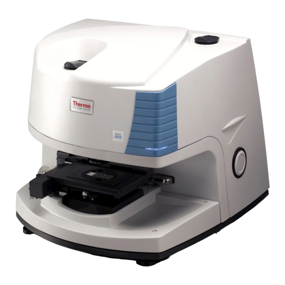
Title: Installing the iN10/iN10MX
Revision: 09
Procedure # Install-001
ECCN: EAR99
Part number: 912A0604/912A0605/912A0804/912A0805
Part description: iN10/iN10MX Integrated Infrared Microscope
Tools required:
Scissor
Short handled medium Phillips screwdriver
Long handled medium Phillips screwdriver
Flat blade screwdriver
5/64" balldriver or L-wrench (array alignment)
Needle nose pliers (iZ10 interface installation)
Pliers (iZ10 installation)
3/16" L-wrench (iZ10 installation)
5/32" balldriver (iZ10 installation)
Laboratory grade powder-free gloves
ATR Crystal alignment procedure
Service test slide
100um Pinhole slide
Estimated time required: Approximately 4 -12 hours depending on
configuration.
Notes: N/A
This document contains confidential or proprietary information of Thermo Fisher Scientific. Neither this
document nor the information therein is to be reproduced, distributed, used or disclosed, either in whole or
in part, except as specifically authorized by Thermo Fisher Scientific.
8/3/2020
iN10/iN10MX
MX
Page 1 of 61
Advertisement

Subscribe to Our Youtube Channel
Related Manuals for ThermoFisher Scientific iN10


Summary of Contents for ThermoFisher Scientific iN10
- Page 1 Title: Installing the iN10/iN10MX Revision: 09 Procedure # Install-001 ECCN: EAR99 Part number: 912A0604/912A0605/912A0804/912A0805 Part description: iN10/iN10MX Integrated Infrared Microscope Tools required: Scissor Short handled medium Phillips screwdriver Long handled medium Phillips screwdriver Flat blade screwdriver ...
- Page 2 Installing the iN10/iN10MX Notes Release. Added step to setting video properties to include turning off all auto gains. Added step to back-up system parameters. Moved running a bench status report to the end of the procedure. Updated picture and procedure to reflect the new AEM mirror flipper shipping restraint.
- Page 3 Important: Prior to performing any replacement procedure, you must read the Nicolet iN10 Safety Guide. If you do not have the Safety Guide, it is available for download from the PSE website. If you do not have access to the PSE website, email international support to request access at Support.Madison@thermofisher.com...
- Page 4 Installing the iN10/iN10MX 1. If your system was ordered with validation certification, complete this installation procedure before performing ValPro. 2. Release bands and unwrap the system. The system is shipped with the main system package and the computer packages wrapped and banded together.
- Page 5 Installing the iN10/iN10MX 4. Open the main system shipping box. Using a scissor, cut and remove the plastic bands that hold the main system box closed. Open the box lid. 5. Remove the upper foam restraint. Inside will be the system enclosed in a desiccated plastic bag and the accessory box.
- Page 6 Installing the iN10/iN10MX 7. Remove the accessory box. 8. Open the Accessory box. 9. Remove the top layer of foam. Set aside the “Open Me First” folder. Unpack the cables, purge hardware, software CD’s, manuals, LN2 thermos (optional), and hardware joystick (optional).
- Page 7 10. Remove the next layer of foam. This will reveal either the manual X-Y stage or motorized X-Y stage package and up to three additional plastic cases. The cases will be the iN10 Toolkit (standard), the slide on ATR kit (optional), and the ValPro Standards (optional). Set the boxes aside and remove the X-Y stage package.
- Page 8 Installing the iN10/iN10MX 14. Remove the plastic bag. Cut and remove the plastic bag and discard the shipping desiccant packages. Carefully remove the bubble wrap from the area between the objective and condenser. 15. Remove shipping tape. Carefully remove the tape that holds the condenser baffle onto the Z stage.
- Page 9 20. Unpack the iZ10 if applicable, if an iZ10 was not ordered, continue with step 21. Remove the iZ10 from its shipping box and set it on the work surface next to the iN10. Remove and discard of any packing materials and then continue with step 21.
- Page 10 5 screws from under the top front of the iN10 and using a long handled screwdriver remove the two screws at the rear base of the iN10 as shown below. Set the screws aside and lift the cover straight up to remove it from the base. Set the cover aside.
- Page 11 Z stage ring and remove the lower cover from the microscope. Set the cover aside. 24.2. Remove the 3 purge plugs from the base plate of the iN10. Using needle nose pliers; grasp and pull up on the purge plugs and remove them from the baseplate.
- Page 12 Installing the iN10/iN10MX 24.3. Remove the AEM flipper shipping restraint. Using a 5/32” balldriver, remove the screw and shipping restraint from the AEM flipper assembly. Store the screw and shipping restraint with the customer items in case the system needs to be moved in the future.
- Page 13 Installing the iN10/iN10MX 24.6. Remove the purge plugs from the iZ10. Using needle nose pliers, remove the 4 purge plugs from the iZ10. There 2 plugs on the left edge as depicted below, 1 in the sample compartment and another in the main compartment approximately center behind the sample compartment wall.
- Page 14 Attach the interface plate to the iN10. Tip the iZ10 up from the right side so the interface plate tips down and align the channel with the pin under the left side of the iN10. Carefully slide the plate under the iN10 until the pin is at the end of travel. 24.9.
- Page 15 Store the plug with the customer items. 24.12. Reinstall the iZ10 cover. 24.13. Reinstall the base cover on the iN10. Using the screws removed in step 24.1; reinstall and secure the base cover. 24.14. Remove the external beam-hole plug from the iN10 main cover.
- Page 16 24.18. Install the purge baffle between the iN10 and iZ10. Squeeze the baffle together and slide between the covers of the iN10 and iZ10 making sure it is positioned around the cover openings and does not interfere with the beam.
- Page 17 Installing the iN10/iN10MX 26. Attach the X-Y stage (either manual or motorized). Using a flat blade screwdriver, turn the quick release knob on the X-Y stage counter-clockwise ~3/4 turn to set the quick release for installation. 26.1. Install the X-Y stage on to Z stage dovetail mount. Slide the back of the stage on to the dovetail mount so the “tabs”...
- Page 18 Attach the power supply. Attach the power cord to the power supply “brick” and then attach the power supply “brick” to the power connector to the electronics module at the rear of the iN10. Plug the power cord into the power outlet. Turn the power on to the iN10.
- Page 19 Installing the iN10/iN10MX 32. Configure the software and iN10. 32.1. Launch Omnic Picta. When the Microscope Configuration screen appears, confirm the Microscope is set to Nicolet iN10, click Save and then close Omnic Picta. Microscope model 32.2. Change the Correction Factor. From C:\My Documents\OMNIC open the OmnicSettings.ini file.
- Page 20 Installing the iN10/iN10MX 32.5. Open the Stage Control screen. From the Window drop down menu choose Stage Control. 32.6. Initialize the X-Y Stage. Click Initialize XY to begin initialization. 32.7. Check the centering of the stage. At the right front corner of the stage, check that all of the stage plates are flush.
- Page 21 Installing the iN10/iN10MX 32.9. Set origin. From the Window drop down menu choose User Configuration. Click Set XY Stage Origin. This resets the home position. 32.10. Verify alignment. Choose the Stage Control tab and click Initialize XY. Assure the X-Y stage plates are flush after initialization.
- Page 22 Installing the iN10/iN10MX 32.13. Lower the Z stage. Click and hold on the Stage Control tab and drag and drop it away from the main diagnostic window. Expand the Stage Control screen to view all controls. Click on the Video tab and click the joystick icon to expand the joystick and use the Z stage focus control to lower the stage so it is approximately 1”...
- Page 23 Installing the iN10/iN10MX Joystick control (icon) Z control Illumination intensity Card in focus This document contains confidential or proprietary information of Thermo Fisher Scientific. Neither this document nor the information therein is to be reproduced, distributed, used or disclosed, either in whole or in part, except as specifically authorized by Thermo Fisher Scientific.
- Page 24 Installing the iN10/iN10MX 32.15. Set video properties. Click the Video Options icon at the lower right side of the video screen to view the video properties and click Advanced Properties. Video options This document contains confidential or proprietary information of Thermo Fisher Scientific. Neither this document nor the information therein is to be reproduced, distributed, used or disclosed, either in whole or in part, except as specifically authorized by Thermo Fisher Scientific.
- Page 25 Installing the iN10/iN10MX 32.15.1 Turn off all Auto (gains) and then select Advanced. If any Auto (Gain) checkbox is checked, uncheck all boxes to turn auto gain off and then click Advanced. Select the Interpolation/Mirror tab, click the Mirror Mode drop down menu, and choose Horizontal.
- Page 26 Installing the iN10/iN10MX 32.15.2 Set the White Balance. Select the White Balance tab and from the White Balance mode drop down menu change from Manual to Full auto. This will automatically adjust the white balance. When complete, set the mode back to Manual.
- Page 27 Installing the iN10/iN10MX 32.15.3 Save the video properties. Click the Load/Save (1) tab and choose Save As (2). When the dialog box opens; type in Default (3) and choose OK (4). Default will appear in the white screen to the left. Click on Default (5) to highlight (select) and then check the Default Load (6) box below the white screen.
- Page 28 33.1.1. Close DDiag. Close all individual windows and then close DDiag. 33.1.2. Turn the power off to the iN10. 33.1.3. Unpack the hardware joystick. This document contains confidential or proprietary information of Thermo Fisher Scientific. Neither this document nor the information therein is to be reproduced, distributed, used or disclosed, either in whole or in part, except as specifically authorized by Thermo Fisher Scientific.
- Page 29 Connect the joystick cable. Connect the joystick to the electronics module at the rear of the iN10. 33.2. Turn the power on to the iN10. Wait until the blue power LED’s stop blinking and then proceed with step 33.3. 33.3.
- Page 30 If you do not have an ATR, continue with step 34. 34. Verify aperture centering parameters. From the DDiag\Protected Content menu, open Configure iN10. Verify the Aperture Centering parameters are a four-digit number (three digits for earlier systems as depicted below) and not zero or appear to be corrupted.
- Page 31 Obtain aperture centering parameters. If the aperture parameters are zero or appear to be corrupted close DDiag, turn the power off to the iN10, remove the main cover (see step 22 for instructions), and record the parameters listed on the top of the aperture assembly.
- Page 32 Installing the iN10/iN10MX 35.2. Motorized Condenser stage. From the Window drop down menu choose Motor Control. From the Select Stepper (1) box, click the arrow to the right (2) of the centered drop down menu and then use the scroll bar (3) to find and select CM_DUR_DEV_CONDENSER.
- Page 33 Installing the iN10/iN10MX 36. Close the iN10 diagnostics. Close all individual windows and then close DDiag. 37. Cool the MCT and/or imaging detector if applicable otherwise continue with step 38. Allow at least 20 minutes for each detector to stabilize after cooling before running tests on the cooled detectors.
- Page 34 Installing the iN10/iN10MX 39. Refocus the condenser (OMNIC Picta moves the condenser stage back to its original position after it performs an alignment and the condenser may no longer be at the optimal focal point). From the OMNIC Picta toolbar click the Slide View icon and then click the IR Energy icon. Select Optimize to automatically optimize the condenser.
- Page 35 Installing the iN10/iN10MX 41. Prepare to run the system performance tests. Close OMNIC Picta. Launch DDiag and from the Window drop down menu choose Motor Control. Using the arrows to the right of each dialog box (X/Y micrometers); set the aperture to 100 x 100.
- Page 36 Installing the iN10/iN10MX DO NOT check at this time When complete, click the icon to get back to the detector selection screen. This document contains confidential or proprietary information of Thermo Fisher Scientific. Neither this document nor the information therein is to be reproduced, distributed, used or disclosed, either in whole or in part, except as specifically authorized by Thermo Fisher Scientific.
- Page 37 Installing the iN10/iN10MX 42.1.1. Run the transmission MCT performance test if applicable: if an MCT is not installed, continue with step 42.2. Click the MCT detector icon, and then click Run Test. When the Select Object and Final Format window appears, confirm that the reflectance measurement box is NOT checked, click OK to close the window and then click OK to start the test.
- Page 38 Installing the iN10/iN10MX 42.3. Insert the pinhole slide. From the Window drop down menu choose Video and turn the upper illuminator on. Expand the joystick icon and use the Z control to lower the Z stage enough to install a slide in to the stage insert and install the pinhole slide.
- Page 39 42.8. Check the reflectance box 42.8. Close OMNIC and the iN10 diagnostics. Close OMNIC, close all individual windows in DDiag and then close DDiag. Note The following steps are required for MCT and Imaging detectors and can be run using DTGS only systems that have a motorized stage installed.
- Page 40 Installing the iN10/iN10MX 42.10. Change the aperture to 100 x 100 microns. From the View and Collect menu scroll down to the Stage, Aperture and Display section. Change the Aperture width and height to 100 x 100. NOTE Highlight and change the value and then use the tab key to exit the dialog box and initiate the change.
- Page 41 Installing the iN10/iN10MX 42.12. Center the pinhole. From the tool bar click the Map View icon and then choose the Stage Tool. Using the Stage Tool, click in the exact center of the pinhole to move the pinhole into the exact center of the virtual aperture.
- Page 42 Installing the iN10/iN10MX 42.13. Set map parameter. From the View and Collect, Experiment Setup tab, scroll down to the Stage, Aperture and Display section and change the following parameter: Aperture = 10 x 10 for MCT detectors; 20 X 20 for DTGS detectors.
- Page 43 Installing the iN10/iN10MX 42.16. Define the background point. Turn the lower illuminator off if it is on and using the joystick, move to the center of the open hole on the pinhole slide. Click the Background Point Tool and then click in the center of the screen to set the background point.
- Page 44 Installing the iN10/iN10MX 42.19. Blend 2-D (IR) and Video. Scroll down to the Analyze menu on the left and choose Blend 2-D and Video. 42.20. If the IR and Video overlap exactly or the IR is displaced 5 microns or less from the video as depicted below, close the map window and continue with step 43.
- Page 45 Installing the iN10/iN10MX 42.22. Remove the main cover. Carefully remove the main cover being careful not to disturb the pinhole alignment or bump any optical components. 42.23. Adjust the single point dichroic. Depending on the location of the IR, make a small adjustment to the appropriate dichroic screw to align the IR to the video.
- Page 46 Installing the iN10/iN10MX 43.2. Center and focus the pinhole. Use the Stage Tool to click the center of the pinhole to center/re-center the pinhole in the virtual aperture. Use the joystick to refocus if necessary. 43.3. Change the Detector to Imaging.
- Page 47 Installing the iN10/iN10MX 43.5. Collect map. From the lower right side of the screen click the Collect icon and enter a title for the map. Collect icon The map collect will start. 43.6. Compare 2-D (IR) image to video image. Scroll down to the Analyze menu on the left and choose Blend IR and Video.
- Page 48 Installing the iN10/iN10MX 43.7. Fine tune the first array detector mirror. If the IR is shifted in any direction between 5 and 25 microns from the video image, use a 5/64” balldriver to adjust the appropriate screw on the first array detector mirror to adjust the IR position.
- Page 49 Installing the iN10/iN10MX Verify the array zoom aperture alignment. 44.1. From the View and Collect menu, turn the Imaging zoom optics “on” by checking the Imaging zoom optics box as indicated below. 44.2. Collect a pinhole map. Re-center the pinhole in the FOV if necessary and shrink the area map size to reduce collection time, center the map on the pinhole and collect the pinhole map.
- Page 50 Installing the iN10/iN10MX Delete area map and background point. Choose the View and Collect menu, right click in the video or mosaic window and select Delete Area Map. Right click in the video or mosaic window again and choose Delete Background Point.
- Page 51 Installing the iN10/iN10MX 46.5. Loosen the focusing setscrew on the ATR slide. Using a .05” balldriver, loosen the crystal focusing setscrew. Setscrew location 46.6. Check the crystal for rough centering. Visually check that the crystal is roughly centered in the crystal holder (equal gap around the entire circumference, between the slide and brass insert).
- Page 52 Installing the iN10/iN10MX 46.8. Ensure the spectral Format is set to transmission mode. 46.9. Insert the ATR slide. Insert the ATR slide into the dovetail housing until it hits the hard stop. 46.10. Adjust focus for maximum throughput. From the preview window turn Preview on.
- Page 53 Installing the iN10/iN10MX 46.12. Remove the ATR crystal from the IR beampath. Pull the ATR slide out until it clicks in the first detent and is out of the IR beampath. 46.13 Insert one of the polycarbonate slides from the customer tool kit onto the ATR sample holder.
- Page 54 Installing the iN10/iN10MX 46.17 Insert the crystal into the beampath. Carefully, while observing the clearance between the polycarbonate slide and ATR crystal tip, fully insert the slide back into the dovetail until it hits the hard stop. Note If you have an original ATR sample holder, rotate the holder so the knob does not interfere with the ATR crystal and then insert the slide.
- Page 55 Installing the iN10/iN10MX 46.19 Release contact. Click Release (see above) to break contact with the ATR crystal. The stage will move down automatically and the pressure should go down to 0. 46.20 Remove the ATR crystal from the beampath. Pull the ATR slide out until it clicks in the first detent and is out of the beampath.
- Page 56 Installing the iN10/iN10MX 46.22 Center the ATR crystal. Using two 5/64” balldrivers adjust the two alignment screws to move the crystal in the direction necessary to center the footprint on the crosshairs. 46.23 Verify crystal footprint location. Repeat steps 46.16 through 46.22 until the crystal footprint is centered on the video crosshair...
- Page 57 Installing the iN10/iN10MX Validate the iZ10 if applicable otherwise skip to step 51. Close OMNIC Picta and launch OMNIC. From the Collect drop down menu choose Experiment Setup and assure the Sample Compartment is identified as iZ10 Right AEM and that a signal is present. Close the Experiment Setup window.
- Page 58 Installing the iN10/iN10MX 48.2. Choose the detector. In the Advanced Diagnostics window, click the Performance Test button and then click the icon for the iZ10 TGS detector. 48.3. Run the Performance Test on the iZ10 TGS detector. From the Performance Test screen click Run Test. Record the test results in the IQ documentation if applicable.
- Page 59 Complete ValPro if applicable otherwise continue with step 52. If ValPro was ordered with Installation Certification you will need to complete ValPro and all relative documentation. The iN10 does not require a motorized stage in order to complete ValPro however if you have a manual stage you will need to manually move AND FOCUS at each location on the Validation slide.
- Page 60 Installing the iN10/iN10MX Backup parameters. Click Backup parameters to write any changes made during this procedure to the OBC Board. This document contains confidential or proprietary information of Thermo Fisher Scientific. Neither this document nor the information therein is to be reproduced, distributed, used or disclosed, either in whole or in part, except as specifically authorized by Thermo Fisher Scientific.
- Page 61 Installing the iN10/iN10MX Close the iN10 diagnostics. Choose the File drop down menu and then select Reset All Windows to close all individual windows and then close the diagnostics. Run Bench Status Report. Go to c:\Program Files\omnic and launch BenchStatusReport.exe. This will generate a text file that includes factory calibration parameters which are stored in the Flash ROM on the core card, OMNIC_MC.ini information and other information relevant to the system...
Need help?
Do you have a question about the iN10 and is the answer not in the manual?
Questions and answers