Advertisement
Quick Links
Procedure: Service
Title: Installing the Continuµm IR Microscope
Installing Hardware, Software and System Configuration
Revision: 01
Procedure # Install-001-2
ECCN: EAR99
Part number: 912A0572
Part description: Continuµm IR Microscope
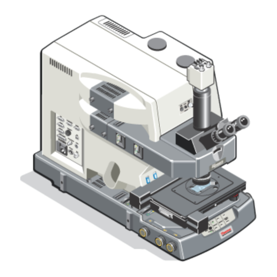
Functional description: The Continuµm is an infrared micro-sampling
system that provides the highest available IR spatial resolution and viewing
quality.
Problems associated with this assembly:
Tools required: Refer to page 4.
Estimated time required: Approximately 5-6 hours total depending on
configuration.
Notes: Refer to notes on page 6 of this document for important information.
This document contains confidential or proprietary information of Thermo Fisher Scientific. Neither this
document nor the information therein is to be reproduced, distributed, used or disclosed, either in whole or
in part, except as specifically authorized by Thermo Fisher Scientific.
7/18/2016
Continuµm
Page 1 of 32
Advertisement

Related Manuals for ThermoFisher Scientific Continuum


Summary of Contents for ThermoFisher Scientific Continuum
- Page 1 Continuµm Procedure: Service Title: Installing the Continuµm IR Microscope Installing Hardware, Software and System Configuration Revision: 01 Procedure # Install-001-2 ECCN: EAR99 Part number: 912A0572 Part description: Continuµm IR Microscope Functional description: The Continuµm is an infrared micro-sampling system that provides the highest available IR spatial resolution and viewing quality.
- Page 2 Installing the Continuµm IR Microscope - Installing Hardware, Software and System Configuration Notes Release. Revised to depict installation using the new camera. This document contains confidential or proprietary information of Thermo Fisher Scientific. Neither this document nor the information therein is to be reproduced, distributed, used or disclosed, either in whole or in part, except as specifically authorized by Thermo Fisher Scientific.
- Page 3 Installing the Continuµm IR Microscope - Installing Hardware, Software and System Configuration mportant: Prior to performing any replacement procedure, you must read the Microscope Safety Guide. If you do not have the Safety Guide, it is available for download from the PSE website. If you do not have access to the PSE website, email international support to request access at Support.Madison@thermofisher.com Safety Risks when performing this procedure:...
- Page 4 Installing the Continuµm IR Microscope - Installing Hardware, Software and System Configuration Tools required for microscope installation ½” Crescent or socket wrench Microscope gage block (iS10) Medium short Phillips screwdriver Medium Phillips screwdriver Small Phillips screwdriver ...
- Page 5 Installing the Continuµm IR Microscope - Installing Hardware, Software and System Configuration Notes: 1. This procedure describes the installation of the current configuration of the Continuµm Microscope. 2. This procedure assumes that the Continuµm microscope is being installed with a new, current model spectrometer.
- Page 6 Installing the Continuµm IR Microscope - Installing Hardware, Software and System Configuration This page intentionally left blank. This document contains confidential or proprietary information of Thermo Fisher Scientific. Neither this document nor the information therein is to be reproduced, distributed, used or disclosed, either in whole or in part, except as specifically authorized by Thermo Fisher Scientific.
- Page 7 Installing the Continuµm IR Microscope - Installing Hardware, Software and System Configuration Note If Atlµs is not installed substitute µView where applicable in this procedure. 1. Install the Continuum components. 1.1. Unpack the 15X and/or 32X condenser(s). 1.2. Prepare to install the 15X or the 32X condenser into the condenser rack.
- Page 8 Installing the Continuµm IR Microscope - Installing Hardware, Software and System Configuration 1.3. Prepare to install the 15X or the 32X condenser. If both condensers were ordered, use the 15X and set the 32X aside; the 32X will be installed and tested later in this procedure.
- Page 9 Installing the Continuµm IR Microscope - Installing Hardware, Software and System Configuration Using your fingers on one hand, gently push against the condenser to hold it in place and using your other hand; snug the lock-down screw to lock the condenser in place.
- Page 10 Installing the Continuµm IR Microscope - Installing Hardware, Software and System Configuration 2.2. Remove the stage cable, sample holder and stage tool set. Remove the X-Y stage cable, universal sample holder, and stage tool set from the shipping container and remove the packaging; set all three aside. 2.3.
- Page 11 Installing the Continuµm IR Microscope - Installing Hardware, Software and System Configuration 2.5. Square the X-Y stage and secure to the z stage dove mount. Using one hand, hold the X-Y stage flat and square to the front of the microscope and then using the 1.5mm balldriver from the stage tool set, slowly turn the balldriver clockwise while slightly rotating the stage left to right to engage the setscrew with the notch in the z stage dovemount.
- Page 12 Installing the Continuµm IR Microscope - Installing Hardware, Software and System Configuration 2.6. Unpack and set the stage controller on the tabletop. Remove the controller power supply, power cable, USB cable, driver DVD, and controller from the shipping container. Set the controller on the tabletop near enough to the microscope to attach the cables and joystick.
- Page 13 Installing the Continuµm IR Microscope - Installing Hardware, Software and System Configuration 2.10. Confirm the on/off switch located on the front of the controller is off. The switch will be in the “0” position. 2.11. Connect the power cable to the rear of the controller and the power cord to the power supply.
- Page 14 Installing the Continuµm IR Microscope - Installing Hardware, Software and System Configuration c) Use a small flat-blade screwdriver to adjust the plunger screws as necessary. Plunger screws d) Reinstall the rectangular insert and sample holder on to the motorized stage. Assure the washers are aligned with the holes, then reinstall and tighten the lock-down screws.
- Page 15 Installing the Continuµm IR Microscope - Installing Hardware, Software and System Configuration 3.2. Install the manual stage on to the z stage dove mount. Tilt and then slide the back of the stage on to the dove mount so the “tabs” on the bottom of the stage hook under the dove mount Important If the tabs do not “grab”...
- Page 16 Installing the Continuµm IR Microscope - Installing Hardware, Software and System Configuration 3.4. Install the universal sample holder. Insert the sample holder into the manual stage. Rotate the holder until the grove engages firmly with the plunger screw. Note If the sample holder is too loose or too tight in the mount, use a small flat-blade screwdriver to adjust the plunger screw on the right-side of the manual stage as necessary.
- Page 17 Installing the Continuµm IR Microscope - Installing Hardware, Software and System Configuration 4.1. Turn the power “on” to the microscope. 4.2. Using the z stage control knob on the lower right-side of the microscope, turn the knob “Down” to completely lower the z stage. 5.
- Page 18 Installing the Continuµm IR Microscope - Installing Hardware, Software and System Configuration 6.1. Back out the nosepiece set-screw. Using a 3/32” balldriver, turn the handle 1 to 1-1/2 turns counter-clockwise to slightly back-out the setscrew and allow for installation of the nosepiece. Do not remove the set-screw from the optical pod.
- Page 19 Installing the Continuµm IR Microscope - Installing Hardware, Software and System Configuration 6.2.2. Apply a gentle pressure against the front of the nosepiece assembly to hold the nosepiece against the locator pin and then turn the 3/32” balldriver clock-wise to secure the nosepiece in the mount. Do not over- tighten the set-screw.
- Page 20 Installing the Continuµm IR Microscope - Installing Hardware, Software and System Configuration 7.1. Remove the dust cap from the trinocular mount on the top of the upper optical pod. Using a 3/32” balldriver, turn the handle counter-clockwise and remove the dust cap. Continue turning the balldriver until the trinocular viewer setscrew is flush in the mount.
- Page 21 Installing the Continuµm IR Microscope - Installing Hardware, Software and System Configuration Pull the view selector to the middle position to allow viewing 7.4. from both the eyepieces and camera. 7.5. Unwrap and open the Microscope Tool Kit. 7.6. Locate the two eyepieces and remove them from their packaging. Refer to illustration above.
- Page 22 Installing the Continuµm IR Microscope - Installing Hardware, Software and System Configuration 8. Unpack the USB camera kit. 8.1. Unpack the C-mount adapter from the camera kit and remove the dust covers from each end. Pull to remove dust cap Unscrew to remove dust cap 8.2.
- Page 23 Installing the Continuµm IR Microscope - Installing Hardware, Software and System Configuration 8.3. Remove the adapter ring from the packaging. 8.4. Attach the adapter ring to the C-mount. Thread the adapter ring onto the C-mount and rotate clockwise until it stops. The adapter acts as a spacer between the c-mount and USB camera.
- Page 24 Installing the Continuµm IR Microscope - Installing Hardware, Software and System Configuration 8.6. Install the C-mount with USB camera onto the microscope. Using a 3mm balldriver, loosen the set screw on the dove mount located on top of the trinocular viewer and attach the C-mount and USB camera assembly by inserting the flanged end into the dovetail mount.
- Page 25 Installing the Continuµm IR Microscope - Installing Hardware, Software and System Configuration 8.8. Remove the 1-foot mini USB camera cable from the packaging and connect between the camera and the patch panel on the microscope. Remove the 10-foot USB camera cable from the packaging and 8.9.
- Page 26 Installing the Continuµm IR Microscope - Installing Hardware, Software and System Configuration 9. Connect the microscope Communications cable between the I/O port and COM 1 on the computer. Note If automation was not ordered you will not receive a communication cable, skip to step 10.
- Page 27 Installing the Continuµm IR Microscope - Installing Hardware, Software and System Configuration 14. Install the system software. If the OMNIC software DVD was already installed, skip to step 14.2 otherwise continue with step 14.1. 14.1. Insert the OMNIC Program Disc DVD into the DVD drive, click Install and follow the instructions on the screen.
- Page 28 Installing the Continuµm IR Microscope - Installing Hardware, Software and System Configuration 14.3. Connect the spectrometer USB cable to the computer. The Found New Hardware Wizard will appear. Click Next to launch the driver installation. Click Finish to complete the installation. ...
- Page 29 Installing the Continuµm IR Microscope - Installing Hardware, Software and System Configuration 16. Configure the microscope. Note The Continuµm can be configured two different ways; follow the appropriate as determined below to properly configure the microscope. Note Manual and Automation are optical configurations that will be a line item on the packing list.
- Page 30 Installing the Continuµm IR Microscope - Installing Hardware, Software and System Configuration C. Set the X-Y stage model to XL Motorized Stage. Leave the communication port as the default, typically COM3. D. Check the Other Options as applicable. Auto Apertures - Check for all automated systems. ...
- Page 31 Installing the Continuµm IR Microscope - Installing Hardware, Software and System Configuration c. Click Save to save the configuration settings; a digital autofocus calibration information window will appear. Click OK to close the window: digital autofocus calibration will be completed in procedure Install-001-3. If a Communication Failure dialog box appears, click OK and continue with step G otherwise, continue with step H.
- Page 32 Installing the Continuµm IR Microscope - Installing Hardware, Software and System Configuration 17. Reinstall the upper optical pod access plate. 18. Reinstall the nosepiece. 19. Continue with Install-001-3 Installing the Continuum IR Microscope - Microscope Alignment and Calibration. This document contains confidential or proprietary information of Thermo Fisher Scientific. Neither this document nor the information therein is to be reproduced, distributed, used or disclosed, either in whole or in part, except as specifically authorized by Thermo Fisher Scientific.
Need help?
Do you have a question about the Continuum and is the answer not in the manual?
Questions and answers