Advertisement
Quick Links
Procedure: Service
Title: Installing the Continuµm IR Microscope
Unpacking and Interfacing to an iS10/iS50
Revision: 01
Procedure # Install-001-1
ECCN: EAR99
Part number: 912A0572
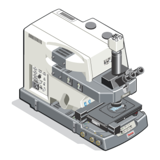
Part description: Continuµm IR Microscope
Functional description: The Continuµm is an infrared micro-sampling
system that provides the highest available IR spatial resolution and viewing
quality.
Problems associated with this assembly:
Tools required: Refer to pages 4 and 5.
Estimated time required: Approximately 5-8 hours total depending on
configuration.
Notes: Refer to notes beginning on page 6 of this document for important
information.
This document contains confidential or proprietary information of Thermo Fisher Scientific. Neither this
document nor the information therein is to be reproduced, distributed, used or disclosed, either in whole or
in part, except as specifically authorized by Thermo Fisher Scientific.
4/13/2015
Continuµm
Page 1 of 30
Advertisement

Related Manuals for ThermoFisher Scientific Continuum


Summary of Contents for ThermoFisher Scientific Continuum
- Page 1 Continuµm Procedure: Service Title: Installing the Continuµm IR Microscope Unpacking and Interfacing to an iS10/iS50 Revision: 01 Procedure # Install-001-1 ECCN: EAR99 Part number: 912A0572 Part description: Continuµm IR Microscope Functional description: The Continuµm is an infrared micro-sampling system that provides the highest available IR spatial resolution and viewing quality.
- Page 2 Installing the Continuµm IR Microscope - Unpacking and Interfacing to an iS10/iS50 Notes Release. Modified step 9.13 to include installing the purge collar and retainer ring to the purge extension. This document contains confidential or proprietary information of Thermo Fisher Scientific. Neither this document nor the information therein is to be reproduced, distributed, used or disclosed, either in whole or in part, except as specifically authorized by Thermo Fisher Scientific.
- Page 3 Installing the Continuµm IR Microscope - Unpacking and Interfacing to an iS10/iS50 mportant: Prior to performing any replacement procedure, you must read the Microscope Safety Guide. If you do not have the Safety Guide, it is available for download from the PSE website. If you do not have access to the PSE website, email international support to request access at Support.Madison@thermofisher.com Safety Risks when performing this procedure:...
- Page 4 Installing the Continuµm IR Microscope - Unpacking and Interfacing to an iS10/iS50 Tools required for applicable interface: iS10: Long handle 5/32” balldriver Long handle 3/16” balldriver 3/16” L-wrench 4 in 1 tool iS10 Service tool kit ...
- Page 5 Installing the Continuµm IR Microscope - Unpacking and Interfacing to an iS10/iS50 Tools required for microscope installation ½” Crescent or socket wrench Microscope gage block (iS10) Medium short Phillips screwdriver Medium Phillips screwdriver Small Phillips screwdriver ...
- Page 6 Installing the Continuµm IR Microscope - Unpacking and Interfacing to an iS10/iS50 Notes: 1. This procedure describes the installation of the current configuration of the Continuµm Microscope. 2. This procedure assumes that the Continuµm microscope is being installed with a new, current model spectrometer.
- Page 7 Installing the Continuµm IR Microscope - Unpacking and Interfacing to an iS10/iS50 Route the Prior fast mapping stage cable through the cable restraints when the microscope is mounted on the right- side of the iS50. The restraints are not used for a microscope mounted on the left-side.
- Page 8 Installing the Continuµm IR Microscope - Unpacking and Interfacing to an iS10/iS50 11. Detector preamp board configurations for the Continuum and iS50/iS10. Jumper settings for left-side mounted Continuµm microscope: For Detector 1 (front detector): No jumpers at N/C, A0, A1, or A2 For Detector 2 (back detector): Jumper at A0 Jumper settings for right-side mounted Continuµm microscope:...
- Page 9 Installing the Continuµm IR Microscope - Unpacking and Interfacing to an iS10/iS50 This page intentionally left blank. This document contains confidential or proprietary information of Thermo Fisher Scientific. Neither this document nor the information therein is to be reproduced, distributed, used or disclosed, either in whole or in part, except as specifically authorized by Thermo Fisher Scientific.
- Page 10 Installing the Continuµm IR Microscope - Unpacking and Interfacing to an iS10/iS50 Unpacking and interfacing to iS10/iS50/X700 1. Unpack the Continuµm microscope. Cut straps and open the box from the top by lifting the cover up and off. 2. Verify all components are present per the packing list. Check all parts against the packing list.
- Page 11 Installing the Continuµm IR Microscope - Unpacking and Interfacing to an iS10/iS50 4. Allow the microscope to reach room temperature and then remove the sleeve and plastic bag to gain easy access to the microscope. Using a ½” crescent or socket wrench, remove the bolts that secure the microscope to the wooden pallet.
- Page 12 Installing the Continuµm IR Microscope - Unpacking and Interfacing to an iS10/iS50 7. Lift the microscope off the pallet and gently set it on the work surface. Lower the back end of the microscope onto the work surface first while the front feet of the microscope are just resting near the front edge.
- Page 13 Installing the Continuµm IR Microscope - Unpacking and Interfacing to an iS10/iS50 8.2. Remove the reflection illuminator. Using a medium Phillips screwdriver, loosen the two Phillips head captive screws and then firmly pull-out on the illuminator assembly to detach the illuminator from the microscope. Set the reflection illuminator aside.
- Page 14 Installing the Continuµm IR Microscope - Unpacking and Interfacing to an iS10/iS50 8.4. Verify the DIP switch settings on the Continuµm interface board are set properly. The DIP switches of the Continuµm microscope need to be changed to allow proper motor control of the microscope. 1, 2, 5, 7 = on;...
- Page 15 Installing the Continuµm IR Microscope - Unpacking and Interfacing to an iS10/iS50 8.6. Remove the detector fill cap(s) from the top of the right-side cover. Remove the tape from the “removable” fill cap(s) and then remove the cap(s). Dispose of the tape and set the fill cap(s) aside. Note If the customer only ordered only one detector the second detector port will have a fixed cap installed.
- Page 16 Installing the Continuµm IR Microscope - Unpacking and Interfacing to an iS10/iS50 8.8. Prepare to remove the lower cover. Connect the power cord to the I/O panel of the microscope and turn the microscope ON. After the system is done initializing, use the z stage control knob on the lower right-side of the microscope to move the z stage to its upper limit if necessary.
- Page 17 Installing the Continuµm IR Microscope - Unpacking and Interfacing to an iS10/iS50 Remove the condenser purge ring from the lower cover by sliding it up and out from the microscope. Set the purge ring aside. 8.9. Remove the lower cover. Using a medium Phillips screwdriver, remove the 5 screws from the base of the lower cover and set the screws aside.
- Page 18 Installing the Continuµm IR Microscope - Unpacking and Interfacing to an iS10/iS50 8.11. Remove the shipping tape and desiccant from the iS10 as depicted below. Dispose of the tape and desiccant. 8.12. Remove the right-side window cap. Take caution not to touch the KBR window.
- Page 19 Installing the Continuµm IR Microscope - Unpacking and Interfacing to an iS10/iS50 8.14. Remove the cover from the iS10. Using a medium Phillips screwdriver, loosen the four captive screws from the cover of the iS10 as shown below and then lift the cover straight up to remove it from the spectrometer. 8.15.
- Page 20 Installing the Continuµm IR Microscope - Unpacking and Interfacing to an iS10/iS50 8.17. Attach the interface bracket to the iS10. Align the channel in the interface bracket with the locator pin under the right-side of the iS10 casting. Slide the interface bracket under the iS10 base-plate until it stops.
- Page 21 Installing the Continuµm IR Microscope - Unpacking and Interfacing to an iS10/iS50 8.19. Verify or adjust the right-back foot of the iS10. Slide the gage block into the back right screw hole of the interface bracket. If the instrument is not at the correct height, lift the iS10 at the back corner and adjust the foot by either turning the screw clockwise to raise the height or counter-clockwise to lower the height of the instrument until the base of the gage block is flush with the...
- Page 22 Installing the Continuµm IR Microscope - Unpacking and Interfacing to an iS10/iS50 Gap between the top of the thumb-screw and the bottom of the base plate. Turn and raise the thumb-screw until it touches the bottom of the base plate. Tighten the nut to lock-in the height.
- Page 23 Installing the Continuµm IR Microscope - Unpacking and Interfacing to an iS10/iS50 8.23. Verify the back, left-side height of the iS10. Tilt and slide the arm under the back-left corner of the iS10. The bottom of the casting should touch the top of the adjustment screw.
- Page 24 Installing the Continuµm IR Microscope - Unpacking and Interfacing to an iS10/iS50 8.31. Reinstall the microscope right-side cover and detector fill cap(s) removed in steps 8.7 and 8.6, respectively. 8.32. Reinstall the microscope left-side cover and reflection illuminator removed in steps 8.3 and 8.2, respectively. 8.33.
- Page 25 Installing the Continuµm IR Microscope - Unpacking and Interfacing to an iS10/iS50 8.36. Connect the auxiliary cable. Connect the Auxiliary adapter cable between the Accessory port on the I/O panel of the Continuµm and the Accessory input on the rear panel of the iS10. 8.37.
- Page 26 Installing the Continuµm IR Microscope - Unpacking and Interfacing to an iS10/iS50 9. Attach the microscope to the iS50. 9.1. Move the Continuµm microscope approximately .61 meters (2 feet) from the side of the iS50 it is to be installed on. This is to accommodate installation of the interface bracket as shown below (right-side connection depicted).
- Page 27 Installing the Continuµm IR Microscope - Unpacking and Interfacing to an iS10/iS50 9.5. Remove the purge plug screws from the iS50. Using a 5/32” balldriver, completely loosen the 2 purge plug screws from the appropriate mounting holes on the iS50 to expose the holes; refer to the diagram below. Use needle-nose pliers to remove the screws if necessary.
- Page 28 Installing the Continuµm IR Microscope - Unpacking and Interfacing to an iS10/iS50 9.7. Install the long screw through the iS50 baseplate. Insert the long screw through the mounting hole behind the sample compartment (location for right- side connection depicted). Use a 5/32” balldriver to start the screw but do not completely tighten the screw until instructed in the next step.
- Page 29 Installing the Continuµm IR Microscope - Unpacking and Interfacing to an iS10/iS50 9.8. Attach the Continuµm interface to the iS50. Insert the short screw through the appropriate mounting hole in the iS50 sample compartment (right-side connection depicted). Use a 5/32” balldriver to tighten the screw and then tighten the long screw installed in step 9.7.
- Page 30 Continuum cover extender to maintain pressure on the tube and thus hold the collar in place. Note The white retainer ring is not compatible with right-side interfaces due a limitation of the extension tube length when mounted on the left Continuum cover. Purge extension tube...
Need help?
Do you have a question about the Continuum and is the answer not in the manual?
Questions and answers