Table of Contents
Advertisement
Quick Links
Instruction Manual
D104496X012
Fisher
657C Diaphragm Actuator
™
Sizes 40i, 46i, and 60i
Contents
. . . . . . . . . . . . . . . . . . . . . . . . . . . . . . . . .
. . . . . . . . . . . . . . . . . . . . . . . . . . . . .
. . . . . . . . . . . . . . . . . . . . . . . . . . . . . . . . .
. . . . . . . . . . . . . . . . . . . . . . . . . . . . . . .
. . . . . . . . . . . . . . . . . . . . . . . . . . . . . . . . . .
. . . . . . . . . . . . . . . . . . . . . . . . . . .
. . . . . . . . . . . . . . . . . . . . . . . . . .
. . . . . . . . . . . . . . . . . . . . . . . . .
. . . . . . . . . . . . . . . . . . . . . . . . . . . . . . . .
. . . . . . . . . . . . . . . . . . . . . . . . . . . . . . .
. . . . . . . . . . . . . . . . . . . . . . . . . . . . . . . . . . .
. . . . . . . . . . . . . . . . . . . . . . . . . . . . . . . . . . .
Introduction
Scope of Manual
This instruction manual provides information on installation, adjustment, maintenance, and parts ordering for the
Fisher 657C actuator in sizes 40i, 46i, and 60i. Refer to separate instruction manuals for information about the
desuperheater positioner and other accessories used with these actuators.
Do not install, operate, or maintain a 657C actuator without being fully trained and qualified in Yarway
desuperheater, actuator, and accessory installation, operation, and maintenance. To avoid personal injury or property
damage, it is important to carefully read, understand, and follow all the contents of this manual, including all safety
cautions and warnings. If you have any questions about these instructions, contact your
proceeding.
www.Fisher.com
. . . . . . . . . . . . . . . . . . . . . . . . .
. . . . . . . . . . . . . . . . . . . . . . .
. . . . . . . . .
. . . . . . . . . . . . . . . . . . . . .
. . . . . . . . . . . . . . . . . . . . . . .
. . . . . . . . . . .
. . . . . . .
. . . . . . . . . . . . .
. . . . . . . . . .
. . . . . . . . .
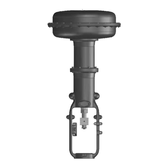
Figure 1. Fisher 657C Actuator
1
1
2
2
3
3
. . . .
4
7
7
9
10
11
11
12
12
14
16
18
18
18
18
19
19
657C Actuator (40i, 46i, and 60i)
November 2019
™
Emerson sales office
before
Advertisement
Table of Contents

Related Manuals for Emerson Fisher 657C


Summary of Contents for Emerson Fisher 657C
-
Page 1: Table Of Contents
This instruction manual provides information on installation, adjustment, maintenance, and parts ordering for the Fisher 657C actuator in sizes 40i, 46i, and 60i. Refer to separate instruction manuals for information about the desuperheater positioner and other accessories used with these actuators. -
Page 2: Description
3. Actuator travel may be less than the value listed after connecting the actuator to the valve. Description The Fisher 657C actuators (figure 1) are long stroke, spring opposed, direct‐acting diaphragm actuators. They are ™ designed for Yarway desuperheater line of products (AT-38/48, AT-37/47, AT-18/28, and 4300 Templow ). -
Page 3: Educational Services
SPRING LIFTS STEM UP STEM AF3833‐A A0792‐2 Educational Services For information on available courses for Fisher 657C diaphragm actuators, as well as a variety of other products, contact: Emerson Automation Solutions Educational Services - Registration Phone: 1-641-754-3771 or 1-800-338-8158 E-mail: education@emerson.com emerson.com/fishervalvetraining... -
Page 4: Mounting The Actuator On The Desuperheater
Instruction Manual 657C Actuator (40i, 46i, and 60i) November 2019 D104496X012 D Desuperheater/Actuator Assembly: If the actuator and desuperheater are shipped together as an assembly, it has been adjusted at the factory, and may be installed in the pipeline. After installing the desuperheater in the pipeline, refer to the Loading Connection procedures. - Page 5 Instruction Manual 657C Actuator (40i, 46i, and 60i) D104496X012 November 2019 Figure 3. Actuator Components for Size 40i, 46i, and 60i Actuators DIAPHRAGM CASINGS DIAPHRAGM DIAPHRAGM PLATE TRAVEL STOP YOKE EXTENSION ACTUATOR SPRING ACTUATOR STEM SPRING SEAT SPRING ADJUSTOR STEM CONNECTOR INTEGRAL INSTRUMENT PAD TRAVEL INDICATOR INDICATOR SCALE...
- Page 6 Instruction Manual 657C Actuator (40i, 46i, and 60i) November 2019 D104496X012 Figure 4. Construction of Yarway Desuperheater DESUPERHEATER STEM MATCH LINE FOR ACTUATOR YOKE LOCK NUT YOKE BOSS DIAMETER YARWAY DESUPERHEATER...
-
Page 7: Discussion Of Bench Set
Instruction Manual 657C Actuator (40i, 46i, and 60i) D104496X012 November 2019 Discussion of Bench Set The bench set pressure values are used to adjust the initial compression of the actuator spring with the desuperheater‐actuator assembly “on the bench.” The correct initial compression is important for the proper functioning of the desuperheater‐actuator assembly when it is put into service and the proper actuator diaphragm operating pressure is applied. - Page 8 7. If the measured travel matches the nameplate travel, bench set is complete. Proceed to the Installing the Stem Connector Assembly subsection. 8. If the measured travel is not exact, consider the spring free-length and spring rate tolerances may produce a slightly different bench set than specified. Contact your Emerson sales office for assistance.
-
Page 9: Installing The Stem Connector Assembly
Instruction Manual 657C Actuator (40i, 46i, and 60i) D104496X012 November 2019 Installing the Stem Connector Assembly When installing the stem connector assembly (key 26), the actuator and desuperheater stem threads should engage the threads of the stem connector by the distance equal to the diameter of the stem. WARNING Install the stem connector securely before a positioner is mounted to the actuator and pressurized, using only a regulator-controlled air supply, not the positioner, to move the actuator stem. -
Page 10: Friction Discussion
Instruction Manual 657C Actuator (40i, 46i, and 60i) November 2019 D104496X012 5. Screw the desuperheater stem locknuts up until the indicator disk contacts the bottom of the stem connector. Do not overtighten the locknuts. 6. Slowly stroke the desuperheater from fully closed to fully open and verify full rated travel is achieved. Be sure the desuperheater is in the closed position. -
Page 11: Deadband Measurement
Instruction Manual 657C Actuator (40i, 46i, and 60i) D104496X012 November 2019 Deadband Measurement Deadband is caused by packing friction, unbalanced forces, and other factors in the desuperheater assembly. Deadband is the range a measured signal can vary without initiating a response from the actuator (see figure 6). Each actuator spring has a fixed spring rate (force divided by compression). -
Page 12: Maintenance
Instruction Manual 657C Actuator (40i, 46i, and 60i) November 2019 D104496X012 1. Connect the loading pressure piping to the NPT internal connection in the top of the diaphragm casing. 2. If necessary, remove the 1/4 NPT bushing if a 1/2 NPT internal connection is needed to increase connection size. The connection can be made with either piping or tubing. - Page 13 Instruction Manual 657C Actuator (40i, 46i, and 60i) D104496X012 November 2019 WARNING To avoid personal injury from the precompressed spring force thrusting the upper diaphragm casing (key 1) away from the actuator, relieve spring compression (step 2), and carefully remove casing cap screws (key 22, step 4). 2.
-
Page 14: Top-Mounted Handwheel Assembly
Instruction Manual 657C Actuator (40i, 46i, and 60i) November 2019 D104496X012 3), 54 NSm (40 lbfSft) torque for size 40i actuator, or 149 NSm (110 lbfSft) torque for size 46i and 60i actuators. Slide the actuator stem and diaphragm plate (keys 10 and 4) into the yoke (key 9) and yoke extension (key 27) so the actuator spring (key 6) fits squarely between the diaphragm plate and the spring seat (key 11). - Page 15 Instruction Manual 657C Actuator (40i, 46i, and 60i) D104496X012 November 2019 Disassembly for Top‐Mounted Handwheel 1. Turn the handwheel (key 51) counter‐clockwise so that the handwheel assembly is not causing any spring compression. 2. Bypass the desuperheater, reduce loading pressure to atmospheric, and remove the tubing or piping from the upper handjack body (key 142).
-
Page 16: Casing-Mounted Adjustable Travel Stops
Instruction Manual 657C Actuator (40i, 46i, and 60i) November 2019 D104496X012 CAUTION Over‐tightening the diaphragm casing cap screws and nuts (keys 22 and 23, figure 7) can damage the diaphragm. Do not exceed 27 NSm (20 lbfSft) torque. Note Do not use lubricant on these bolts and nuts. Fasteners must be clean and dry. 8. - Page 17 Instruction Manual 657C Actuator (40i, 46i, and 60i) D104496X012 November 2019 3. Remove the upper diaphragm casing (key 1, figure 7) as outlined in the Maintenance section. 4. Remove the cap screws (keys 141) and separate the travel stop assembly from the upper casing. 5.
-
Page 18: Parts Ordering
WARNING Use only genuine Fisher replacement parts. Components that are not supplied by Emerson Automation Solutions should not, under any circumstances, be used in any Fisher actuator, because they may void your warranty, might adversely affect the performance of the actuator, and could cause personal injury and property damage. -
Page 19: Parts List
657C Actuator (40i, 46i, and 60i) D104496X012 November 2019 Parts List Top Mounted Handwheel (figure 7) Note Description Contact your Emerson sales office for part numbers. Handwheel Stop Nut Actuator Assembly Handwheel Stem Pusher Plate (figure 7) Casing‐Mounted Travel Stop Locknut 138* O‐Ring... - Page 20 Instruction Manual 657C Actuator (40i, 46i, and 60i) November 2019 D104496X012 Figure 7. Fisher 657C Actuator Sizes 40i through 60i APPLY LUB PARTS NOT SHOWN: KEY 7, 24, AND 249 NOTE: KEY 25 IS NOT PART OF SIZE 40i CONSTRUCTIONS.
- Page 21 Instruction Manual 657C Actuator (40i, 46i, and 60i) D104496X012 November 2019 Figure 8. Top-Mounted Handwheel Assembly for Size 40i through 60i Actuators 32B0262_B APPLY LUB NOTE: KEY 171 AND 246 ARE NOT PART OF SIZE 40I CONSTRUCTIONS.
- Page 22 Instruction Manual 657C Actuator (40i, 46i, and 60i) D104496X012 November 2019 Figure 9. Casing-Mounted Adjustable Down Travel Stop for Size 40i and 60i Actuators APPLY LUB Casing-Mounted Adjustable Down Travel Stop (figure 8) Description Stop Nut Travel Stop Stem Washer 139* O-RIng Cap Screw Body...
- Page 23 Instruction Manual 657C Actuator (40i, 46i, and 60i) D104496X012 November 2019...
- Page 24 Responsibility for proper selection, use, and maintenance of any product remains solely with the purchaser and end user. Fisher, Templow, and Yarway are marks owned by one of the companies in the Emerson Automation Solutions business unit of Emerson Electric Co.
Need help?
Do you have a question about the Fisher 657C and is the answer not in the manual?
Questions and answers