Table of Contents
Advertisement
Quick Links
Advertisement
Table of Contents

Subscribe to Our Youtube Channel
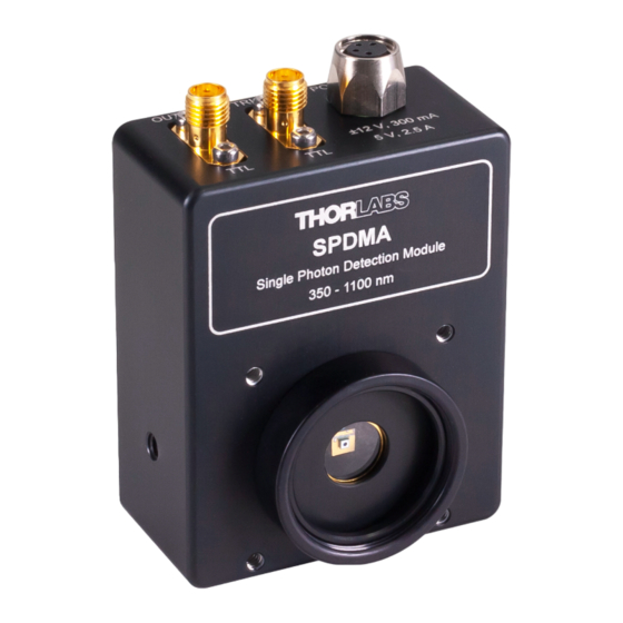
Summary of Contents for THORLABS SPDMA
- Page 1 Single Photon Detector SPDMA Operation Manual 2021...
- Page 2 Version: Date: 08-Dec-2021 Copyright © 2021 Thorlabs...
-
Page 3: Table Of Contents
5.3 Performance Plots 5.3.1 Typical Photon Detection Efficiency 5.3.2 Pulse Out Signal 5.4 Dimensions 5.5 Safety 5.6 Certifications and Compliances 5.7 Return of Devices 5.8 Manufacturer Address 5.9 Warranty 5.10 Copyright and Exclusion of Liability 5.11 Thorlabs Worldwide Contacts - WEEE Policy... - Page 4 Paragraphs preceded by this symbol explain hazards that could damage the instrument and the connected equipment or may cause loss of data. Note This manual also contains "NOTES" and "HINTS" written in this form. Please read this advice carefully! © 2021 Thorlabs...
-
Page 5: General Information
SPDMA enables high count rates. The output signal can further be optimized by continuous adjustment using the Gain Adjustment Screw. Using a TTL Trigger IN signal, the SPDMA can be externally triggered to select the time frame for the detection of single photons. -
Page 6: Getting Started
If the shipping container appears to be damaged, keep it until you have inspected the contents for completeness and tested the SPDMA mechanically and electrically. Verify that you have received the following items within the package: 1. -
Page 7: Operating Instructions
Mounting SPDMA on an Optical Table Mount the SPDMA on an optical post by using either of the three tapped mounting holes on the left and right side, and bottom of the device. The combi-thread tapped holes accept both 8-32 and M4 threads, such that using either imperial or metric TR posts is possible. -
Page 8: Operating Principle
"Pulse Out" operates at a input impedance. 3.4 Operating Principle The Thorlabs SPDMA uses a silicon avalanche photo diode (Si APD), operated in reverse di- rection and biased slightly beyond the breakdown threshold voltage V (see diagram below, point A), also known as the avalanche voltage. -
Page 9: Block Diagram And Trigger In
Using the gain adjustment screw, an overvoltage beyond the breakdown voltage can be adjus- ted to the SPDMA. This increases the photon detection efficiency but also the dark count rate. Please be aware that the probability of afterpulsing slightly rises with higher gain settings and that adjusting the gain also affects the time between photon detection and signal output. - Page 10 SPDMA 3 Operating Instructions Whenever a TTL trigger input signal is used, the default TTL input needs to be "Low". Signal from photon detection is sent to Pulse Out as the Trigger Input voltage switches to "High". High and Low signal are specified in the section Technical Data.
-
Page 11: Maintenance And Service
SPDMA 4 Maintenance and Service 4 Maintenance and Service Protect the SPDMA from adverse weather conditions. The SPDMA is not water resistant. Attention To avoid damage to the instrument, do not expose it to spray, liquids or solvents! The unit does not need regular maintenance by the user. It does not contain any modules and/or components that could be repaired by the user. -
Page 12: Appendix
SPDMA 5 Appendix 5 Appendix 5.1 Technical Data All technical data are valid at 45 ± 15% rel. humidity (non condensing). Item # SPDMA Detector Detector Type Si APD Wavelength Range 350 nm - 1100 nm Diameter of Active Detector Area... -
Page 13: Definitions
At a certain input power level, the photon count begins even to decrease with further increase in optical power. Each delivered SPDMA is tested for appropriate Saturation behavior to resemble this example. Rev: 1.0, 08-Dec-2021 ©... -
Page 14: Performance Plots
SPDMA 5 Appendix 5.3 Performance Plots 5.3.1 Typical Photon Detection Efficiency 5.3.2 Pulse Out Signal Page 10 MTN025859_D02... -
Page 15: Dimensions
SPDMA 5 Appendix 5.4 Dimensions Rev: 1.0, 08-Dec-2021 © 2021 Thorlabs Page 11... -
Page 16: Safety
Thorlabs. Attention Prior to applying power to the SPDMA, make sure that the protective conductor of the 3 con- ductor mains power cord is correctly connected to the protective earth ground contact of the socket outlet! Improper grounding can cause electric shock resulting in damage to your health or even death! All modules must only be operated with duly shielded connection cables. - Page 17 SPDMA 5 Appendix Thorlabs GmbH is not responsible for any radio television interference caused by modifications of this equipment or the substitution or attachment of connecting cables and equipment other than those specified by Thorlabs. The correction of interference caused by such unauthorized modification, substitution or attachment will be the responsibility of the user.
-
Page 18: Certifications And Compliances
SPDMA 5 Appendix 5.6 Certifications and Compliances Page 14 MTN025859_D02... -
Page 19: Return Of Devices
5.9 Warranty Thorlabs warrants material and production of the SPDMA for a period of 24 months starting with the date of shipment in accordance with and subject to the terms and conditions set forth in Thorlabs’ General Terms and Conditions of Sale which can be found at: General Terms and Conditions: https://www.thorlabs.com/Images/PDF/LG-PO-001_Thorlabs_terms_and_%20agreements.pdf... -
Page 20: Thorlabs Worldwide Contacts - Weee Policy
EC, and are not dissembled or contaminated. Contact Thorlabs for more informa- tion. Waste treatment is your own responsibility. “End of life” units must be returned to Thorlabs or handed to a company specializing in waste recovery. Do not dispose of the unit in a litter bin or at a public waste disposal site. - Page 21 www.thorlabs.com...


Need help?
Do you have a question about the SPDMA and is the answer not in the manual?
Questions and answers