Table of Contents
Advertisement
Advertisement
Table of Contents

Related Manuals for Arkel ARCODE 4B26A

Summary of Contents for Arkel ARCODE 4B26A
- Page 1 ARCODE HARDWARE MANUAL...
-
Page 2: Table Of Contents
ARCODE HARDWARE MANUAL Version : 1.01 Contents Document Change History ........................4 PREFACE & GENERAL SAFETY ......................5 EMC Conformity ........................5 Safety Information ........................5 Copyright ..........................6 OVERVIEW ............................6 General Description ........................ 6 Key Features ........................... 6 Model Number and Nameplate Check ................... - Page 3 ARCODE HARDWARE MANUAL Version : 1.01 4.3.4 Serial RS485 Ports ......................17 4.3.5 Programmable Inputs Connection ................17 4.3.6 Programmable Output Transistors ................18 4.3.7 Programmable Relay Connections ................18 4.3.8 Motor Thermostat Connection ..................18 Page 3 of 18...
-
Page 4: Document Change History
ARCODE HARDWARE MANUAL Version : 1.01 “ Document Change History Version Date Changes Author V1.00 24.07.2013 First version. Alper SÜLÜN V1.01 05.02.2013 Leds and display added. Alper SÜLÜN Page 4 of 18... -
Page 5: Preface & General Safety
ARCODE HARDWARE MANUAL Version : 1.01 1 PREFACE & GENERAL SAFETY 1.1 EMC Conformity This product is in conformity with: EN 61000-6-2 Generic standards immunity for industrial environments, EN 61000-6-4 Generic standards emission for industrial environments, EN 55011 Limits and methods of measurement of radio disturbance characteristics of industrial, scientific and medical (ISM) radio-frequency equipment and EN 61000-3-12 Limits for harmonic currents produced by equipment connected to public low-voltage systems with input current 16 A and 75 A per phase... -
Page 6: Copyright
- Special lift test menu 2.3 Model Number and Nameplate Check Arcode name plate is shown below. Model name, ınput and output ratings can be found from the nameplate as well unique serial number which identifies device in the Arkel. Page 6 of 18... -
Page 7: Optional Boards
ARCODE HARDWARE MANUAL Version : 1.01 Model name of the given nameplate can be expressed as follows 4B26A : 4 : 340-420VAC nominal supply voltage B : B size case 26A: Maximum 26Amp driver Following table summarize power drive capabilities and casing varieties. MOTOR POWER NOMINAL OUTPUT MODEL... -
Page 8: Mechanical Installation
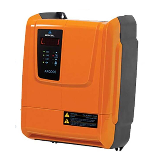
ARCODE HARDWARE MANUAL Version : 1.01 2.5 Main Unit Indicators Main unit contains 4 digit 7-segment display and 8 Led indicators. Some basic information can be obtained from 7-segment display. The information can be speed value, error number, floor number or main state of the Arcode unit. Additionally leds are used to indicate current state of the safety circuit nodes as well main movements. - Page 9 ARCODE HARDWARE MANUAL Version : 1.01 fluctuations. When using the drive in an enclosure panel, install a cooling fan or air conditioner in the area to ensure that the air temperature inside the enclosure does not exceed the specified levels. Do not allow ice to develop on the drive.
-
Page 10: Mechanical Dimensions
ARCODE HARDWARE MANUAL Version : 1.01 3.2 Mechanical Dimensions 3.2.1 B size case dimensions B size mechanics Width x length x height (mm) 257,5x372,5x194.75 Weight 9.5Kg. 3.2.2 C size case dimensions Page 10 of 18... -
Page 11: Installation Orientation And Spacing
ARCODE HARDWARE MANUAL Version : 1.01 C size mechanics Width x length x height (mm) 257.5x472x29 Weight 11.5kg 3.3 Installation Orientation and Spacing Arcode should be installed vertical orientation on a robust surface that can carry Arcode with 4 screws and 4 nuts. Recommended screw/nut dimensions is metric 6 and recommended surface is metal sheet. - Page 12 ARCODE HARDWARE MANUAL Version : 1.01 Remove optional boards cover Install the optional board with 4 screws within 4 corner. And connect the flat cable already installed in the Arcode Place the SD card to it’s location. Page 12 of 18...
-
Page 13: Electrical Installation
ARCODE HARDWARE MANUAL Version : 1.01 4 ELECTRICAL INSTALLATION 4.1 TECHNICAL SPECIFICATIONS DRIVER Model Name 4B14A 4B17A 4B26A Optimum Machine Power 5.5 kW(7.5HP) 7.5 kW(10HP) 11 kW(15HP) Nom. Output Current(Inom) 14 A 17 A 26 A Max. Output Current (< 6 s) 28 A 34 A 52 A... -
Page 14: Driver Side Connections
ARCODE HARDWARE MANUAL Version : 1.01 Transistors outputs 4 programmable transistor outputs(open collector Imax:200mA) Door bridging Door bridging board connector (reserved) Cooling Air ventilation and aluminum cooler Safety circuit 48-110-220VAC User interface 4 digit seven segment plus 8 LED indicator Logging SD card logging 4.2 DRIVER SIDE CONNECTIONS... -
Page 15: Encoder Connection
ARCODE HARDWARE MANUAL Version : 1.01 4.2.5 Encoder Connection Arcode support various types of encoder can be found on the market. For asynchronous motors incremental encoders which are cost effective are enough while absolute encoders are required for synchronous motors. Encoders are very sensitive devices for electromagnetic interferences. -
Page 16: Controller Side Connections
ARCODE HARDWARE MANUAL Version : 1.01 Incremental signal B positive Incremental signal B negative Incremental signal Z (index) positive Incremental signal Z (index) negative Analogue Incremental signal A positive Analogue Incremental signal A positive Analogue Incremental signal B Positive Analogue Incremental signal B negative Absolute position serial channel clock positive Absolute position serial channel clock negative Absolute position serial channel data positive... -
Page 17: Safety Circuit Connection
ARCODE HARDWARE MANUAL Version : 1.01 4.3.1 Safety Circuit Connection Door contacts of the safety circuit need to be connected to the Arcode for 2 reasons. First safety circuit door contacts monitoring and second is the bridging of the door contacts for re-leveling or pre-opening. - Page 18 ARCODE HARDWARE MANUAL Version : 1.01 4.3.6 Programmable Output Transistors Arcode has 4 open collector output whose functions are programmable. Each output is designed in a optically isolated topology and has 200mA current limit which provided with a PTC. Reference circuit for each input line is presented below for right usage.
Need help?
Do you have a question about the ARCODE 4B26A and is the answer not in the manual?
Questions and answers