
Subscribe to Our Youtube Channel
Related Manuals for Gree GWH18KG-K3DNA6G/I


Summary of Contents for Gree GWH18KG-K3DNA6G/I
- Page 1 Change for Life Service Manual Model: GWH18KG-K3DNA6G/I (Refrigerant R410A) GREE ELECTRIC APPLIANCES,INC.OF ZHUHAI...
-
Page 2: Table Of Contents
Service Manual Table of Contents Part Ⅰ : Technical Information ................. 1 1. Summary ........................1 2. Specifications ......................2 3. Outline Dimension Diagram ................3 4. Refrigerant System Diagram ................ 4 5. Electrical Part ......................5 5.1 Wiring Diagram ........................5 5.2 PCB Printed Diagram ...................... - Page 3 Service Manual Appendix: ..........................39 Appendix 1: Reference Sheet of Celsius and Fahrenheit ............39 Appendix 2: Configuration of Connection Pipe ................39 Appendix 3: Pipe Expanding Method ..................40 Appendix 4: List of Resistance for Temperature Sensor ............41 Table of Contents...
-
Page 4: Part Ⅰ : Technical Information
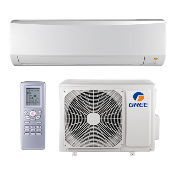
Service Manual Part Ⅰ : Technical Information 1. Summary Indoor Unit GWH18KG-K3DNA6G/I Remote Controller H O U R ONOFF YAA1FB Technical Information... -
Page 5: Specifications
Service Manual 2. Specifications 2.1 Specification Sheet Model GWH18KG-K3DNA6G/I Product Code CB146N36000 Rated Voltage 220-240 Rated Frequency Phases Power Supply Mode Outdoor Cooling Capacity(Min~Max) 5275(1200~6200) Heating Capacity(Min~Max) 5570(1100~6000) Cooling Power Input(Min~Max) 1675(380~2450) Heating Power Input(Min~Max) 1750(350~2600) Air Flow Volume (SH/H/M/L) -
Page 6: Outline Dimension Diagram
Service Manual 3. Outline Dimension Diagram 3.1 Indoor Unit 120.5 548.5 Φ55 Φ55 41.3 41.3 54.5 120.5 548.5 unit:mm Φ55 Φ55 Φ55 Φ55 Model 41.3 41.3 54.5 Φ70 Φ70 Φ55 Φ55 Φ70 Φ70 Technical Information... -
Page 7: Refrigerant System Diagram
Service Manual 4. Refrigerant System Diagram Outdoor unit Indoor unit Gas pipe side Valve 4-Way valve Di s charge Heat Suction Accumlator exchanger Compressor (evaporator) Heat exchanger Liquid pipe (condenser) side Valve Strainer Electric Capillary Strainer expand valve COOLING HEATING Connection pipe specification: Liquid pipe:1/4"... -
Page 8: Electrical Part
Service Manual 5. Electrical Part 5.1 Wiring Diagram ● Instruction Symbol Symbol Color Symbol Symbol Color Symbol Name White Green Jumper cap Yellow Brown COMP Compressor Blue Grounding wire YEGN Yellow/Green Black Violet Orange Note: Jumper cap is used to determine fan speed and the swing angle of horizontal lover for this model. ●... -
Page 9: Pcb Printed Diagram
Service Manual 5.2 PCB Printed Diagram Indoor Unit ● Top view Name Interface of health function neutral wire Interface of live wire Interface of neutral wire Capacitor of fan motor Fuse Interface of PG motor Interface of health function live wire Auto button Up &... -
Page 10: Function And Control
Service Manual 6. Function and Control 6.1 Remote Controller Introduction ON/OFF button - button + button MODE button H O U R ONOFF FAN button SWING button I FEEL button button SLEEP button TEMP button TIMER-ON button CLOCK button TIMER-OFF button TURBO button LIGHT... - Page 11 Service Manual no display Technical Information...
- Page 12 Service Manual Technical Information...
- Page 13 Service Manual battery reinstall remove Cover of battery box Technical Information...
-
Page 14: Brief Description Of Modes And Functions
Service Manual 6.2 Brief Description of Modes and Functions Indoor Part Temperature Parameter ◆ Room setting temperature (Tpreset) ◆ Room ambient temperature (Tamb.) (temperature sensor :15K, partial pressure resistance:15K) ◆ Surface temperature of copper pipe for indoor heat exchanger (Tindoor tube) (temperature sensor: 20K, partial pressure resistance: 20K) 1. - Page 15 Service Manual remote controller. ② Only when the remote control signal is switched to indoor ambient temperature display status from other display status, controller will display the indoor ambient temperature for 3s and then turn back to display the setting temperature. ③...
- Page 16 Service Manual (6) Blow Function Blow function can be set in cooling and dry mode. (7) Indoor Fan Control Indoor fan can be set at super-high, high, medium or low. Meanwhile, the fan will operate at super-high, high, medium and low fan speed respectively and it can also set at auto fan speed.
-
Page 17: Part Ⅱ : Installation And Maintenance
Service Manual Part Ⅱ : Installation and Maintenance 7. Notes for Installation and Maintenance Safety Precautions: 10. If the power cord or connection wire is not long enough, please get the specialized power cord or connection wire Important! from the manufacture or distributor. Prohibit prolong the wire by yourself. - Page 18 Service Manual Main Tools for Installation and Maintenance 1. Level meter, measuring tape 2. Screw driver 3. Impact drill, drill head, electric drill 4. Electroprobe 5. Universal meter 6. Torque wrench, open-end wrench, inner hexagon spanner 7. Electronic leakage detector 8.
-
Page 19: Installation
Service Manual 8. Installation 8.1 Installation Dimension Diagram Space to the wall At least 15cm At least 15cm Space to the wall Drainage pipe Installation and Maintenance... - Page 20 Service Manual Installation procedures Start installation Preparation before installation Read the requirements select installation Prepare tools for electric connection location Select indoor unit Select outdoor unit installation location installation location Install the support of outdoor unit Install wall-mounting (select it according to the actual situation) frame, drill wall holes Connect pipes of indoor Fix outdoor unit...
-
Page 21: Installation Parts-Checking
Service Manual 8.2 Installation Parts-checking 8.4 Electric Connection Requirement 1. Safety Precaution Name Name (1) Must follow the electric safety regulations when installing Indoor unit Sealing gum the unit. Outdoor unit Wrapping tape (2) According to the local safety regulations, use qualified Support of outdoor Connection pipe power supply circuit and air switch. - Page 22 Service Manual (3) Fix the wall-mounting frame on the wall with tapping screws Left Right (ST4.2X25TA) and then check if the frame is firmly installed by pulling the frame. If the plastic expansion particle is loose, please drill another fixing hole nearby. Cut off Fig.4 the hole...
- Page 23 Service Manual Note: Note: (1) All wires of indoor unit and outdoor unit should be (1) Add insulating pipe in the indoor drain hose in order to connected by a professional. prevent condensation. (2) If the length of power connection wire is insufficient, please (2) The plastic expansion particles are not provided.
-
Page 24: Check After Installation And Test Operation
Service Manual Outdoor Indoor Fig.17 Wall pipe Sealing gum Upper hook Fig.16 Lower hook of wall-mounting frame Note: Do not bend the drain hose too excessively in order to prevent blocking. 8.6 Check after Installation and Test Operation 1. Check after Installation Check according to the following requirement after finishing installation. -
Page 25: Maintenance
Service Manual 9. Maintenance 9.1 Malfunction Display of Indoor Unit 1. Malfunction display requirement When there are several malfunctions, they will be displayed circularly. 2. Malfunction display method (1) Hardware malfunction: immediate display; refer to “malfunction display table”; (2) Operation state: immediate display; refer to “malfunction display table”; (3) Other malfunctions: it is displayed after the compressor stops for 200s;... - Page 26 Service Manual ●Discharging method (1) remove the inverter cover(Outdoor Unit) Inverter cover P.C.board (Soldered surface) (2)As shown below,connect the discharge resistance(approx.100Ω20W)or plug of the sold ering iron to voltage between + - terminals of the electrolytic capacitor on PC Board for 30s, and then peformedischarging. NOTE: A large-capacity electrolytic capacitor is used in the outdoor unit controller(inverter).Therefore,if the power supply is turned off,charge(charging voltage DC280V to 380V)remains and disc harging takes a lot of time..
-
Page 27: Procedure Of Troubleshooting
Service Manual 9.2 Procedure of Troubleshooting (1) Malfunction of Temperature Sensor (F1, F2) Main detection points: ● Is the wiring terminal between the temperature sensor and the controller loosened or poorly contacted? ● Is there short circuit due to trip-over of the parts? ●... - Page 28 Service Manual (2) Malfunction of Blocked Protection of IDU Fan Motor (H6) Main detection points: ● SmoothlyIs the control terminal of PG motor connected tightly? ● SmoothlyIs the feedback interface of PG motor connected tightly? ● The fan motor can't operate? ●...
- Page 29 Service Manual (3) Malfunction of Protection of Jumper Cap (C5) Main detection points: ● Is there jumper cap on the mainboard? ● Is the jumper cap inserted correctly and tightly? ● The jumper is broken? ● The motor is broken? ●...
- Page 30 Service Manual (4) Malfunction of Zero-crossing Inspection Circuit Malfunction of the IDU Fan Motor (U8) Main detection points: ● Instant energization afte de-energization while the capacitordischarges slowly? ● The zero-cross detectioncircuit of the mainboard is defined abnormal? Malfunction diagnosis process: Start Turn power off for 1minute,the turn...
- Page 31 Service Manual (4) Communication malfunction (E6) Troubleshooting for E6 malfunction Disconnect power and check if the connection wire of indoor and outdoor units and the built-in wire of electric box are correctly connected. Connect the wire properly according Is malfunction Correct connection? to the wiring eliminated?
-
Page 32: Troubleshooting For Normal Malfunction
Service Manual 9.3 Troubleshooting for Normal Malfunction 1. Air Conditioner Can't be Started Up Possible Causes Discriminating Method (Air conditioner Status) Troubleshooting Confirm whether it's due to power failure. If yes, No power supply, or poor After energization, operation indicator isn’t bright wait for power recovery. - Page 33 Service Manual 4. Air Conditioner is Leaking Possible causes Discriminating method (air conditioner status) Troubleshooting Eliminate the foreign objects inside the drain Drain pipe is blocked Water leaking from indoor unit pipe Drain pipe is broken Water leaking from drain pipe Replace drain pipe Water leaking from the pipe connection place of Wrapping is not tight...
-
Page 34: Exploded View And Parts List
Service Manual 10. Exploded View and Parts List Indoor Unit AUTO HEALTH X-FAN HUMIDITY FILTER TURBO HOUR ON/OFF ON/OFF MODE X-FAN TEMP TIMER TURBO SLEEP LIGHT Installation and Maintenance... - Page 35 Service Manual Part Code Description GWH18KG-K3DNA6G/I (Cold Plasma) Product Code CB146N36000 Front Panel 20012495 Filter Sub-Assy 11122104 Screw Cover 242520041 Front Case Assy 20012497 Guide Louver 10512140 Air Louver 10512160 Helicoid tongue 26112232 Left Axile Bush 10512037 Rear Case assy...
-
Page 36: Removal Procedure
Service Manual 11. Removal Procedure Warning: Be sure to wait for a minimum of 20 minutes after turning off all power supplies and discharge the refrigerant completely before removal. Removal Procedure of Intdoor Unit Points Procedure Steps 1. External features If ON/OFF button is kept pushing ■... - Page 37 Service Manual Points Procedure Steps 3. Opening and shutting front panel Draw out the axial bush. Bend the horizontal louver slightly and then remove it. Support the front panel by one ■ hand, while remove the rotation axis at the upper center by the other hand.
- Page 38 Service Manual Points Steps Procedure 4. Opening and closing of service cover Remove a service cover mounting screw. Open service cover upward. A switch for field setting is ■ not provided in particular. screws 5. Removal of front grille assembly Remove the 5 screws, in the right and the left, ■...
- Page 39 Service Manual Points Procedure Steps 6. Remove electrical box Disconnect the cable Pay attention to the direction ■ clamp of the retainer of the thermistor so that the retainer will not touch the harness (same as the existing models.) Remove Temperature Heat exchanger thermistor Sensor;...
- Page 40 Service Manual Points Procedure Steps 7. Remove piping fixture. Remove Pipe Clamp Auxiliary piping Piping fixture Auxiliary piping Adjust the pipeline slightly Loosen the screws, Heat exchanger in the right and the left, which fix the Evaporator Assy. Remove Evaporator Assy Installation and Maintenance...
- Page 41 Service Manual Points Procedure Steps 8. Remove the pressure plate of motor Pressure plate of motor Remove screws of motor press plate and then remove the motor press plate. 9. Remove shaft cushion rubber base Shaft cushion rubber base Remove motor, blade and shaft cushion rubber base.
-
Page 42: Appendix
Service Manual Appendix: Appendix 1: Reference Sheet of Celsius and Fahrenheit Conversion formula for Fahrenheit degree and Celsius degree: Tf=Tcx1.8+32 Set temperature Fahrenheit Fahrenheit Fahrenheit display Fahrenheit display Fahrenheit display Fahrenheit Celsius( Celsius( Celsius( temperature temperature temperature 60.8 69/70 69.8 78/79 78.8 62/63... -
Page 43: Appendix 3: Pipe Expanding Method
Service Manual Appendix 3: Pipe Expanding Method Pipe Note: Pipe cutter Improper pipe expanding is the main cause of refrigerant leakage.Please expand the pipe according to the following steps: Leaning Uneven Burr A:Cut the pip ● Confirm the pipe length according to the distance of indoor unit and outdoor unit. ●... -
Page 44: Appendix 4: List Of Resistance For Temperature Sensor
Service Manual Appendix 4: List of Resistance for Temperature Sensor Resistance Table of Ambient Temperature Sensor for Indoor and Outdoor (15K) Temp( C) Resistance(kΩ) Temp( C) Resistance(kΩ) Temp( Resistance(kΩ) Temp( Resistance(kΩ) 138.1 18.75 3.848 1.071 128.6 17.93 3.711 1.039 121.6 17.14 3.579 1.009... - Page 45 Service Manual Resistance Table of Tube Temperature Sensors for Indoor and Outdoor (20K) Temp( C) Resistance(kΩ) Temp( C) Resistance(kΩ) Temp( Resistance(kΩ) Temp( Resistance(kΩ) 181.4 25.01 5.13 1.427 171.4 23.9 4.948 1.386 162.1 22.85 4.773 1.346 153.3 21.85 4.605 1.307 20.9 4.443 1.269 137.2...
- Page 46 Service Manual Resistance Table of Discharge Temperature Sensor for Outdoor (50K) Temp( C) Resistance(kΩ) Temp( Resistance(kΩ) Temp( C) Resistance(kΩ) Temp( Resistance(kΩ) 853.5 18.34 4.75 799.8 93.42 17.65 4.61 89.07 16.99 4.47 703.8 84.95 16.36 4.33 660.8 81.05 15.75 4.20 620.8 77.35 15.17 4.08...
- Page 47 GREE ELECTRIC APPLIANCES,INC.OF ZHUHAI Add: West Jinji Rd, Qianshan, Zhuhai, Guangdong, China 519070 Tel: (+86-756) 8522218 Fax: (+86-756) 8669426 Email: gree@gree.com.cn Http://www.gree.com HONG KONG GREE ELECTRIC APPLIANCES SALES LIMITED Add: Unit 2612,26/F.,Miramar Tower 132 Nathan Road,TST,Kowloon,HK Tel: (852) 31658898 Fax: (852) 31651029...
Need help?
Do you have a question about the GWH18KG-K3DNA6G/I and is the answer not in the manual?
Questions and answers