Table of Contents
Advertisement
Quick Links
Advertisement
Table of Contents

Related Manuals for Alpha Outback Energy Tri Power X33 HE

Summary of Contents for Alpha Outback Energy Tri Power X33 HE
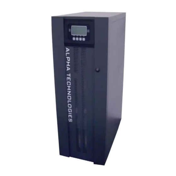
- Page 1 Tri Power X33 HE 30-125KVA User Manual Page...
- Page 2 Alpha and Outback Energy is specialised in the design, development and production of Uninterruptible Power Supplies (UPS) The TRI POWER X33 HE described in this manual is a high quality, meticulously designed product, built to guarantee the best performance. This manual contains detailed instructions on how to use and install this product.
-
Page 3: Table Of Contents
Preliminary check of contents ..........................14 Positioning the Tri Power X33 HE ........................... 14 Operations to access the terminals of the Tri Power X33 HE ................. 14 Electrical connections ..........................15 Diagrams of connections to the electrical system ....................15 Tri Power X33 HE internal protections ........................ - Page 4 Communication ports ..........................37 RS232 AND USB CONNECTORS .......................... 37 Communication Slot ..............................38 AS400 PORT ................................38 Buzzer ..............................40 Software ..............................41 Monitoring and control software ..........................41 Configuration software ............................. 41 Troubleshooting ......................... 42 Status / alarm codes ..........................46 Technical data ..........................
-
Page 5: Overview
Overview Tri Power X33 HE 30 - 40 30 – 40 The TRI POWER X33 HEs in the series have been designed using state-of-the-art technology, in order to ensure the best performance for the user. The use of the new control boards based on microprocessor architecture (DSP + µP inside), together with the adoption of specific circuit solutions that use last-generation components, have... -
Page 6: Front Views Of The Tri Power X33 He
Front views of the Tri Power X33 HE Control panel with graphic display Wheels for moving the TRI POWER X33 HE Front door with lock Brake rod Ventilation grid Page... - Page 7 From the left: Slot for auxiliary communication board Input isolator / Separate bypass isolator (optional) / Manual bypass isolator / Output isolator From the left: Battery start button (COLD START) / R.E.P.O. (Remote Emergency Power Off) Terminal cover connector / Contact holder for AS400 / communication port RS232...
-
Page 8: Views Of The Tri Power X33 He Connections
Views of the Tri Power X33 HE connections Power connections: EXTERNAL BATTERY, INPUT, SEPARATE BYPASS (optional), OUTPUT Connection for external synchronization signal Connection for remote maintenance bypass command Connection for external Battery Box temperature probe Page... -
Page 9: Rear View Of The Tri Power X33 He
Rear view of the Tri Power X33 HE Parallel board slot (optional) Power board fans Powershare socket / Power out socket Battery charger fan Power relay board slot (optional) Page... -
Page 10: View Of The Control Panel
The TRI POWER X33 HE series with Separate Bypass allows a separate connection between the input and the bypass lines. The TRI POWER X33 HE output is synchronised with the bypass line, in order to avoid incorrect voltage changeovers during the alternate phases, in case an automatic bypass or a maintenance isolator closure occurs. -
Page 11: Installation
The table shows an example of a flow rate with (t a - t e ) =5°C and a rated resistive load (pf=0.9). (Note: This formula is applicable only if ta>te. If not, the TRI POWER X33 HE installation requires an air- conditioning system). -
Page 12: Electromagnetic Compatibility
Avoid dusty environments Make sure that the floor is level and that it is able to withstand the weight of the TRI POWER X33 HE (and of the Battery Box) Avoid environments which are too narrow, as they could impede normal maintenance operations The relative humidity should not exceed 90% with no condensation Make sure that the ambient temperature remains between 0 and 40°C while the TRI POWER X33 HE is... -
Page 13: Removing The Tri Power X33 He From The Pallet
Removing the TRI POWER X33 HE from the pallet CAUTION! TO AVOID HARMING PEOPLE AND/OR DAMAGING THE EQUIPMENT, FOLLOW CAREFULLY THE FOLLOWING INSTRUCTIONS. SOME OF THESE INSTRUCTIONS NEED TO BE CARRIED OUT BY TWO PEOPLE. straps remove Remove the 2 brackets securing the TRI POWER X33 cardboard box by sliding it upwards. - Page 14 Screw the brake rod completely, so to separate it from the pallet Make sure that the door is firmly closed. CAUTION! Push the TRI POWER X33 HE from the rear with great care. Given the weight of the equipment, this operation needs to be carried out by two people.
-
Page 15: Preliminary Check Of Contents
(≥ 1,5 metres). The rear part of the TRI POWER X33 HE should be placed at least at 30 cm from the wall, to allow the air blown by the ventilation fans to outflow correctly. -
Page 16: Electrical Connections
WARNING: a 4-wire three-phase distribution system is required. The TRI POWER X33 HE must be connected to a power supply line made up of 3 phases + neutral + PE (protective earth) of TT, TN or IT type. Therefore, the phase rotation must be respected. - Page 17 TRI POWER X33 HE with no modification of the neutral regime and with separate bypass input TRI POWER X33 HE with input galvanic isolation and with separate bypass input TRI POWER X33 HE with output galvanic isolation and separate bypass input...
- Page 18 In case the two power supplies were different, an isolation transformer would be necessary on one of the inputs. TRI POWER X33 HE with no modification of the neutral regime and with separate bypass input connected to an independent power supply line...
-
Page 19: Tri Power X33 He Internal Protections
Short circuit If a fault occurs on the load, the TRI POWER X33 HE protects itself by limiting the value and the duration of the current supplied (short circuit current). These values also depend on the TRI POWER X33 HE operating status at the... -
Page 20: External Protection Devices
In the absence of an input separating transformer, the neutral from the mains power supply is connected to the neutral of the TRI POWER X33 HE output. This way the neutral regime of the equipment is not modified. THE INPUT NEUTRAL IS CONNECTED TO THE OUTPUT NEUTRAL... -
Page 21: Cross Section Of The Cables
Cross section of the cables We recommend that the INPUT/OUTPUT and the BATTERY cables pass under the TRI POWER X33 HE. As for the dimensioning of the cross section of the input and output cables, please refer to the following table:... -
Page 22: Connections Of The Model With Separate Bypass
Connections to the BATTERY module are required only when the optional Battery Box is present R.E.P.O. This isolated input is used to turn off the TRI POWER X33 HE remotely in case of emergency. This TRI POWER X33 HE is provided from the factory with “Remote Emergency Power Off” (R.E.P.O.) terminals short-circuited (see "Views of the TRI POWER X33 HE connections"). -
Page 23: External Sync
The Company provides this accessory already pre-assembled in an IP65 plastic box. It is essential to connect the "SERVICE BYPASS" terminal (see "Views of the TRI POWER X33 HE connections") to the auxiliary contact of the SERVICE BYPASS switch. The closure of the SERVICE BYPASS switch will open this auxiliary contact which informs the TRI POWER X33 HE that the maintenance bypass has been inserted. - Page 24 Peripheral switchboard TRI POWER X33 HE internal connections INPUT switch: isolator compliant with the indications given in the "TRI POWER X33 HE internal protections" section OUTPUT switch: isolator compliant with the indications given in the "TRI POWER X33 HE internal protections"...
-
Page 25: Connecting The Tri Power X33 He To The Battery Box (Optional)
SWIN input isolator of the TRI POWER X33 HE. The load should continue to be powered, and the “battery power” LED should light up on the TRI POWER X33 HE control panel. The latter should beep at regular intervals. Once the SWIN input isolator has been closed again, the TRI POWER X33 HE should resume operating on mains power. -
Page 26: Setting The Nominal Battery Capacity - Software Configuration
This configuration can be carried out either by using the advanced configuration software TRI POWER X33 HE Tools in the CD- ROM provided with the TRI POWER X33 HE, or directly from the TRI POWER X33 HE control panel. Installing and running TRI POWER X33 HETools: Follow the installation and operating instructions contained in the software manual provided in the TRI POWER X33 HE Tools folder in the CD-ROM. -
Page 27: Use
Description The purpose of this TRI POWER X33 HE is to ensure a perfect power supply voltage for the devices connected to it, whether mains power is present, or not. Once it has been connected and powered, the TRI POWER X33 HE generates a sinusoidal alternating voltage with stable amplitude and frequency, regardless of any sudden change or variation in the mains supply. -
Page 28: Preliminary Operations And First Start-Up
WARNING: if an external Battery Box is present and the connection does not comply with the instructions given in "Connecting the TRI POWER X33 HE to the Battery Box (optional)" paragraph, the battery fuses and other protections may result damaged. In that case, please contact the Customer Service department, in order to prevent further damages to the TRI POWER X33 HE. - Page 29 Wait for the display to turn off Open the battery fuse holders Open all the protections Tri Power X33 HEtream the TRI POWER X33 HE Remove the protective panel covering the input terminal board Correct the position of the input wires so that the cyclic sense of the phases is respected.
-
Page 30: Mains Start-Up
7 seconds. The start-up sequence ends when the TRI POWER X33 HE enters “battery working” mode. Note: if the sequence described above is not carried out within 1 minute, the TRI POWER X33 HE will turn off automatically so not to discharge the batteries unnecessarily. Switching off the TRI POWER X33 HE From the main menu, select the “SWITCH OFF”... -
Page 31: Graphic Display
Located at the centre of the control panel there is a large graphic display, which provides, in the foreground and in real-time, a detailed overview of the TRI POWER X33 HE status. The user can switch on and off the TRI POWER X33 HE, consult the electrical measurements of the mains, output, battery etc. -
Page 32: Menu Display
Menu display Page... -
Page 33: Operating Mode
Listed below are the operations to be performed in order to carry out the maintenance on the equipment with no interruption of the power supply to the load: With the mains voltage present, the TRI POWER X33 HE must power the load through the inverter or the automatic bypass. -
Page 34: Redundant Auxiliary Power Supply For Automatic Bypass
(within a tolerance range which can be set by the user) with the input voltage, in order to allow use of the bypass. Outside this tolerance range, the TRI POWER X33 HE desynchronises adopting the nominal frequency and the bypass can no longer be used (free running mode). -
Page 35: Power Reduction For 200/208V Phase-Neutral Loads
Power reduction for 200/208V phase-neutral loads In case the output voltage is set to 200V or 208V PHASE-NEUTRAL (see the “Configuring the TRI POWER X33 HE” paragraph), the maximum power output of the TRI POWER X33 HE is reduced compared to its nominal value, as... -
Page 36: Configuring The Tri Power X33 He
Configuring the Tri Power X33 HE The table below shows all the possible configurations available to better adapt the TRI POWER X33 HE to the user’s needs. CP (Control Panel) = Indicates that the configuration can be changed from the control panel, as well as from the configuration software. - Page 37 Not enabled temperature probe Not enabled external temperature probe Enabled (optional) * Once these output voltage values are set, the TRI POWER X33 HE output power is reduced (see the “Power reduction for 200V and 208V phase-neutral loads” paragraph) Page...
-
Page 38: Communication Ports
Communication ports In the upper part of the TRI POWER X33 HE, behind the door (see "Views of the TRI POWER X33 HE") there are the following communication ports: Serial port, available with RS232 connector and USB connector. NOTE: the choice of one connector automatically excludes the other. -
Page 39: Communication Slot
Communication Slot This TRI POWER X33 HE is equipped with two expansion slots for accessory communication boards, which allow the device to communicate using the main communication standards (see the "Front views of the TRI POWER X33 HE" paragraph). Here are some examples:... - Page 40 N.B.: The figure shows the contacts present inside the TRI POWER X33 HE, which are capable of carrying a max. current of 0.5A to 42Vdc. The position of the contact indicated in the figure is with no alarm or signal present.
-
Page 41: Buzzer
Buzzer The status and the faults of the TRI POWER X33 HE are signalled by the buzzer, which will emit a sound according to the various operating conditions of the TRI POWER X33 HE. The various kinds of sounds are described below: Sound A: This signal is emitted when the TRI POWER X33 HE is turned on or off using the apposite buttons. -
Page 42: Software
Connect the RS232 communication port of the TRI POWER X33 HE to a COM communication port of the PC via the serial cable provided* or connect the USB port of the TRI POWER X33 HE to a USB port of the PC using a standard USB cable*. -
Page 43: Troubleshooting
STAND-BY. In case it is in stand-by, turn the TRI POWER X33 HE on by accessing the “SYSTEM ON” menu, and wait for the start-up sequence to be completed before removing the maintenance BYPASS. read carefully the sequence described in the “maintenance BYPASS (SWMB)”... - Page 44 A30, A32, A33, A34 Activate the maintenance bypass (SWMB), turn the AND THE TRI POWER FAULT IN HEAT SINK TRI POWER X33 HE off and back on again and X33 HE DOES TEMPERATURE PROBE exclude the maintenance bypass. If the problem...
- Page 45 THRESHOLD THE DISPLAY SHOWS Activate the maintenance bypass (SWMB), switch ONE OR MORE OF THE INPUT RELAY LOCKED off the TRI POWER X33 HE, open the SWIN and FOLLOWING CODES: contact the nearest service centre. F06, F07, F08 FAULT IN:...
- Page 46 BATTERY CHARGER COOLING SYSTEM Activate the maintenance bypass (SWMB). Switch THE DISPLAY SHOWS off the TRI POWER X33 HE, wait for a minute and ONE OR MORE OF THE STATIC BYPASS turn the TRI POWER X33 HE back on. Exclude the...
-
Page 47: Status / Alarm Codes
Status / alarm codes By using a sophisticated self-diagnostic system, this TRI POWER X33 HE can check and indicate on the display panel its status and any error and/or fault occurred during operation. Whenever a problem arises, the TRI POWER X33 HE signals the event by showing the code and the corresponding alarm on the display. - Page 48 “minor” problems, which do not bring the TRI POWER X33 HE to a halt, but can Anomalies: reduce its performance or inhibit the use of some of its functions. CODE DESCRIPTION Inverter not synchronised External synchronism failed Overvoltage on input line of Phase1...
- Page 49 These are more critical problems compared to the “Anomalies”, as if they persist they may bring the Faults: TRI POWER X33 HE to a halt even in a very short time. CODE DESCRIPTION Internal communication error Wrong cyclic sense of the input phases...
- Page 50 Locks: these codes indicate that the TRI POWER X33 HE, or one of its parts, is locked. Usually, they are preceded by an alarm signal. In case of faults and consequent locking of the inverter, the latter will be turned off and the load will be powered via the bypass line (this procedure is excluded for locks caused by serious and persistent overloads and for those caused by a short circuit).
-
Page 51: Technical Data
Technical Data TRI POWER X33 HE Models Input Stage Nominal voltage 380-400-415 Vac 3-phase with neutral (4 wire) Nominal frequency 50-60Hz Accepted input voltage tolerance ±20% @ 100% load due to no intervention of the battery -40% +20% @50% load... - Page 52 If the mains frequency is within ± 5% of the selected value, the TRI POWER X33 HE is synchronised with the mains. If the frequency is out of the tolerance range, or in battery operation, the frequency will be the selected +0.01%...
- Page 53 Service Kontakt Your direct line to us Worldwide Corporate Offices Headquarter Germany Russia Eastern Europe France and Benelux Hansastrasse 8 fbnl@alpha-outback-energy.com russia@alpha-outback-energy.com ee@alpha-outback-energy.com D-91126 Schwabach Tel: +49 9122 79889 0 Africa Fax: +49 9122 79889 21 Middle East Spain Mail: info@alpha-outback-energy.com africa@alpha-outback-energy.com me@alpha-outback-energy.com spain@alpha-outback-energy.com...
Need help?
Do you have a question about the Tri Power X33 HE and is the answer not in the manual?
Questions and answers