Advertisement
Quick Links
®
Introduction
This evaluation board provides a platform for testing the
ISL1208 and ISL1209 Real Time Clock (RTC) devices.
Device features include a crystal oscillator, clock and date
counters, and an alarm. The ISL1209 device includes an
event-detection feature for recording the time of an event.
The evaluation board provides a platform to test all of these
functions, as well as evaluate device performance criteria,
such as long-term clock accuracy. Hardware options such as
battery and crystal types can also be tested. The software is
designed to allow easy setup and monitoring of all major
device functions. The two-piece construction utilizing a
motherboard and a daughtercard enables the board and
software to operate the RTC device residing on a remote
board.
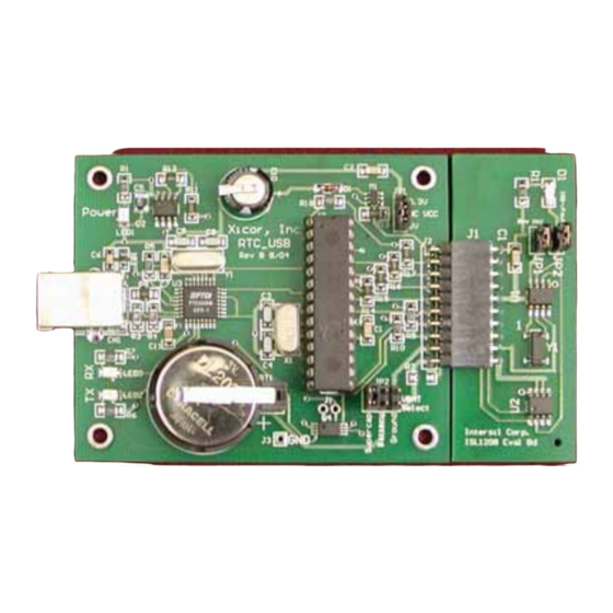
FIGURE 1.
Operation of the RTC Evaluation Board
Hookup and Power
CONNECTIONS
The eval board consists of a motherboard and daughtercard
and these need to be connected together. The evaluation
board uses hardware and software from FTDI for USB
communications and these drivers must be installed on each
PC that talks to the RTC eval board. A USB cable, with type
A and B connectors on the ends, is required to hook up the
board to a PC. The cable should be connected to the PC first
and then to the eval board. Once connected, LED1 will
illuminate indicating +5V power is available from the USB
cable.
POWERING DOWN
The daughter card contains backup power, consisting of a
battery or supercap. When powering down, the
daughtercard will operate off the backup source determined
by JP2 (after the V
voltage discharges from the V
CC
supply capacitors). If the user wishes to totally power down
Real Time Clock USB Evaluation Board
Application Note
CC
1
CAUTION: These devices are sensitive to electrostatic discharge; follow proper IC Handling Procedures.
1-888-INTERSIL or 321-724-7143
June 20, 2005
the RTC device once V
is removed, then either remove
CC
the daughtercard from the motherboard or set JP2 to GND.
Keep in mind there is a decoupling capacitor on the
daughtercard (0.1µF) which must discharge fully before the
RTC device stops operating. This discharge time can be up
to one second when using a V
powered down, the RTC board cannot be monitored by the
RTC software.
Installing the RTC Software and USB Drivers
USB DRIVERS AND COM PORT SETUP
Insert the Intersil RTC_USB CDROM in the PC to be used.
Open the folder "Install USB". Then open the ZIP file
"FTDI.zip". Extract this set of files to a separate folder on
your main hard drive. For example, create a folder titled
"FTDI" on your C: drive, then extract the contents of the ZIP
file to that folder. In the "Install USB" folder, there is a pdf file
titled "Windows Drivers Installation Guide". Open that file
and follow the instructions for the FTDI 232 device (you will
need to connect the RTC_USB Eval Board to your PC's USB
port, this will bring up a prompt to install the USB hardware
and software drivers).
Note that both a hardware AND a software driver need to be
installed for correct USB operation. These are two
procedures that are best done sequentially per the FTDI
Installation Guide.
Once the USB drivers are loaded, locate the RTC program,
titled "Intersil 12xx_2.exe" on the CD. This program can be
placed anywhere on the PC, or may be run from the CD.
Double-click to execute the program (note that the ".._2"
may be changed as the program is updated and the revision
changes).
After starting the program, an error window may appear
indicating that a certain COM port is not available. Dismiss
this window by clicking "OK". A timeout error may follow and
this should be dismissed as well.
On the Intersil RTC Data Analyzer main window, click on the
"Setup" pulldown menu. Click on "Autodetect" and the
program will search each COM port to find which is
connected to the USB device on the eval board. A small
"COM Auto Detect" window will appear and monitor the
polling process. Once the correct COM port is detected, it is
noted in the "COM Auto Detect" window and that window will
close. If you wish to review which COM port is being used,
just click again on the "Setup" pulldown menu.
If no COM port is detected, make sure the board is
connected to the PC with a USB cable and that the board
jumpers are in the appropriate places (see hardware
section). If there is still no COM port detected after any
|
Intersil (and design) is a registered trademark of Intersil Americas Inc.
Copyright © Intersil Americas Inc. 2005. All Rights Reserved.
All other trademarks mentioned are the property of their respective owners.
AN1176.0
of 5V. Note that when
CC
Advertisement

Related Manuals for Intersil ISL1208


Summary of Contents for Intersil ISL1208
- Page 1 The software is designed to allow easy setup and monitoring of all major Insert the Intersil RTC_USB CDROM in the PC to be used. device functions. The two-piece construction utilizing a Open the folder “Install USB”. Then open the ZIP file motherboard and a daughtercard enables the board and “FTDI.zip”.
- Page 2 Application Note 1176 corrections, see the troubleshooting section at the end of The Polling can be turned off by clicking on the polling button this document. again. The RTC device will still be keeping time, and when Polling is turned on again, it will display the RTC current If the COM port number is known in advance (it may be time.
- Page 3 • EEPROM and microprocessor reset (X40411) for storing temperature data. The daughtercard contains the Intersil RTC device, crystal, temperature sensor IC, decoupling capacitor, and pullup resistor for the open drain output. Evaluation Board - Functional Description (see Figure 3 and schematic file RTC_USB_schem.pdf)
-
Page 4: Backup Supply
Pin 10: GND device. There is a dedicated I C serial interface connected This configuration allows these signals to control the Intersil to the Intersil RTC device, EEPROM, and the temperature device on an external board by connecting the serial sensor. - Page 5 OPEN DRAIN OUTPUT will be higher than that without the probe. The open drain output of the ISL1208 is the IRQ-F ISL1209 Daughtercard - Functional Description signal. There is a jumper (JP2) which connects D1 when a...
-
Page 6: Hardware Troubleshooting
Application Note 1176 EVENT INPUT CONTROL BLOCK EVENT INPUT SWITCH EVENT INPUT (ALTERNATIVE) FIGURE 5. ISL1209 DAUGHTERCARD position is unused. Default connection is for a shunt to be open. The event pin needs to be held to ground (normally closed) in order to detect an event. placed across the EVI and GND terminals. - Page 7 6. Talk to an RTC device on a remote board Use the motherboard connector pins and jumper wires to enable ISL1208 or ISL1209 communications with an RTC device on a separate test 1. Set time of day and turn on time and temperature board.
- Page 8 Application Note 1176 Using the RTC-USB Motherboard with 2. Once the software is running, all functions available on the eval board can be used. Note that there is no temp Older X1227 Daughtercards sensor on the X1227 daughtercard, so there is no temp The RTC-USB board is compatible with and can be used monitoring available.
- Page 9 Resistor PIC16C63A SDIP28 PIC 16C63 8-bit Socket 28-DIP x 0.3" Microchip PIC16C63A-04/SP CMOS Microcontroller Through Hole ICL7663CBA LSOIC8 Dual Mode 5V Intersil Programmable Micropower Voltage Regulators FT232BM QUAD32 USB to Serial FTDI FT232BM Converter X40411-A MSOP8 Dual Supply Monitor Intersil...
- Page 10 SE2406CT-ND MC-206 32.768KA-A2 Intersil Corporation reserves the right to make changes in circuit design, software and/or specifications at any time without notice. Accordingly, the reader is cautioned to verify that the Application Note or Technical Brief is current before proceeding.
Need help?
Do you have a question about the ISL1208 and is the answer not in the manual?
Questions and answers