
Subscribe to Our Youtube Channel
Related Manuals for KMART 43203963


Summary of Contents for KMART 43203963
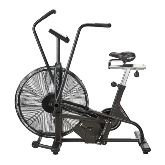
- Page 1 ASSAULT AIR BIKE OWNER’S MANUAL keycode: 43203963 MADE IN CHINA FOR AU/NZ:IMPORTED FOR KMART STORES IN AUSTRALIAAND NEW ZEALAND.
-
Page 2: Important Safety Instructions
IMPORTANT : Read all instructions carefully before using this product. Retain this owner’s manual for future reference. The specifications of this product may vary from this photo, subject to change without notice. IMPORTANT SAFETY INSTRUCTIONS Basic precautions should always be followed, including the following important safety instructions when using this equipment. -
Page 3: Parts List
instructions before using any fitness equipment. CAUTION: Read all instructions carefully before operating this product. Retain this Owner’s Manual for future reference. PARTS LIST Description Description Main Frame Flange Nut M10×1.0 Meter Post Eye Bolt M6x36 Left Handrail Arm Hexagon Nut M10x1.0 Right Handrail Arm Ring Φ10 Handrail... - Page 4 Axle Left Nylon Nut 1/2" Locking Plate Right Nylon Nut 1/2" Bolt M6x10 Ring Φ20 Wave Washer Ф26xФ16x0.3 72 Bearing 6004Z Metal Bushing Ф28xΦ16x16 73 Chain D-shaped Washer Ф28xФ16x5 74 Magnetic Wheel Axle Flat Washer Ф10xФ25x2.0 75 Hexagon Nut M5 Spring Washer Ф19.5xФ11.5x3 76 Spring Washer Ф5 Hexagon Bolt M10x20...
- Page 5 Left Chain Cover Sensor Holder Right Chain Cover Fan Wheel Axle Hexagon Nut M6 Footrest Spring Washer Ф6 End Cap Ф38 T ension Bracket...
-
Page 6: Overview Drawing
OVERVIEW DRAWING... -
Page 7: Hardware & Tools
HARDWARE & TOOLS Spanner with Phillips Screwdriver Spanner S13-S14-S15 S10-S13-S17-S19 Allen Wrench S6 Allen Wrench S5 (29)Carriage Bolt M8×40 4PCS (28) Bolt M10x20 2PCS (30) Curve Washer ø20xø8x1.5 4PCS (31) Cap Nut M8 4PCS (20)Axle 2PCS (27)Spring Washer ø19.5xø11.5x3 2PCS (23)Wave Washer ø26xø16x0.3 2PCS (25)D-shaped Washer (26) Washer... - Page 8 ASSEMBLY INSTRUCTIONS STEP 1:FRONT AND REAR STABILIZER INSTALLATION Remove two M8x16 Hexagon Bolts (15) and two Ф20xФ8x1.5 Flat Washers (38) from the Front Stabilizer (7). Remove bolts with the S6 Allen Wrench provided. Attach the Front Stabilizer (7) onto the Main Frame (1) with removed two M8x16 Hexagon Bolts (15) and two Ф20xФ8x1.5 Flat Washers (38).
- Page 9 STEP 2: HANDRAIL,FOOT BAR AND FOOT PEDAL INSTALLATION Remove four M6x10 Bolts (22) from the Main Frame (1), and take out two Locking Plates (21). Install the Axle (20) to the Main Frame (1), tighten with Spanner provided. Then attach two Locking Plates (21) to the Axle (20) with removed four M6x10 Bolts (22). Tighten with the Allen Wrench S5 provided.
- Page 10 STEP 3: SEAT POST, FOOTREST INSTALLATION Turn the M16x35 Adjustment Knob (81) from the Seat Post (9) in a counterclockwise direction to release the Seat Slider (10). Then attach the Seat Slider (10) back or forth slightly to the desired hole for the suitable position. Lock the Seat Slider (10) in place by tightening M16x35 Adjustment Knob (81) in a clockwise direction.
- Page 11 STEP 4: LEFT AND RIGHT HANDRAIL ARM, METER POST INSTALLATION Insert the Right Handrail Arm (4) on the tube of the Right Handrail (5) with two M8x40 Carriage Bolts (29), two Ф20xФ8x1.5 Curve Washers (30) and two M8 Cap Nuts (31). Repeat the same procedure to assemble the Left Handrail Arm (3).
- Page 12 CLEANING The machine can be cleaned with a soft clean damp cloth. Do not use abrasives or solvents on plastic parts. Please wipe your perspiration off the bike after each use. Be careful not get excessive moisture on the computer display panel as this might cause an electrical hazard or electronics to fail.
- Page 13 BATTERY TYPE 2pcs of SIZE –AAA OPERATING TEMPERATURE 0°C ~ +40°C STORAGE TEMPERATURE -10°C ~ +60°C Note: 1. If the computer displays incorrectly, please re-install the battery and try again. 2. Battery Spec: 1.5V AAA (2PCS). 3. The batteries must be removed from the appliance before it is scrapped and that they are disposed of safety. 4.
Need help?
Do you have a question about the 43203963 and is the answer not in the manual?
Questions and answers