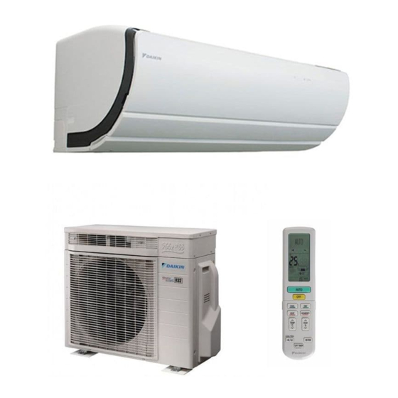
Daikin FTXZ25NV1B Service Manual
Ftxz-n series inverter pair wall mounted type
Hide thumbs
Also See for FTXZ25NV1B:
- Operation manual (48 pages) ,
- Service manual (36 pages) ,
- Installation manual (23 pages)

Related Manuals for Daikin FTXZ25NV1B


Summary of Contents for Daikin FTXZ25NV1B
- Page 1 SiMT041311E Service Manual Inverter Pair Wall Mounted Type FTXZ-N Series [Applied Models] Inverter Pair : Heat Pump...
- Page 2 SiMT041311E Inverter Pair Wall Mounted Type FTXZ-N Series Heat Pump Indoor Unit FTXZ25NV1B FTXZ35NV1B FTXZ50NV1B Outdoor Unit RXZ25NV1B RXZ35NV1B RXZ50NV1B Table of Contents...
-
Page 3: Table Of Contents
SiMT041311E 1. Safety Cautions..................v 1.1 Warnings and Cautions Regarding Safety of Workers......v 1.2 Warnings and Cautions Regarding Safety of Users........ xi 2. Used Icons ................... xiv Part 1 List of Functions ..............1 1. Functions....................2 Part 2 Specifications ..............3 1. - Page 4 SiMT041311E Part 5 Installation / Operation Manual ........57 1. Installation Manual ................58 2. Operation Manual..................77 Part 6 Service Diagnosis............121 1. Service Diagnosis ................123 1.1 Indoor Unit....................123 1.2 Outdoor Unit ..................123 1.3 Remote Controller ................123 2. Troubleshooting ..................125 2.1 Error Codes and Description ..............125 2.2 Air conditioner does not run.
- Page 5 SiMT041311E 2.39 Improper Power Supply Wiring.............178 2.40 Incomplete Setting for Hose Length .............179 2.41 Lights-out of Microcomputer Status Lamp..........180 3. Check ....................181 3.1 Thermistor Resistance Check ..............181 3.2 Fan Motor Connector Output Check ............182 3.3 Humidity Sensor Check................182 3.4 Power Supply Waveforms Check............183 3.5 Electronic Expansion Valve Check............183 3.6 Four Way Valve Performance Check ...........184 3.7 Inverter Unit Refrigerant System Check..........184...
-
Page 6: Safety Cautions
Safety Cautions SiMT041311E 1. Safety Cautions Be sure to read the following safety cautions before conducting repair work. After the repair work is complete, be sure to conduct a test operation to ensure that the equipment operates normally, and explain the cautions for operating the product to the customer. - Page 7 SiMT041311E Safety Cautions Warning Do not start or stop the air conditioner operation by plugging or unplugging the power cable plug. Plugging or unplugging the power cable plug to operate the equipment may cause an electrical shock or fire. Be sure to wear a safety helmet, gloves, and a safety belt when working at a high place (more than 2 m).
- Page 8 Safety Cautions SiMT041311E Caution Use the welder in a well-ventilated place. Using the welder in an enclosed room may cause oxygen deficiency. Checking the area Before beginning work, conduct safety checks to minimise the risk of ignition. When repairing the refrigerating system, take the following precautions before work. Work procedure Work shall be conducted under a controlled procedure so as to minimise the risk of working in the presence of R-32 or vapour.
- Page 9 SiMT041311E Safety Cautions Checking the refrigeration equipment Where electrical components are to be changed, the new components shall be fit for the purpose and have the correct specifications. The manufacturer's maintenance and service guidelines shall be followed at all times. If there are any unclear points, consult the manufacturer's technical department for assistance.
- Page 10 Safety Cautions SiMT041311E Detecting of R-32 Under no circumstances shall potential sources of ignition be used in the search for or detection of refrigerant leaks. A halide torch (or any other detector using a naked flame) shall not be used. Leak detection methods The following leak detection methods can be applied for systems containing R-32.
- Page 11 SiMT041311E Safety Cautions Decommissioning Before carrying out this procedure, it is essential that the technician is completely familiar with the equipment and all its details. It is recommended to train technicians so that all of the refrigerant is recovered safely. In case analysis is required before re-using the reclaimed refrigerant, an oil and refrigerant sample shall be taken before proceeding with decommissioning.
-
Page 12: Warnings And Cautions Regarding Safety Of Users
Safety Cautions SiMT041311E Warnings and Cautions Regarding Safety of Users Warning Do not store the equipment in a room with successive fire sources (e.g., naked flame, gas appliance, electric heater). Be sure to use parts listed in the service parts list of the applicable model and appropriate tools to conduct repair work. - Page 13 SiMT041311E Safety Cautions Warning When relocating the equipment, make sure that the new installation site has sufficient strength to withstand the weight of the equipment. If the installation site does not have sufficient strength and if the installation work is not conducted securely, the equipment may fall and cause injury. Check to make sure that the power cable plug is not dirty or loose, then insert the plug into a power outlet securely.
- Page 14 Safety Cautions SiMT041311E Caution Check the earth / grounding, and repair it if the equipment is not properly earthed / grounded. Improper earth / grounding may cause an electrical shock. Be sure to measure the insulation resistance after the repair, and make sure that the resistance is 1 MΩ...
-
Page 15: Used Icons
SiMT041311E Used Icons 2. Used Icons The following icons are used to attract the attention of the reader to specific information. Icon Type of Description Information Warning A Warning is used when there is danger of personal injury. Warning Caution A Caution is used when there is danger that the reader, through incorrect manipulation, may damage equipment, loose data, get Caution... -
Page 16: Part 1 List Of Functions
SiMT041311E Part 1 List of Functions 1. Functions....................2 List of Functions... -
Page 17: Functions
SiMT041311E Functions 1. Functions Category Functions Category Functions Basic Function PAM control Health and Titanium apatite photocatalytic — Cleanliness air-purifying filter Swing compressor Reluctance DC motor Photocatalytic air-purifying and — deodorising filter Standby electricity saving — Operation URURU HUMIDIFY operation Air filter (pre-filter) SARARA DRY operation Air supply filter... -
Page 18: Part 2 Specifications
SiMT041311E Part 2 Specifications 1. Specifications ..................4 Specifications... -
Page 19: Specifications
SiMT041311E Specifications 1. Specifications 50 Hz, 220 - 230 - 240 V Indoor Unit FTXZ25NV1B FTXZ35NV1B Model RXZ25NV1B RXZ35NV1B Outdoor Unit Cooling Heating Cooling Heating 2.5 (0.6 ~ 3.9) 3.6 (0.6 ~ 7.5) 3.5 (0.6 ~ 5.3) 5.0 (0.6 ~ 9.0) Capacity Rated (Min. - Page 20 Specifications SiMT041311E 50 Hz, 220 - 230 - 240 V Indoor Unit FTXZ50NV1B Model RXZ50NV1B Outdoor Unit Cooling Heating 5.0 (0.6 ~ 5.8) 6.3 (0.6 ~ 9.4) Capacity Rated (Min. ~ Max.) Btu/h 17,100 (2,000 ~ 19,400) 21,500 (2,000 ~ 32,000) kcal/h 4,300 (520 ~ 4,990) 5,420 (520 ~ 8,080)
-
Page 21: Part 3 Printed Circuit Board Connector Wiring Diagram
SiMT041311E Part 3 Printed Circuit Board Connector Wiring Diagram 1. Indoor Unit....................7 2. Outdoor Unit....................9 Printed Circuit Board Connector Wiring Diagram... -
Page 22: Indoor Unit
Indoor Unit SiMT041311E 1. Indoor Unit PCB Detail A1P: Control PCB 1) S21 Connector for centralised control (HA) 2) S32 Connector for indoor heat exchanger thermistor (R1T) 3) S33 Connector for humidity sensor PCB (A4P) 4) S41 Connector for swing motors and humidity sensor PCB (A5P) 5) S44 Connector for brush motor, filter motors, limit switch for brush 6) S46... - Page 23 SiMT041311E Indoor Unit A2P: Signal Receiver / Display PCB 1) S26 Connector for INTELLIGENT EYE sensor PCBs (A6P, A7P) 2) S56 Connector for control PCB (A1P) 3) SW1 (S1W) Forced cooling operation ON/OFF button 4) LED1 (H1P) LED for MOLD PROOF / CLEANING FILTER (green) 5) LED2 (H2P) LED for timer (yellow) 6) LED4 (H4P)
-
Page 24: Outdoor Unit
Outdoor Unit SiMT041311E 2. Outdoor Unit PCB Detail 1) S20 Connector for electronic expansion valve coil 2) S21 Connector for humidifying rotor motor and humidifying thermistor 3) S22 Connector for damper motor 4) S40 Connector for overload protector 5) S45 Connector for thermal fuse (102°C) 6) S70 Connector for DC fan motor... - Page 25 SiMT041311E Outdoor Unit E1, E2 S501 LED A S101 U, V, W HR3, HR4 HR1, HR2 2P345585-2 Printed Circuit Board Connector Wiring Diagram...
-
Page 26: Part 4 Function And Control
SiMT041311E Part 4 Function and Control 1. Main Functions..................12 1.1 Temperature Control ................12 1.2 Frequency Principle................12 1.3 Airflow Direction Control.................14 1.4 Fan Speed Control for Indoor Unit ............18 1.5 Thermostat Control.................19 1.6 URURU HUMIDIFY / HUMID HEATING Operation .......20 1.7 SARARA DRY / DRY COOLING Operation ...........27 1.8 AUTO Operation..................30 1.9 Sensor Operation ...................31 1.10 ECONO / OUTDOOR UNIT QUIET Operation........33... -
Page 27: Main Functions
SiMT041311E Main Functions 1. Main Functions Temperature Control Definitions of The definitions of temperatures are classified as following. Temperatures Room temperature: temperature of lower part of the room Set temperature: temperature set by remote controller Room thermistor temperature: temperature detected by room temperature thermistor Target temperature: temperature determined by microcomputer Target temperature Room thermistor temperature... - Page 28 Main Functions SiMT041311E Drawing of The following drawing shows a schematic view of the inverter principle: Inverter Refrigerant circulation rate (high) high speed Amount of heat Amount of heat exchanged air (large) exchanged air (large) high f low f Amount of heat Amount of heat exchanged air (small) exchanged air (small)
-
Page 29: Airflow Direction Control
SiMT041311E Main Functions Airflow Direction Control Operation Airflow direction (right and left) Airflow direction (up and down) (R19692) ∗ Refer to the operation manual for details. 1.3.1 Auto-Swing Auxiliary flap Main flap Circulation airflow Circulation 0˚ airflow 13˚ 13˚ 17˚ Upper limit of Upper limit of 28˚... - Page 30 Main Functions SiMT041311E 1.3.2 Room Shape and Installation Position Airflow direction is properly controlled by setting the room shape and installation position of the indoor unit in the SET UP menu of the remote controller. The angle of the flap will be set facing higher than the default setting when the room shape is set to horizontal.
- Page 31 SiMT041311E Main Functions Detail COOLING, DRY COOLING • When the up/down airflow direction is set to Circulation, circulation airflow starts. • When the up/down airflow direction is set to AUTO, operation starts in circulation airflow, then switches to BREEZE airflow when the room temperature becomes stable. •...
- Page 32 Main Functions SiMT041311E HEATING, HUMID HEATING When the up/down airflow direction is set to AUTO, if the room temperature is within the zone A - E, circulation airflow starts. If the room temperature is within the zone F - L, comfort airflow starts.
-
Page 33: Fan Speed Control For Indoor Unit
SiMT041311E Main Functions Fan Speed Control for Indoor Unit Outline Phase control and fan speed control contains 9 steps: LLL, LL, SL, L, ML, M, MH, H, and HH. The airflow rate can be automatically controlled depending on the difference between the room thermistor temperature and the target temperature. -
Page 34: Thermostat Control
Main Functions SiMT041311E Thermostat Control Outline Thermostat control is based on the difference between the room thermistor temperature and the target temperature. Detail Thermostat OFF Condition The temperature difference is in the zone A. Thermostat ON Conditions The temperature difference returns to the zone C after being in the zone A. The system resumes from defrost control in any zones except A. -
Page 35: Ururu Humidify / Humid Heating Operation
SiMT041311E Main Functions URURU HUMIDIFY / HUMID HEATING Operation Operation URURU HUMIDIFY HUMID HEATING (R19697) ∗ Refer to the operation manual for details. Features Humidifying method Moisture is taken from the outdoor air with the hygroscopic element mounted in outdoor unit, and sent to indoor. - Page 36 Main Functions SiMT041311E • URURU HUMIDIFY operation This air conditioner enables uniformly humidifying the room by circulating moisture with warm air. The room is uniformly humidified. (R3326) Powerful humidifying ability Model 25 class 35 class 50 class Humidifying capacity 425 ml/h 500 ml/h 600 ml/h The values above are measured at 7°C DB / 6°C WB of outdoor air and with 4 m of...
- Page 37 SiMT041311E Main Functions Conditions for While heating mode, humidifying operation can be available when the following conditions 1 ~ 5 are met at the same time. Humidifying 1. Indoor heat exchanger temperature is 12°C or more. Operation 2. Outdoor temperature is from –10°C to 24°C (meanwhile, in trial operation, up to 34°C is possible).
- Page 38 Main Functions SiMT041311E Humidity At HUMID HEATING operation, as room temperature rises, relative humidity is temporarily lowered. This is because as room temperature rises, relative humidity is lowered even if the Fluctuation by moisture content is the same. Temperature Settings e.g.) The rise in the room temperature from 15°C to 25°C results in the fall in humidity from 40%RH to about 22%RH.
- Page 39 SiMT041311E Main Functions Time chart for Approximately 1 minute after heating operation starts, hose drying operation starts and blows the warmed air into the room at a strong airflow rate, then humidifying operation starts. humidifying operation control Heating operation Residual operation Approx.
- Page 40 Main Functions SiMT041311E Performance The maximum piping length is set to 10 m, but the humidifying capacity varies with the length of the humidifying hose. correction by When the hose length increases by 2 m, the humidifying capacity decreases by about 10%. hose length 120% 100%...
- Page 41 SiMT041311E Main Functions Room humidity (humidity of the discharged air) by outdoor temperature (16 m , hose length: 4 m, ventilation rate: 0.75 times/hour, 25 class) 1. Room temp. 17°CDB 100% Outdoor relative humidity 80%RH 60%RH 40%RH –10 –5 Outdoor temperature (˚C) (R13872) 2.
-
Page 42: Sarara Dry / Dry Cooling Operation
Main Functions SiMT041311E SARARA DRY / DRY COOLING Operation Operation SARARA DRY DRY COOLING (R19699) ∗ Refer to the operation manual for details. Features of SARARA DRY Automatically changes the cooled area of the indoor heat exchanger according to the required dehumidifying amount. - Page 43 SiMT041311E Main Functions Explanation of SARARA DRY Operation with Dehumidifying Psychrometric amount Chart Dry-bulb temperature t (˚C) (R19701) (1) Suction air (2) Suction air (the air passing through the cooled part of indoor heat exchanger) is dehumidified. (3) Dehumidified air is mixed with the room air. Dehumidifying amount Effective airflow rate changes according to the required dehumidifying amount.
- Page 44 Main Functions SiMT041311E MOISTURISING You can select from HI (high), STD (standard), LOW, CONT (continuous), and MOISTURISING. The target humidity cannot be set by %. Setting <Humidity in COOLING / DRY COOLING operation> Humidity % Room humidity MOISTURISING 65% DRY COOLING 50~60% Raise humidity to 65% Rotation speed of indoor unit fan Time...
-
Page 45: Auto Operation
SiMT041311E Main Functions AUTO Operation Operation AUTO (R19702) ∗ Refer to the operation manual for details. Outline Automatic Cooling / Heating Function When the AUTO operation is selected with the remote controller, the microcomputer automatically determines the operation mode as cooling or heating according to the room temperature and the set temperature at start-up. -
Page 46: Sensor Operation
Main Functions SiMT041311E Sensor Operation Operation 3-Area INTELLIGENT EYE / AUTO OFF (R19704) ∗ Refer to the operation manual for details. 1.9.1 3-Area INTELLIGENT EYE Operation Outline The 2 INTELLIGENT EYE sensors detect the presence of the user by dividing the room (sensor range) into 3 areas, to decide whether to blow air directly at or to avoid a person. - Page 47 SiMT041311E Main Functions Detection Method If the sensor detects the outputs 55 times/3 sec. or more, it judges humans are in the room. sampling (20 msec.) 3 sec. High Sensor output Human motion Human detection signal (R19705) • The sensor detects human motion by receiving infrared rays and displays the pulse wave output.
-
Page 48: Econo / Outdoor Unit Quiet Operation
Main Functions SiMT041311E 1.10 ECONO / OUTDOOR UNIT QUIET Operation Operation ECONO / OUTDOOR UNIT QUIET (R19706) ∗ Refer to the operation manual for details. 1.10.1 ECONO Operation • ECONO operation reduces the maximum operating current and the power consumption. This operation is particularly convenient for energy-saving-oriented users. -
Page 49: Powerful Operation
SiMT041311E Main Functions 1.11 POWERFUL Operation Operation POWERFUL (R19707) ∗ Refer to the operation manual for details. Features Operating sound becomes slightly loud. It is impossible to change the airflow rate, temperature, and humidity. The airflow rate and the compressor rotating speed are increased from the normal operation for 20 minutes. -
Page 50: Air Purifying And Ventilation
Operation time (min.) The formaldehyde concentration in the laboratory (10 m ) at 0.5-time natural ventilation and the initial concentration setting of 0.3 ppm (Daikin result) (Nozaki laboratory, Graduate Course of Health and Society System, Tohoku Bunka Gakuen University) (R13882) - Page 51 Ammonia : Pet odour, Bathroom odour Methyl Mercaptane : Garbage odour, Putrid odour Trimethylamine : Fish odour Hydrogen Sulfide : Egg odour Persist rate of odour ingredients in a box of 1m with 50 class model (Daikin result) (R13883) Ammonia Acetaldehyde Acetic Acid...
- Page 52 Main Functions SiMT041311E 3. Controlling temperature The fresh air passed through the air supply filter is cooled (or heated) in the indoor unit and supplied into the room. You can keep comfortable temperature and also replace air because the ventilation is performed while temperature is controlled.
-
Page 53: Mold Proof Operation
SiMT041311E Main Functions 1.13 MOLD PROOF Operation Outline This is an integrated naming of functions of inside drying and moisture exhaustion. Drying inside the air conditioner prevents mold and odors from growing. Operation Automatic or manual operation can be selected. Automatic operation If MOLD PROOF operation is set ON, the MOLD PROOF operation starts automatically after COOLING, SARARA DRY, or COOLING DRY operation. - Page 54 Main Functions SiMT041311E CLEANING FILTER operation (automatic) CLEANING FILTER operation automatically starts when all the below conditions are met. When the 24 HOUR FRESH AIR SUPPLY VENTILATION is on, the unit temporarily suspends the ventilation (closes all the panels and flaps, stops the fan, stops the ventilation) and starts the CLEANING FILTER operation.
-
Page 55: Information
SiMT041311E Main Functions 1.15 INFORMATION Room temperature, indoor humidity, outdoor temperature, and power consumption are displayed. Point the remote controller at the indoor unit for 2 seconds. INFORMATION (R19711) ∗ Refer to the operation manual for details. 1.16 Brightness Setting of Indoor Unit Lamps The brightness of the indoor unit lamps can be adjusted HIGH, LOW, or OFF. -
Page 56: Timer Operation
Main Functions SiMT041311E 1.17 TIMER Operation 1.17.1 ON/OFF TIMER Operation ON/OFF TIMER (R19713) ∗ Refer to the operation manual for details. Features Time can be set in the unit of 10 minutes. When the 24-hour ON/OFF TIMER is set, the indication of present time disappears. Time is kept in memory in the next operation unless it is cancelled. -
Page 57: Comfort Sleep Timer Operation
SiMT041311E Main Functions 1.18 COMFORT SLEEP TIMER Operation COMFORT SLEEP TIMER operation keeps the indoor temperature and humidity at suitable levels for a comfortable sleep and refreshing morning. COMFORT SLEEP TIMER (R19715) ∗ Refer to the operation manual for details. 1.19 QUICK HEATING TIMER Operation Outline QUICK HEATING TIMER operation blows warm air quickly when heating in the morning. -
Page 58: Other Functions
Main Functions SiMT041311E 1.20 Other Functions 1.20.1 Hot-Start Function In order to prevent the cold air blast that normally occurs when heating operation is started, the temperature of the indoor heat exchanger is detected, and the airflow is either stopped or significantly weakened resulting in comfortable heating. -
Page 59: Control Specification
SiMT041311E Control Specification 2. Control Specification Frequency Control Outline The compressor frequency is determined according to the difference between the room thermistor temperature and the target temperature. When the shift of the frequency is less than zero (∆F<0) by PI control, the target frequency is used as the command frequency. - Page 60 Control Specification SiMT041311E When starting the compressor, the frequency is initialised according to the ∆D value of the Initial Frequency indoor unit. <∆D signal: Indoor Frequency Command> The difference between the room thermistor temperature and the target temperature is taken as the ∆D signal and is used for frequency command ∆D ∆D...
-
Page 61: Controls At Mode Changing / Start-Up
SiMT041311E Control Specification Controls at Mode Changing / Start-up 2.2.1 Preheating Control Outline The inverter operation in open phase starts with the conditions of the preheating command from the indoor unit, the outdoor temperature, and the discharge pipe temperature. Preheating control is set to OFF by default. Outdoor temperature ≥... -
Page 62: Compressor Protection Function
Control Specification SiMT041311E 2.2.4 3-Minute Standby Turning on the compressor is prohibited for 3 minutes after turning it off. (The function is not activated when defrosting.) 2.2.5 Compressor Protection Function When turning the compressor from OFF to ON, the upper limit of frequency is set as follows. (The function is not activated when defrosting.) (Hz) Frequency... -
Page 63: Discharge Pipe Temperature Control
SiMT041311E Control Specification Discharge Pipe Temperature Control Outline The discharge pipe temperature is used as the internal temperature of the compressor. If the discharge pipe temperature rises above a certain level, the upper limit of frequency is set to keep the discharge pipe temperature from rising further. Detail Stop zone 115 –... -
Page 64: Input Current Control
Control Specification SiMT041311E Input Current Control Outline The microcomputer calculates the input current while the compressor is running, and sets the frequency upper limit based on the input current. The input current control is the upper limit control of frequency and takes priority over the lower limit control of four way valve operation compensation. -
Page 65: Freeze-Up Protection Control
SiMT041311E Control Specification Freeze-up Protection Control During cooling operation, the signal sent from the indoor unit controls the operating frequency limitation and prevents freezing of the indoor heat exchanger. (The signal from the indoor unit is divided into zones.) Indoor heat exchanger thermistor temperature 13˚C Reset zone... -
Page 66: Draught Prevention Control (Hot-Start Function)
Control Specification SiMT041311E Draught Prevention Control (Hot-Start Function) Outline Draught prevention control prevents cold draught when the unit is started up in heating operation. Detail Draught prevention control is conducted by monitoring the indoor heat exchanger temperature and the set temperature on the remote controller (Ts). When the indoor heat exchanger temperature drops below a certain level or when the Ts exceeds 20°C, the minimum frequency of the compressor increases 4 Hz per 120 seconds. -
Page 67: Dew Prevention Control
SiMT041311E Control Specification Dew Prevention Control Outline Cooling the air around us means that the air is dehumidified (condensation of water on the indoor heat exchanger). But because the air is cooled down, less moisture can present in the air and as a consequence the relative humidity of the air rises. -
Page 68: Defrost Control
Control Specification SiMT041311E 2.10 Defrost Control Outline Defrosting is carried out by the cooling cycle (reverse cycle). The defrosting time or outdoor heat exchanger temperature must be more than a certain value to finish defrosting. Detail Conditions for Starting Defrost The starting conditions are determined with the outdoor temperature and the outdoor heat exchanger temperature. -
Page 69: Electronic Expansion Valve Control
SiMT041311E Control Specification 2.11 Electronic Expansion Valve Control Outline The following items are included in the electronic expansion valve control. Electronic expansion valve is fully closed 1. Electronic expansion valve is fully closed when turning on the power. 2. Pressure equalising control Open Control 1. - Page 70 Control Specification SiMT041311E 2.11.1 Fully Closing with Power ON The electronic expansion valve is initialised when turning on the power. The opening position is set and the pressure is equalised. 2.11.2 Pressure Equalising Control When the compressor is stopped, the pressure equalising control is activated. The electronic expansion valve opens, and develops the pressure equalisation.
- Page 71 SiMT041311E Control Specification 2.11.7 Discharge Pipe Thermistor Disconnection Control Outline The disconnection of the discharge pipe thermistor is detected by comparing the discharge pipe temperature with the condensation temperature. If the discharge pipe thermistor is disconnected, the electronic expansion valve opens according to the outdoor temperature and the operation frequency, operates for a specified time, and then stops.
-
Page 72: Part 5 Installation / Operation Manual
SiMT041311E Part 5 Installation / Operation Manual 1. Installation Manual ................58 2. Operation Manual..................77 Installation / Operation Manual... -
Page 73: Installation Manual
SiMT041311E Installation Manual 1. Installation Manual Safety Precautions Read the precautions in this manual carefully This appliance is filled with R32. before operating the unit. • The precautions described herein are classified as WARNING and CAUTION. They both contain important information regarding safety. Be sure to observe all precautions without fail. -
Page 74: Safety Precautions
Installation Manual SiMT041311E Safety Precautions WARNING • Be sure to earth the air conditioner. Do not earth the unit to a utility pipe, lightning conductor or telephone earth lead. Imperfect earthing may result in electric shocks. • Be sure to install an earth leakage circuit breaker. Failure to install an earth leakage circuit breaker may result in electric shocks or fire. -
Page 75: Choosing An Installation Site
SiMT041311E Installation Manual Accessories Indoor unit Mounting plate Photocatalytic air-purifying and Indoor unit fixing screws deodorising filter (M4 × 12L) Wireless remote controller Remote controller holder Dry batteries AA.LR6 (alkaline) Outdoor unit Humidifying hose (8m) Drain socket Joint Binding bands Operation manual Installation manual •... - Page 76 Installation Manual SiMT041311E Choosing an Installation Site Wireless remote controller (When mounting on a wall etc.) • Turn on all the fluorescent lamps in the room, if any, and find the site where remote control signals are properly received by the indoor unit (within 7m).
- Page 77 SiMT041311E Installation Manual Indoor/Outdoor Unit Installation Drawings How to attach the indoor unit Hook 1) Using the marks (3 locations) on top of the indoor unit, attach the A mounting plate hooks onto the indoor unit. 2) Attach the tabs on the bottom frame onto the A mounting plate. If the tabs are not hooked onto the plate, remove the front grille to hook them.
- Page 78 Installation Manual SiMT041311E Indoor Unit Installation Installing the mounting plate • The mounting plate is located at the back of the indoor unit. Remove a screw. • The mounting plate should be installed on a wall which can support the weight of the indoor unit. 1) Temporarily secure the mounting plate to the wall, make sure that the plate is completely level, and mark the boring points on the wall.
- Page 79 SiMT041311E Installation Manual Humidifying hose installation work 4-1 Connecting to the indoor unit • Connect the cuff side of the humidifying hose to the indoor unit duct. It is easier to connect the hose • Left-side piping with the front grille removed. Insert as far as possible so that there are no gaps.
- Page 80 Installation Manual SiMT041311E Indoor Unit Installation Laying piping, hoses, and wiring • Lay the pipes, drain hose and humidifying hose according Piping bundle diagram to the orientation of the piping coming out of the unit, as shown in the figure. Gas pipe Liquid pipe •...
- Page 81 SiMT041311E Installation Manual 5-3 Wall embedded piping Follow the instructions given under left-side, left-back, or left- Insert drain hose to this bottom piping. depth so it won’t be Inner wall 1) Insert the drain hose to this depth so it won’t be pulled out pulled out of drain pipe.
-
Page 82: Drain Piping
Installation Manual SiMT041311E Indoor Unit Installation Drain piping 1) Connect the drain hose, as described right. The drain hose should be inclined downward. No trap is permitted. Do not put the end of the hose in water. 2) Remove the air filters and pour some water into the drain pan to check the water flows smoothly. - Page 83 SiMT041311E Installation Manual Outdoor Unit Installation Guidelines • Where a wall or other obstacle is in the path of outdoor unit’s intake or exhaust airflow, follow the installation guidelines below. • For any of the below installation patterns, the wall height on the outlet side should be 1200mm or less. Wall facing one side Walls facing two sides Walls facing three sides...
-
Page 84: Refrigerant Piping
Installation Manual SiMT041311E Outdoor Unit Installation Refrigerant piping CAUTION • Use the flare nut fixed to the main unit. (To prevent cracking of the flare nut by aged deterioration.) • To prevent gas leakage, apply refrigeration oil only to the inner surface of the flare. (Use refrigeration oil for R32.) •... - Page 85 SiMT041311E Installation Manual Evacuating the air with a vacuum pump and checking gas leakage WARNING • Do not mix any substance other than the specified refrigerant (R32) into the refrigeration cycle. • When refrigerant gas leaks occur, ventilate the room as soon and as much as possible. •...
- Page 86 Installation Manual SiMT041311E Outdoor Unit Installation Wiring WARNING • Do not use tapped wires, extension cords, or starburst connections, as they may cause overheating, electrical shock, or fire. • Do not use locally purchased electrical parts inside the product. (Do not branch the power for the drain pump, etc., from the terminal block.) Doing so may cause electric shock or fire.
- Page 87 SiMT041311E Installation Manual Connecting the humidifying hose • If the air conditioner is operated without the humidifying hose connected, humidified air fills the outdoor unit and may cause a short-circuit on the printed circuit board. Be sure to connect it. 1) Connect the humidifying hose to the outdoor humidifying duct.
-
Page 88: Installation Tips
Installation Manual SiMT041311E Installation Tips Removing and installing the front panel • Removal method 1) Hook your fingers on both sides of the front panel and open until the panel stops. Pushing further up from the stopping position allows the panel to be removed more easily. 2) While pushing the left side front panel shaft outward, push up the front panel and remove it. - Page 89 SiMT041311E Installation Manual • Installation method Fig. 8 1) Attach the front grille (bottom). Make sure that the tabs on both sides are securely hooked. (See Fig. 8) 2) Attach the service lid and secure it with a screw. 3) Attach the screw cover. 4) Attach the front grilles (left and right) and tighten the mounting screws (2 screws for the left side, 3 for the right side).
- Page 90 Installation Manual SiMT041311E Trial Operation and Testing Setting of the position where the indoor unit is installed • By setting the room shape and the relation with the For details, refer to the operation manual. installation position, proper airflow direction control Left corner for Right corner for Centre for installation...
- Page 91 SiMT041311E Installation Manual 3-3 To perform a trial operation for humidifying operation, activate trial operation mode from the remote controller following the instructions below and press Trial operation from remote controller 1) Press for at least 5 seconds. (The default menu will be displayed.) 2) Press to select “Test mode”...
-
Page 92: Operation Manual
Operation Manual SiMT041311E 2. Operation Manual Safety precautions Read the precautions in this manual carefully This appliance is filled with R32. This appliance is filled with R32. before operating the unit. • Keep this manual where the user can easily find it. •... - Page 93 SiMT041311E Operation Manual • Do not place appliances that produce naked flames in places exposed to the airflow from the unit as this may impair combustion of the burner. • Do not block air inlets nor outlets. Impaired airflow may result in insufficient performance or trouble. •...
- Page 94 Operation Manual SiMT041311E Names and functions of parts Indoor unit Air inlet INTELLIGENT EYE sensor (top surface) Front panel Auxiliary flap Louvres (vertical blades) (horizontal blade) (Inside of the air outlet located on the right and left sides.) Page 13 Page 13 Shutter Flap (horizontal blade)
- Page 95 SiMT041311E Operation Manual When the front panel is open Page 35 Display unit Indoor unit ON/OFF switch • Press to start the operation with the mode set to INTELLIGENT EYE sensor “AUTO” and airflow rate to “AUTO”. Press the button again to stop the operation. Detects human motion to confirm that a person is in •...
- Page 96 Operation Manual SiMT041311E Names and functions of parts Remote controller Transmitter/Receiver Transmitter/Receiver Display (LCD), with backlight • Displays the operating conditions. (All displayed here for your reference.) • Press any of the operation buttons to light the backlight for about 5 seconds. •...
- Page 97 SiMT041311E Operation Manual Open the cover A menu item is shown above. A menu item is shown below. Airflow direction buttons FLASH STREAMER AIR PURIFYING Page 24 Adjust the vertical and horizontal airflow directions. Page 13 FRESH AIR SUPPLY VENTILATION Page 24 1/12 AUTO MOLD PROOF...
-
Page 98: Preparation Before Operation
Operation Manual SiMT041311E Preparation before operation To set the batteries Pull down the upper tab to open the cover. Insert 2 dry batteries AA.LR6 (alkaline). • Using batteries other than AA.LR6 (alkaline) may lead to Upper tab improper operation. Do not confuse Insert the 2 lower tabs on the cover to sides. -
Page 99: To Set The Position Where The Indoor Unit Is Installed
SiMT041311E Operation Manual To set the clock Press Press to set the clock to the current time. • Each time you press , the time changes by 1 minute. If you press and hold the button, the time changes by 10 minutes. -
Page 100: To Set Operation Modes
Operation Manual SiMT041311E To set operation modes AUTO operation To operate in appropriate operation mode (COOLING or HEATING) based on the set temperature and the indoor temperature. Press COOLING operation To lower the temperature. Press “SARARA” DRY operation To lower the humidity. Press DRY COOLING operation To lower the temperature and humidity. - Page 101 SiMT041311E Operation Manual To adjust the temperature Press To adjust the humidity Press Notes on humidity settings Setting Description : MOISTURISING Keeps the humidity high and does not blow air directly on the body to make the operation gentle to your skin.
- Page 102 Operation Manual SiMT041311E To adjust the airflow To adjust the airflow rate Press • Each time you press the button, the airflow rate indicator changes. (Some indicators may not appear depending on the operation mode. Page 14 ..AUTO Indoor unit quiet Airflow rate 1-5 •...
- Page 103 SiMT041311E Operation Manual Notes on airflow rate • When the airflow rate setting is “AUTO”, starting COOLING, “SARARA” DRY, or DRY COOLING operation (including the operation selected with “AUTO”) triggers the deodorising function which reduces odour coming from the indoor unit and the unit does not blow air immediately.
- Page 104 Operation Manual SiMT041311E To adjust the airflow Note on 3-D airflow • Using 3-D airflow circulates cold air, which tends to collect at the bottom of the room, and hot air, which tends to collect near the ceiling, throughout the room, preventing areas of cold and hot developing. Note on horizontal airflow direction •...
-
Page 105: To Operate Wisely Using The Sensor
SiMT041311E Operation Manual To operate wisely using the sensor 3 Area INTELLIGENT EYE operation Whether to blow air away from a person or not can be set according to your preference. The INTELLIGENT EYE sensor detects the movement of a person and automatically changes the airflow direction. -
Page 106: To Use The Timer
Operation Manual SiMT041311E To use the timer ON/OFF TIMER operation This function controls the operation start and stop time. When you set the timer, you can select the operation frequency either once or daily. < To use the operation > Press Press to select the item and press... - Page 107 SiMT041311E Operation Manual COUNTDOWN OFF TIMER operation You can set the timer for the remaining time until the scheduled stop. The timer should be set each time. < To use the operation > Press • The time can be set in increments of 30 minutes each time the button is pressed (from 30 minutes to 9 hours 30 minutes).
-
Page 108: To Ensure A Comfortable Sleep
Operation Manual SiMT041311E To ensure a comfortable sleep COMFORT SLEEP TIMER operation COMFORT SLEEP TIMER operation keeps the indoor temperature and humidity at suitable levels for a comfortable sleep and refreshing morning. < To use the operation > Press during COOLING or HEATING operation. Press to select the item and press 24 HOUR ON TIMER... - Page 109 SiMT041311E Operation Manual Notes on COMFORT SLEEP TIMER operation • When COMFORT SLEEP TIMER is set, the upper limit of the set temperature of HUMID HEATING is 22˚C. • After the COMFORT SLEEP TIMER operation is finished, the operation displayed on the remote controller will continue. •...
-
Page 110: To Guarantee High Heating Capacity When You Wake Up
Operation Manual SiMT041311E To guarantee high heating capacity when you wake up QUICK HEATING TIMER operation This operation quickly blows warm air when the HEATING operation starts in the morning and makes a warm space (warmth zone) around the indoor unit. How to set the QUICK HEATING TIMER Press Press... - Page 111 SiMT041311E Operation Manual < To change or cancel the setting > Follow steps 1 and 2 on page 21 and then select the timer setting you want to change. Press to select the item and press Setting change TIMER cancel •...
-
Page 112: To Increase The Cooling Or Heating Power
Operation Manual SiMT041311E To increase the cooling or heating power POWERFUL operation POWERFUL operation quickly maximises the cooling/heating effect. You can get the maximum capacity. < To use the operation > Press during COOLING or HEATING operation. • When POWERFUL operation is set, the operation mode will be changed as follows. - Page 113 SiMT041311E Operation Manual To purify the air in the room FLASH STREAMER AIR PURIFYING operation Flash streamer discharge decomposes mold and allergic substances to clean the air in the room. FRESH AIR SUPPLY VENTILATION operation The air in the room is cleaned, taking in fresh air from outside. <...
-
Page 114: Econo Operation
Operation Manual SiMT041311E To consider the environment of use ECONO operation ECONO operation enables efficient operation by limiting the maximum power consumption value. This function is useful for ensuring a circuit breaker does not trip when the unit runs alongside other appliances. OUTDOOR UNIT QUIET operation OUTDOOR UNIT QUIET operation lowers the noise level of the outdoor unit by changing the frequency and fan speed on the outdoor... - Page 115 SiMT041311E Operation Manual Notes on ECONO operation < Image of running current and power consumption in ECONO operation > Maximum during normal operation Normal operation Maximum during ECONO operation The maximum running current and power consumption of the air conditioner in ECONO operation vary with the ECONO connecting outdoor unit.
- Page 116 Operation Manual SiMT041311E To keep the air conditioner clean MOLD PROOF operation The inside of the air conditioner is dried to reduce the occurrence of mold and odour. When COOLING, “SARARA” DRY, or DRY COOLING operation is performed, condensation may occur inside the air conditioner and may cause mold or odour. It is recommended to dry the inside of the air conditioner by MOLD PROOF operation.
- Page 117 SiMT041311E Operation Manual CLEANING FILTER operation The air filter will automatically be cleaned. < To automatically operate: Default “On” > Press during operation. • “ ” is displayed on the LCD. • The air filter will automatically be cleaned according to the operating hours (about once per day).
- Page 118 Operation Manual SiMT041311E To keep the air conditioner clean Notes on MOLD PROOF operation • This operation dries the inside of the air conditioner with the FAN ONLY and HEATING operation. • This operation dries the inside of the air conditioner while streamer discharge is performed to reduce the development of mold and odour inside the air conditioner.
- Page 119 SiMT041311E Operation Manual To know the status of your room and air conditioner INFORMATION The indicator displayed on the LCD gives information about temperature, power consumption, and so on. The indicated indoor and outdoor temperatures are measured near the indoor and outdoor units.
- Page 120 Operation Manual SiMT041311E To change the default settings Menu settings You can change the default settings according to your room’s environment and your taste. < To change the setting > 1/12 Press Press to select the item and press Menu items Page INTELLIG.EYE AIRFLOW AUTO OFF time...
- Page 121 SiMT041311E Operation Manual Menu Setting Description The INTELLIGENT EYE sensor detects an area where there is a person and adjusts the Focus horizontal airflow direction to blow air directly on the person. INTELLIG.EYE AIRFLOW The INTELLIGENT EYE sensor detects an area where there is a person and adjusts the Comfort* horizontal airflow direction to avoid blowing air directly on the person.
- Page 122 Operation Manual SiMT041311E To change the default settings Menu Setting Description On * CONTINUE DRY operation is performed. CONTINUE CONTINUE DRY operation is not performed. < Note > • When the indoor temperature or humidity falls far below the preset value, the fans of indoor and outdoor units are stopped to keep the room comfortable.
- Page 123 SiMT041311E Operation Manual Menu Setting Description • You can set the contrast between 1 and 5. CONTRAST 1 to 5 The default setting is “3”. • The higher the figure, the darker the indicator. < Note > • This function sets the contrast of the LCD. Push APPLY Starts 24 HOUR FRESH AIR SUPPLY VENTILATION operation.
- Page 124 Operation Manual SiMT041311E Cleaning (for service personnel) CAUTION • Be sure to stop the operation and turn off the circuit breaker before cleaning. • For care and cleaning, call service personnel. INTELLIGENT EYE sensor Streamer unit Page 36 Front panel Dust box / Dust brush Air supply filter (black) Page 37...
- Page 125 SiMT041311E Operation Manual CAUTION • Do not touch the aluminium fins of the indoor unit. (It may cause an injury.) • Do not use the following to clean the air conditioner. (It may cause deformation, discolouration or scratches.) – Water hotter than 40˚C –...
- Page 126 Operation Manual SiMT041311E Cleaning (for service personnel) Dust box / Dust brush When? < Removing or attaching the dust brush > 1) Pull the centre of the dust brush. When the MOLD PROOF / CLEANING FILTER lamp (green) 2) Take out the dust brush from the right-side and left-side shaft blinks.
- Page 127 SiMT041311E Operation Manual When you clean the filters, open the front panel and remove the dust box. Air filter (white) If the AUTO CLEANING FILTER operation is set to “On”, basically Attaching the air filter no care is required. Page 28 When you are aware of dirt, such as when oil or nicotine is Hold the grips (blue) and insert the attached to the air filter or when the AUTO CLEANING FILTER...
- Page 128 Operation Manual SiMT041311E Cleaning (for service personnel) When you clean the filters, open the front panel and remove the dust box. • Dispose of old filters as non-flammable waste. Photocatalytic air-purifying and • To order a photocatalytic air-purifying and deodorising filter, deodorising filter (black) contact the service shop where you bought the air conditioner.
- Page 129 SiMT041311E Operation Manual When the OPERATION lamp (green) blinks When the OPERATION lamp (green) blinks, turn off the circuit breaker. After about 1 minute, turn it on again and start operation. If the OPERATION lamp still blinks, check the error code according to the steps below and OPERATION lamp (green) take appropriate action.
- Page 130 Operation Manual SiMT041311E Indoor unit Commonly occurring sounds A hissing sound • This is a sound generated when humidified air or ventilated air is discharged. • Operating sound may vary depending on the outdoor temperature or humidity. Roaring sound • This is a sound of ventilating operation. (When ventilating operation is combined with COOLING/HEATING operation, it is possible to stop only ventilating operation.) Page 24...
- Page 131 SiMT041311E Operation Manual Troubleshooting (for service personnel) Before making an inquiry or a request for repair, check the following. If the problem persists, consult the service shop. Not trouble Check These cases are not troubles. Please check again before calling a repair person.
- Page 132 Operation Manual SiMT041311E Troubleshooting (for service personnel) The room does not cool down/warm up Case Description / where to check Air does not come out. In HEATING operation • The air conditioner is warming up. Wait for about 1 to 4 minutes. In COOLING / “SARARA”...
- Page 133 SiMT041311E Operation Manual Remote controller Case Description / where to check The unit does not receive signals • The batteries may be exhausted. from the remote controller or has a Replace all the batteries with new dry batteries AA.LR6 (alkaline). low sensitivity.
- Page 134 Operation Manual SiMT041311E Troubleshooting (for service personnel) CLEANING FILTER operation Case Description / where to check CLEANING FILTER operation does • To protect the air filters, CLEANING FILTER operation is not performed when the indoor not function. temperature is 10˚C or lower. Page 29 •...
-
Page 135: Call The Service Shop Immediately
SiMT041311E Operation Manual Call the service shop immediately WARNING When an abnormality (such as a burning smell) occurs, stop operation and turn the circuit breaker off. • Continued operation in an abnormal condition may result in troubles, electric shocks or fire. •... -
Page 136: Part 6 Service Diagnosis
SiMT041311E Part 6 Service Diagnosis 1. Service Diagnosis ................123 1.1 Indoor Unit....................123 1.2 Outdoor Unit ..................123 1.3 Remote Controller ................123 2. Troubleshooting ..................125 2.1 Error Codes and Description ..............125 2.2 Air conditioner does not run..............126 2.3 Air conditioner runs but does not cool (heat) the room......128 2.4 When operation starts, safety breaker works. - Page 137 SiMT041311E 2.38 Unspecified Voltage (Between Indoor Unit and Outdoor Unit) .....177 2.39 Improper Power Supply Wiring.............178 2.40 Incomplete Setting for Hose Length .............179 2.41 Lights-out of Microcomputer Status Lamp..........180 3. Check ....................181 3.1 Thermistor Resistance Check ..............181 3.2 Fan Motor Connector Output Check ............182 3.3 Humidity Sensor Check................182 3.4 Power Supply Waveforms Check............183 3.5 Electronic Expansion Valve Check............183...
-
Page 138: Service Diagnosis
Service Diagnosis SiMT041311E 1. Service Diagnosis Indoor Unit The operation lamp blinks when any of the following errors is detected. 1. When a protection device of the indoor or outdoor unit is activated, or when the thermistor malfunctions. 2. When a signal transmission error occurs between the indoor and outdoor units. In either case, conduct the diagnostic procedure described in the following pages. - Page 139 SiMT041311E Service Diagnosis Method 2 (1) Open the cover of the remote controller. (2) Press the SET UP button for 5 seconds. (3) Press the button and select Checking error code. (4) Press the APPLY button pointing the remote controller at the indoor unit. (5) The display on the remote controller shows an error code with a long beep.
-
Page 140: Troubleshooting
Troubleshooting SiMT041311E 2. Troubleshooting Error Codes and Description Error Code Unit Description Reference page Air conditioner does not run. Air conditioner runs but does not cool (heat) the room. When operation starts, safety breaker works. Basic Failure Diagnosis Air conditioner makes big noise and vibration. Air is not humidified enough. -
Page 141: Air Conditioner Does Not Run
SiMT041311E Troubleshooting Air conditioner does not run. Supposed Power supply is OFF. Improper power supply voltage Causes Improper connection of wire Incorrect combination of indoor unit and outdoor unit Battery shortage of remote controller Invalid address setting Protection device works (dirty air filter, refrigerant shortage, overfilling, mixed air, etc.) Transmission error between indoor unit and outdoor unit (Defective outdoor unit PCB) - Page 142 Troubleshooting SiMT041311E From the previous page Is the indoor unit Match the compatible compatible with the models. outdoor unit? Make sure that the infrared ray is radiated from remote controller. Is there a sound indicating that a signal Are the batteries in the Replace the batteries.
-
Page 143: Air Conditioner Runs But Does Not Cool (Heat) The Room
SiMT041311E Troubleshooting Air conditioner runs but does not cool (heat) the room. Supposed Refrigerant leakage (Make sure that there is no refrigerant leakage or breaks due to over-tightened flare part.) Causes Improper setting for temperature Incorrect combination of indoor unit and outdoor unit Clogged air filter Insufficient power Refrigerant piping is too long... -
Page 144: When Operation Starts, Safety Breaker Works
Troubleshooting SiMT041311E When operation starts, safety breaker works. Supposed Insufficient capacity of safety breaker Earth leakage breaker is too sensitive. Causes Not exclusive circuit The power supply voltage fluctuation is not within ±10% from the rated value. The size of connecting wire is thin. Air is mixed. -
Page 145: Air Conditioner Makes Big Noise And Vibration
SiMT041311E Troubleshooting Air conditioner makes big noise and vibration. Supposed Refrigerant piping is too short. Mounting wall is too thin. Causes Insufficient vibration prevention measures Deformation of the unit Improper quantity of refrigerant Troubleshooting Be sure to turn off the power switch before connecting or disconnecting Caution connectors, or parts may be damaged. -
Page 146: Air Is Not Humidified Enough
Repair breakage or remove hose? blockage. Is the humidification hose Use the proper hose proper? specified by DAIKIN. Does the outdoor unit suck the Improve so as not to get exhausted air again by short circuit. short circuit? YES (screens, consecutives room ) Is the room ventilated Explain to the user. -
Page 147: Flash Streamer Air Purifying Operation Does Not Run
SiMT041311E Troubleshooting FLASH STREAMER AIR PURIFYING operation does not run. Supposed Front panel is open. Streamer unit cleaning indicator is not reset. Causes Streamer unit is not installed. Dirty streamer unit Dust adheres to the needles of the streamer unit. Broken needles of streamer unit Disconnection of the connector Defective limit switch of the streamer unit... -
Page 148: Intelligent Eye Operation Does Not Run
Troubleshooting SiMT041311E INTELLIGENT EYE operation does not run. Supposed Defective INTELLIGENT EYE sensor unit Disconnection of the harness Causes Dirt on the front panel Dirt on the lens of the INTELLIGENT EYE sensor unit Troubleshooting Be sure to turn off the power switch before connecting or disconnecting Caution connectors, or parts may be damaged. -
Page 149: Indoor Unit Pcb Abnormality
SiMT041311E Troubleshooting Indoor Unit PCB Abnormality Error Code Method of Error The system checks if the circuit works properly within the microcomputer of the indoor unit. Detection Error Decision The system cannot set the internal settings. Conditions Supposed Wrong models interconnected Defective indoor unit PCB (A1P) Causes Disconnection of connector... -
Page 150: Freeze-Up Protection Control / Heating Peak-Cut Control
Troubleshooting SiMT041311E 2.10 Freeze-up Protection Control / Heating Peak-cut Control Error Code Method of Error Freeze-up protection control During cooling operation, the freeze-up protection control (operation halt) is activated Detection according to the temperature detected by the indoor heat exchanger thermistor. Heating peak-cut control During heating operation, the temperature detected by the indoor heat exchanger thermistor is used for the heating peak-cut control (operation halt, outdoor fan stop, etc.) - Page 151 SiMT041311E Troubleshooting Troubleshooting Be sure to turn off the power switch before connecting or disconnecting Caution connectors, or parts may be damaged. Check No.01 Check the air passage. Refer to P.181 Is there any short circuit? Provide sufficient air passage. Check the air filter.
-
Page 152: Fan Motor (Dc Motor) Or Related Abnormality
Troubleshooting SiMT041311E 2.11 Fan Motor (DC Motor) or Related Abnormality Error Code Method of Error The rotation speed detected by the microcomputer during fan motor operation is used to determine abnormal fan motor operation. Detection Error Decision The detected rotation speed is less than 50% of HH tap when the maximum fan motor rotation speed is commanded. - Page 153 SiMT041311E Troubleshooting Troubleshooting Be sure to turn off the power switch before connecting or disconnecting Caution connectors, or parts may be damaged. Check No.02 Refer to P.182 Check the power supply voltage. Is the power supply voltage Correct the power supply. fluctuation within ±10% from the rated value? Note: The motor may break when the...
-
Page 154: Thermistor Or Related Abnormality (Indoor Unit)
Troubleshooting SiMT041311E 2.12 Thermistor or Related Abnormality (Indoor Unit) C4, C9 Error Code Method of Error The temperatures detected by the thermistors determine thermistor errors. Detection Error Decision The thermistor input is 4.96 V and more or 0.04 V and less during compressor operation. Conditions Supposed Disconnection of connector... -
Page 155: Humidity Sensor (For Humidifying) / Humidifying Thermistor Abnormality
SiMT041311E Troubleshooting 2.13 Humidity Sensor (for Humidifying) / Humidifying Thermistor Abnormality Error Code Method of Error The humidity detected by the humidity sensor determine humidity sensor errors. Detection Error Decision The input from the humidity sensor is 4.96 V and more or 0.04 V and less during compressor Conditions operation. -
Page 156: Humidity Sensor (For Room) Abnormality
Troubleshooting SiMT041311E 2.14 Humidity Sensor (for Room) Abnormality Error Code Method of Error Sensor abnormality is detected by input value. Detection Error Decision The input from the humidity sensor is 4.96 V and more or 0.04 V and less. Conditions Supposed Disconnection of connector Defective humidity sensor... -
Page 157: Outdoor Unit Pcb Abnormality
SiMT041311E Troubleshooting 2.15 Outdoor Unit PCB Abnormality Error Code Method of Error Detect within the programme of the microcomputer. Detection Error Decision The programme of the microcomputer is in abnormal running order. Conditions Supposed Defective outdoor unit PCB Noise Causes Momentary drop of voltage Momentary power failure Troubleshooting... -
Page 158: Ol Activation (Compressor Overload)
Troubleshooting SiMT041311E 2.16 OL Activation (Compressor Overload) Error Code Method of Error A compressor overload is detected through compressor OL. Detection Error Decision If the error repeats, the system is shut down. Reset condition: Continuous run for about 60 minutes without any other error Conditions Supposed Disconnection of discharge pipe thermistor... - Page 159 SiMT041311E Troubleshooting Troubleshooting Be sure to turn off the power switch before connecting or disconnecting Caution connectors, or parts may be damaged. Check No.01 Refer to P.181 Discharge pipe thermistor Insert the thermistor in disconnected? position. Check No.12 Refer to P.183 Check No.
-
Page 160: Compressor Lock
Troubleshooting SiMT041311E 2.17 Compressor Lock Error Code Method of Error A compressor lock is detected by checking the compressor running condition through the position detection circuit. Detection Error Decision Operation stops due to overcurrent. If the error repeats, the system is shut down. Conditions Reset condition: Continuous run for about 11 minutes without any other error Supposed... -
Page 161: Dc Fan Lock
SiMT041311E Troubleshooting 2.18 DC Fan Lock Error Code Method of Error An error is determined with the high-voltage fan motor rotation speed detected by the Hall IC. Detection Error Decision The fan does not start in 60 seconds even when the fan motor is running. If the error repeats, the system is shut down. -
Page 162: Input Overcurrent Detection
Troubleshooting SiMT041311E 2.19 Input Overcurrent Detection Error Code Method of Error An input overcurrent is detected by checking the input current value with the compressor running. Detection Error Decision The current exceeds 21 A for 2.5 seconds with the compressor running. (The upper limit of the current decreases when the outdoor temperature exceeds a certain Conditions level.) -
Page 163: Four Way Valve Abnormality
SiMT041311E Troubleshooting 2.20 Four Way Valve Abnormality Error Code Method of Error The room temperature thermistor and the indoor heat exchanger thermistor are checked if they function within their normal ranges in each operation mode. Detection Error Decision A following condition continues over 10 minutes after operating for 5 minutes. Conditions <Cooling / Dry>... - Page 164 Troubleshooting SiMT041311E Troubleshooting Be sure to turn off the power switch before connecting or disconnecting Caution connectors, or parts may be damaged. Check No.01 Four way valve coil Refer to P.181 Correct the four way valve disconnected (loose)? coil. Check No.13 Refer to P.184 Harness out of connector? Reconnect the harness.
-
Page 165: Discharge Pipe Temperature Control
SiMT041311E Troubleshooting 2.21 Discharge Pipe Temperature Control Error Code Method of Error An error is determined with the temperature detected by the discharge pipe thermistor. Detection Error Decision If the temperature detected by the discharge pipe thermistor rises above 115°C, the compressor stops. -
Page 166: High Pressure Control In Cooling
Troubleshooting SiMT041311E 2.22 High Pressure Control in Cooling Error Code Method of Error High-pressure control (operation halt, frequency drop, etc.) is activated in cooling operation if the temperature sensed by the outdoor heat exchanger thermistor exceeds the limit. Detection Error Decision The temperature sensed by the outdoor heat exchanger thermistor rises above about 54.5°C. -
Page 167: Compressor System Sensor Abnormality
SiMT041311E Troubleshooting 2.23 Compressor System Sensor Abnormality Error Code Method of Error The system checks the DC voltage before the compressor starts. Detection Error Decision The voltage converted from the DC current before compressor start-up is out of the range 0.5 ~ 4.5 V. -
Page 168: Power Factor Correction Circuit Abnormality
Troubleshooting SiMT041311E 2.24 Power Factor Correction Circuit Abnormality Error Code Method of Error Overcurrent or overvoltage is detected on power factor correction circuit. Detection Error Decision When the abnormal signal is detected from the power factor correction circuit. Conditions Supposed Defective reactor Reactor harness disconnection or wire breakage Causes... -
Page 169: Position Sensor Abnormality
SiMT041311E Troubleshooting 2.25 Position Sensor Abnormality Error Code Method of Error A compressor start-up failure is detected by checking the compressor running condition through the position detection circuit. Detection Error Decision When the compressor does not run for 15 seconds after receiving operation start command. If the error repeats, the system is shut down. - Page 170 Troubleshooting SiMT041311E Troubleshooting Be sure to turn off the power switch before connecting or disconnecting Caution connectors, or parts may be damaged. Check No.15 Refer to P.185 Turn off the power. Check No.18 Check the power supply voltage. Refer to P.188 Voltage as rated? Correct the power supply.
-
Page 171: Thermistor Or Related Abnormality (Outdoor Unit)
SiMT041311E Troubleshooting 2.26 Thermistor or Related Abnormality (Outdoor Unit) H9, J3, J6, J8, P4 Error Code Method of Error This fault is identified based on the thermistor input voltage to the microcomputer. A thermistor fault is identified based on the temperature sensed by each thermistor. Detection Error Decision The thermistor input voltage is 4.98 V and more or 0.02 V and less for 5 seconds with the... - Page 172 Troubleshooting SiMT041311E Troubleshooting In case of H9, J3, J6, J8 Be sure to turn off the power switch before connecting or disconnecting Caution connectors, or parts may be damaged. Check No.01 Turn on the power again. Refer to P.181 Error displayed Reconnect the connector again on remote and thermistor.
-
Page 173: Electrical Box Temperature Rise
SiMT041311E Troubleshooting 2.27 Electrical Box Temperature Rise Error Code Method of Error An electrical box temperature rise is detected by checking the radiation fin thermistor with the compressor off. Detection Error Decision With the compressor off, the radiation fin temperature is above A°C. The error is cleared when the radiation fin temperature drops below B°C. -
Page 174: Radiation Fin Temperature Rise
Troubleshooting SiMT041311E 2.28 Radiation Fin Temperature Rise Error Code Method of Error A radiation fin temperature rise is detected by checking the radiation fin thermistor with the compressor on. Detection Error Decision The radiation fin temperature with the compressor on is above A°C. The error is cleared when the radiation fin temperature drops below B°C. - Page 175 SiMT041311E Troubleshooting Troubleshooting Be sure to turn off the power switch before connecting or disconnecting Caution connectors, or parts may be damaged. Check No.17 Turn off the power and turn it on Refer to P.188 again to start the system. Check No.19 Has the PCB been Error displayed again?
-
Page 176: Output Overcurrent Detection
Troubleshooting SiMT041311E 2.29 Output Overcurrent Detection Error Code Method of Error An output overcurrent is detected by checking the current that flows in the inverter DC section. Detection Error Decision A position signal error occurs while the compressor is running. A rotation speed error occurs while the compressor is running. - Page 177 SiMT041311E Troubleshooting Troubleshooting Be sure to turn off the power switch before connecting or disconnecting Caution connectors, or parts may be damaged. Check No.15 ∗ An output overcurrent may result from wrong internal wiring. If the system is interrupted by an output Refer to P.185 overcurrent after the wires have been disconnected and reconnected for part replacement, check the wiring again.
-
Page 178: Humidifier Fan Motor System Abnormality / Fan Lock
Troubleshooting SiMT041311E 2.30 Humidifier Fan Motor System Abnormality / Fan Lock Error Code Method of Error During humidifier fan motor running, fan motor system abnormality is identified based on the fan motor rotation speed detected by the Hall IC. Detection Error Decision The fan motor rotation speed does not reach 100 rpm within 12 seconds after starting. -
Page 179: Heater Wire Abnormality
SiMT041311E Troubleshooting 2.31 Heater Wire Abnormality Error Code Method of Error An error is identified when the outlet temperature of humidifying fan does not reach a certain temperature within a given time after the heater is turned on. Detection Error Decision The temperature detected by the humidifying thermistor is lower than the outdoor temperature (with the heater turned off) + 6°C, and this condition continues for 30 minutes. -
Page 180: Humidifying Thermistor Abnormality / Humidifying Heater Temperature Abnormality
Troubleshooting SiMT041311E 2.32 Humidifying Thermistor Abnormality / Humidifying Heater Temperature Abnormality Error Code Method of Error An error is identified when the temperature detected by the humidifying thermistor is abnormal. Detection Error Decision When the power is supplied and the thermistor input is 4.90 V and more or 0.06 V and less. The outlet temperature of humidifying fan is more than 90°C. - Page 181 SiMT041311E Troubleshooting Troubleshooting Be sure to turn off the power switch before connecting or disconnecting Caution connectors, or parts may be damaged. Check the connector for proper Check No.01 connection. Refer to P.181 Reconnect the connector Check No.19 properly. Refer to P.189 Check No.01 Is the resistance of Replace the thermistor.
-
Page 182: Refrigerant Shortage
Troubleshooting SiMT041311E 2.33 Refrigerant Shortage Error Code Method of Error Refrigerant shortage detection I: Refrigerant shortage is detected by checking the input current value and the compressor Detection running frequency. If the refrigerant is short, the input current is lower than the normal value. Refrigerant shortage detection II: Refrigerant shortage is detected by checking the discharge pipe temperature and the opening of the electronic expansion valve. - Page 183 SiMT041311E Troubleshooting Troubleshooting Be sure to turn off the power switch before connecting or disconnecting Caution connectors, or parts may be damaged. Check No.01 Refer to P.181 Any thermistor Replace the thermistor(s) disconnected? position. ∗ Discharge pipe thermistor ∗ Indoor or outdoor heat exchanger thermistor ∗...
-
Page 184: Low-Voltage Detection Or Over-Voltage Detection
Troubleshooting SiMT041311E 2.34 Low-voltage Detection or Over-voltage Detection Error Code Method of Error Indoor Unit Detection The zero-cross detection of the power supply is evaluated by the indoor unit PCB. Outdoor Unit Low-voltage detection: An abnormal voltage drop is detected by the DC voltage detection circuit. Over-voltage detection: An abnormal voltage rise is detected by the over-voltage detection circuit. - Page 185 SiMT041311E Troubleshooting Troubleshooting Be sure to turn off the power switch before connecting or disconnecting Caution connectors, or parts may be damaged. Check the power supply voltage. Is the voltage fluctuation Correct the power supply. within ±10% from the rated value? Check the connection of the compressor harness.
-
Page 186: Signal Transmission Error (Between Indoor Unit And Outdoor Unit)
Troubleshooting SiMT041311E 2.35 Signal Transmission Error (Between Indoor Unit and Outdoor Unit) Error Code Method of Error The data sent from the outdoor unit is checked for problem. Detection Error Decision The data sent from the outdoor unit cannot be received without error, or the disable status of signal transmission continues for 15 seconds. - Page 187 SiMT041311E Troubleshooting Troubleshooting Be sure to turn off the power switch before connecting or disconnecting Caution connectors, or parts may be damaged. Check No.11 Check the connecting wires Refer to P.183 between the indoor unit and the outdoor unit for colour and number.
-
Page 188: Outdoor Unit Pcb Abnormality Or Communication Circuit Abnormality
Troubleshooting SiMT041311E 2.36 Outdoor Unit PCB Abnormality or Communication Circuit Abnormality Error Code Method of Error Detection within the programme of the microcomputer Detection Error Decision The programme of the microcomputer does not work in order. Indoor-outdoor unit signal transmission cannot be performed for more than 15 seconds. Conditions Supposed Power supply voltage is not as specified. - Page 189 SiMT041311E Troubleshooting Troubleshooting Be sure to turn off the power switch before connecting or disconnecting Caution connectors, or parts may be damaged. Check indoor unit also, because a communication circuit fault may be caused by the problem related to the indoor unit. Check the power supply voltage.
- Page 190 Troubleshooting SiMT041311E From the previous page Check No.11 Refer to P.183 Rotate the outdoor fan by hand. Does the outdoor fan Replace the outdoor fan rotate smoothly? motor and outdoor unit PCB. Check No.11 Check the power supply waveform. Locate the cause of the Disturbance? disturbance of the power supply waveform, and...
-
Page 191: Signal Transmission Error On Microcomputer For Humidifying
SiMT041311E Troubleshooting 2.37 Signal Transmission Error on Microcomputer for Humidifying Error Code Method of Error Communication error between microcomputers mounted on the outdoor unit PCB. Detection Error Decision The data sent from the microcomputer for humidifying can not be received for 10 seconds. Zero-cross signal on the microcomputer for humidifying cannot be detected. -
Page 192: Unspecified Voltage (Between Indoor Unit And Outdoor Unit)
Troubleshooting SiMT041311E 2.38 Unspecified Voltage (Between Indoor Unit and Outdoor Unit) Error Code Method of Error Check the incompatible power supply between indoor unit and outdoor unit by using signal transmission. Detection Error Decision In case that the indoor unit model is not compatible with outdoor unit model. Condition Supposed Wrong models interconnected... -
Page 193: Improper Power Supply Wiring
SiMT041311E Troubleshooting 2.39 Improper Power Supply Wiring Error Code Method of Error Check for the incompatible power supply of DC part by using the DC voltage detection circuit. Detection Error Decision The voltage detected by the DC voltage detection circuit is 350 V and more or 180 V and less for more than 1 second. -
Page 194: Incomplete Setting For Hose Length
Troubleshooting SiMT041311E 2.40 Incomplete Setting for Hose Length Error Code Method of Error This fault occurs when the humidification hose length is not stored in the EEPROMs of the indoor unit and the outdoor unit. Detection (Hose length is not stored at initial power on.) Error Decision When the humidification hose length is not stored in EEPROMs of the indoor unit and the outdoor unit. -
Page 195: Lights-Out Of Microcomputer Status Lamp
SiMT041311E Troubleshooting 2.41 Lights-out of Microcomputer Status Lamp Error Code No display Method of Error When a microcomputer fault is detected, LED A turns off. Detection Error Decision Conditions Supposed Outdoor unit PCB is not power supplied. Power supply failure due to noise Causes Troubleshooting Be sure to turn off the power switch before connecting or disconnecting... -
Page 196: Check
Check SiMT041311E 3. Check Thermistor Resistance Check Check No.01 Disconnect the connectors of the thermistors from the PCB, and measure the resistance of each thermistor using a multimeter. The data is for reference purpose only. Thermistor temperature (°C) Resistance (kΩ) –20 197.8 –15... -
Page 197: Fan Motor Connector Output Check
SiMT041311E Check Fan Motor Connector Output Check Check No.02 1. Check the connection of connector. 2. Turn off the power. 3. Check if the resistances between the phases U - V (pins 1 - 7) and between the phases V - W (pins 7 - 4) are 45 ~ 65 Ω respectively. S200 Free pin Phase V... -
Page 198: Power Supply Waveforms Check
Check SiMT041311E Power Supply Waveforms Check Check No.11 Measure the power supply waveform between No. 1 and No. 2 on the terminal board, and check the waveform disturbance. Check if the power supply waveform is a sine wave. (Fig.1) Check if there is waveform disturbance near the zero cross. (sections circled in Fig.2) Fig.1 Fig.2 (R1444) -
Page 199: Four Way Valve Performance Check
SiMT041311E Check Four Way Valve Performance Check Check No.13 < Caution on resetting the power supply > ∗ Be sure to wait for 30 sec. or more after turning off the power. Turn off the power and turn it on again. -
Page 200: Inverter Analyser Check
Check SiMT041311E Inverter Analyser Check Check No.15 Characteristics Inverter analyser: RSUK0917C If an abnormal stop occurs due to compressor startup failure or overcurrent output when using an inverter unit, it is difficult to judge whether the stop is caused by the compressor failure or some other failure (main PCB, power module, etc.). - Page 201 SiMT041311E Check (2) Open the cover. (R20203) Diagnose method (Diagnose according to 6 LEDs lighting status.) (1) If all the LEDs are lit uniformly, the compressor is defective. → Replace the compressor. (2) If the LEDs are not lit uniformly, check the power module. →...
-
Page 202: Rotating Pulse Check On Outdoor Unit Pcb
Check SiMT041311E Rotating Pulse Check on Outdoor Unit PCB Check No.16 Outdoor fan motor: S70 Humidifier fan motor: S72 Make sure that the voltage of 320 ± 30 V is applied. 1. Set operation off and power off. Disconnect the connector S70 or S72. 2. -
Page 203: Installation Condition Check
SiMT041311E Check 3.10 Installation Condition Check Check No.17 Installation condition check Check the allowable dimensions of the air Change the installation suction and location or direction. discharge area. Is the discharged air Change the installation short-circuited? location or direction. Is the outdoor heat Clean the outdoor heat exchanger very dirty? exchanger. -
Page 204: Outdoor Fan System Check
Check SiMT041311E 3.12 Outdoor Fan System Check Check No.19 DC motor Check the outdoor fan system. Fan motor lead wire connector Outdoor fan running? Go to Check No. 16. disconnected? Reconnect the connector. Outdoor fan system is functioning. (R19395) 3.13 Main Circuit Short Check Check No.20 Note: Check to make sure that the voltage between (+) and (–) of the diode bridge (DB1) is... -
Page 205: Power Module Check
SiMT041311E Check 3.14 Power Module Check Check No.22 Note: Check to make sure that the voltage between (+) and (–) of the diode bridge (DB1) is approximately 0 V before checking. Disconnect the compressor harness connector from the outdoor unit PCB. To disengage the connector, press the protrusion on the connector. -
Page 206: Part 7 Tips For Servicing
SiMT041311E Part 7 Tips for Servicing 1. Tips for Servicing ................192 1.1 Pump Down Operation .................192 1.2 Forced Cooling Operation ..............192 2. Trial Operation ..................193 3. Field Settings ..................194 3.1 SET UP Menu ..................194 3.2 Service Setting Menu ................194 3.3 Humidifying Hose Length Setting ............197 4. -
Page 207: Tips For Servicing
SiMT041311E Tips for Servicing 1. Tips for Servicing Pump Down Operation Outline In order to protect the environment, be sure to conduct pump down operation when relocating or disposing the unit. Detail 1) Remove the valve caps from the liquid stop valve and the gas stop valve. 2) Carry out forced cooling operation. -
Page 208: Trial Operation
Trial Operation SiMT041311E 2. Trial Operation Outline Carry out the trial operation in accordance with the operation manual to ensure that all functions and parts, such as flap movement, are working properly. Trial operation should be carried out in either cooling or heating operation. Detail 1. -
Page 209: Field Settings
SiMT041311E Field Settings 3. Field Settings SET UP Menu You can change the default settings according to your room’s environment. Menu items INTELLIG.EYE AIRFLOW AUTO OFF time BREEZE AIRFLOW HUMIDIFY AIRFLOW CONTINUE DRY INSTALLED POSITION RESET USED POWER SOUND VOLUME CONTRAST 24 HOUR FRESH AIR RC ADDRESS... - Page 210 Field Settings SiMT041311E 3. Hose length It sets the length of the humidifying hose. The longer the length setting is, the higher the humidifying fan rotation frequency becomes. 4. Hose drying It forces to turn on the humidifying fan and dries the inside of the humidifying hose. Forced hose drying operation lasts about 30 minutes.
- Page 211 SiMT041311E Field Settings 19.Auto clean speed It sets the operation time for cleaning filter. If it is set to Fast, the cleaning time is about 7 minutes. 20.RESET setting It resets the SET UP menu and service setting menu to factory setting. Note Note for replacing the indoor unit PCB When the indoor unit PCB is replaced, all the settings are reset and have to be set on the...
-
Page 212: Humidifying Hose Length Setting
Field Settings SiMT041311E Humidifying Hose Length Setting Outline Set the humidifying hose length with the remote controller to ensure humidifying capacity. Power on the indoor unit to establish the communication between the indoor unit and the remote controller. (The humidifying hose length includes the rear part of the indoor unit.) Detail (1) Open the cover of the remote controller. -
Page 213: Silicon Grease On Power Transistor / Diode Bridge
SiMT041311E Silicon Grease on Power Transistor / Diode Bridge 4. Silicon Grease on Power Transistor / Diode Bridge Outline Apply the specified silicon grease to the heat radiation part of a power transistor / diode bridge when you replace an outdoor unit PCB. The silicon grease encourages the heat radiation of a power transistor / diode bridge. -
Page 214: Part 8 Appendix
SiMT041311E Part 8 Appendix 1. Piping Diagrams..................200 1.1 Indoor Unit....................200 1.2 Outdoor Unit ..................200 2. Wiring Diagrams..................201 2.1 Indoor Unit....................201 2.2 Outdoor Unit ..................201 Appendix... -
Page 215: Piping Diagrams
SiMT041311E Piping Diagrams 1. Piping Diagrams Indoor Unit FTXZ25/35/50NV1B INDOOR UNIT HEAT EXCHANGER HEAT EXCH. CROSS FLOW FAN THERMISTOR FAN MOTOR FIELD PIPING ( 6.4 CuT ) SINGLE UNION JOINT 9.5 CuT FIELD PIPING ( 9.5 CuT ) SINGLE UNION JOINT HUMIDITY SENSOR ROOM TEMPERATURE ( OUTER AIR ) -
Page 216: Wiring Diagrams
Wiring Diagrams SiMT041311E 2. Wiring Diagrams Indoor Unit FTXZ25/35/50NV1B CAUTION NOTE THAT OPERATION WILL RESTART AUTOMATICALLY IF THE MAIN POWER SUPPLY IS TURNED OFF AND THEN BACK A5P R3T ON AGAIN. OUTDOOR FIELD WIRING. A1P~A7P : PRINTED CIRCUIT BOARD t˚ C104, C105 : CAPACITOR HUMIDITY... - Page 217 Revision History Month / Year Version Revised contents 03 / 2014 SiMT041311E First edition...
- Page 218 Improper installation can result in water or refrigerant leakage, electrical shock, fire or explosion. Use only those parts and accessories supplied or specified by Daikin. Ask a qualified installer or contractor to install those parts and accessories. Use of unauthorised parts and accessories or improper installation of parts and accessories can result in water or refrigerant leakage, electrical shock, fire or explosion.
Need help?
Do you have a question about the FTXZ25NV1B and is the answer not in the manual?
Questions and answers