Table of Contents
Advertisement
Advertisement
Table of Contents

Related Manuals for HBS ONURFIX A 12


Summary of Contents for HBS ONURFIX A 12
- Page 1 A 12 Welding Gun 93-20-270 Operating Manual...
- Page 2 Customer Service in Germany: HBS Bolzenschweiss-Systeme GmbH & Co. KG Felix-Wankel-Strasse 18 85221 Dachau / Germany Phone +49 (0) 8131 511-0 +49 (0) 8131 511-100 E-mail post@hbs-info.com www.hbs-info.com A 12 Operating Manual, Issue 03/2008 Order No. BA 93-20-270 Copyright: The information contained herein may not be copied, reproduced, adapted, merged, translated or used without the prior written consent of the copyright owner.
- Page 3 stud welding units can be dangerous to life. For your own sake you should know the safety instructions for operating your HBS stud welding units inside out.
- Page 4 If you should detect errors or mistakes right in this manual, please contact us: HBS Bolzenschweiss-Systeme GmbH & Co. KG Felix-Wankel-Strasse 18 85221 Dachau / Germany A feedback blank is provided in the appendix.
-
Page 5: Table Of Contents
Table of Contents Table of Contents General ..................... 7 Guide to this Operating Manual ..............8 Safety Symbols .................... 9 General Safety Instructions ................ 10 Intended Use ....................10 Transportation, Packaging, Storage ............11 Accompanying Documents ................ 11 Markings ..................... 12 Delivery ................... - Page 6 Table of Contents Checking the Quality of the Weld ............... 32 5.7.1 Visual Inspection ....................32 5.7.2 Bending Test ......................33 5.7.3 Arc Blow Effect ...................... 35 Malfunctions and Corrective Actions ............36 Welding Elements ..................37 Switching off the Welding Gun ............. 40 Temporary Switching off ................
-
Page 7: General
General Persons addressed by this operating manual This operating manual is written for operators, personnel of the end user, and authorized service technicians. It provides you with all necessary information to operate the welding gun. Required user qualification The welding gun must only be operated by qualified personnel. Let the welding gun only be operated by persons who –... -
Page 8: Guide To This Operating Manual
Guide to this Operating Manual This operating manual provides you with the following information "Delivery" in Chapter 2 "Starting-up" in Chapter 3 "Functional Principle" in Chapter 4 "Stud Welding Process" in Chapter 5 "Switching off the Welding Gun" in Chapter 6 "Care and Maintenance"... -
Page 9: Safety Symbols
Safety Symbols Symbols and markings used in this operating manual mean: Threat to life or risk of personal injury Risk of material damage Ban for persons fitted with a pace maker Warning of dangerous electrical voltage Warning of electromagnetic fields Wear protective clothes Wear protective goggles Wear ear protection... -
Page 10: General Safety Instructions
(place of operation see section 8.1). The welding gun A 12 can be connected to the HBS power units ARC 500, ARC 800, ARC 1550, IT 90, IT 130, IT 1001 and IT 2001. For details please contact the HBS customer service (address see page ii). -
Page 11: Transportation, Packaging, Storage
Transportation, Packaging, Storage HBS delivers products in a specific transport package. Save the undamaged packing. Ship and transport the device only in its original packing. Right before delivery, the welding gun is once again checked for proper functioning and a control mark is attached. When receiving the delivery, check everything for damages and completeness. -
Page 12: Markings
Markings There are various markings and safety symbols attached to your power unit (see section 8.1). Make sure that all markings remain clearly visible. Type plate The type plate contains the following data: Manufacturer Type Order No./Serial No. Primary voltage Fuse Power consumption Cooling class... -
Page 13: Delivery
Delivery The basic equipment of your welding gun contains the following components: No. of pieces Part Type Order No. Welding gun, cable length 5 m A 12 93-20-270 Operating Manual A 12 BA 93-20-270 A 12 Order No. BA 93-20-270 Issue 01.03.08... -
Page 14: Starting-Up
Starting-up In this chapter you learn what to observe during setting-up and starting-up of the welding gun. Requirements of Workplace The welding gun corresponds with protection class IP 20. It must not be used in a humid environment! Vapors and airborne particles may occur during stud welding operations. -
Page 15: Connecting The Welding Gun To The Power Unit
Secure the following safety symbols in the area of welding place: THREAT TO LIFE to persons fitted with a pace maker Strong electro-magnetic fields occur in the vicinity of the stud welding unit during welding. Such fields may affect the proper function of a pace maker. -
Page 16: Ground Connection
Plug in the control cable of the welding gun into the appropriate connection on the power unit. Twist the retaining nut of the control cable connector clockwise to secure the connection. The welding gun cables must not be coiled during welding. Coiled cables work as a coil and may negatively affect the welding result. -
Page 17: Change Working Place
Connect the ground clamps to the workpiece as securely as possible. Take care to ensure good contact and symmetrical connection. The welding location must lie directly between the two ground clamps. Change Working Place Switch off the power unit. In this way, you avoid any risk of electrical shock. -
Page 18: Function
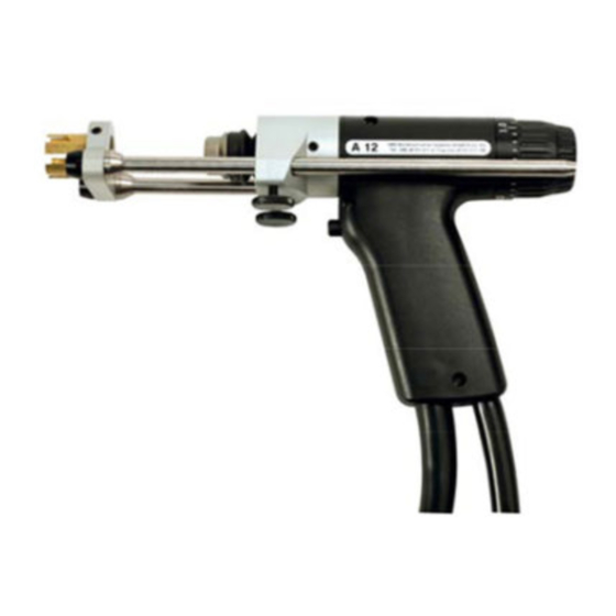
Function In this chapter you learn more about the design of the welding gun and how to use the various setting options. Components of the Welding Gun Ceramic The body of the welding gun consists of a sturdy two-part plastic housing (2). -
Page 19: Adjustment Of Projection (Plunging Depth)
Adjustment of Projection (Plunging Depth) Set the burnoff (plunging distance, projection). You will find reference values in the operating manual of the power unit used. Clamp the tripod column with the knurled screws. Adjustment of Lift Draw the adjustment wheel backwards out of its locking position. By rotating the adjustment wheel counter-clockwise, you can adjust... - Page 20 The adjustment wheel can be turned by max. 360°. Forced turning with noticeable resistance of the adjustment wheel can result in mechanical damage of components. You can take reference values of the welding parameters to be adjusted, like welding current and welding time, from the operating manual of the welding power unit to which the stud welding gun A 12 is connected.
-
Page 21: Stud Welding Procedure
Stud Welding Procedure This chapter contains the basics of welding, how you must actually proceed, and what must be observed. You learn to select correct welding parameters and which welding elements can be used. Safety Instructions Improper operation of the stud welding unit is LIFE-THREATENING ! Threat to life by electric shock and arc... - Page 22 THREAT TO LIFE by toxic vapors and airborne particles Toxic vapors and airborne particles may occur during stud welding operations, especially with surface treated materials. Ensure that a fume extraction is available that the room is adequately ventilated according to accident prevention regulations. If possible, do not weld in rooms which are lower than 3 meters.
- Page 23 stud welding unit are prohibited and result in complete cancellation of any guarantee and liability claims against HBS. In case of any accidents whatsoever, advise a physician, your supervisor, and the official bodies immediately.
-
Page 24: Functional Principle Of Stud Welding
Drawn-Arc Stud Welding The HBS stud welding unit operates by process of ‘arc stud welding with drawn-arc ignition’ according to the current standards (see appendix). The standards assign this method of joining pin-shaped elements with plane workpieces to the so called ‘Arc Pressure Welding’... - Page 25 – The main arc burns at the set current during the welding time preselected at the power unit. The selected welding energy must match the requirements of the selected welding element. The energy of the arc melts the face of the welding element and the workpiece (see position 3).
-
Page 26: Drawn-Arc Stud Welding With Ceramic Ferrule
5.2.1 Drawn-Arc Stud Welding with Ceramic Ferrule Drawn-arc stud welding with ceramic ferrule is used with welding elements of 3 to 25 mm diameter (preferably above 12 mm diameter) and with welding times of 50 to 2000 ms. It is generally suitable for all welding positions. When stud welding with ceramic ferrule, the welding position is PA (vertical). -
Page 27: Short-Cycle Drawn-Arc Stud Welding With Shielding Gas
The shielding gas influences – the arc and the melting behavior of welding element and workpiece, – the development of the weld collar and the penetration shape via the surface tension. With stud welding with shielding gas, the shape of the weld collar is not reproducible, as the shielding gas has no forming effects on the melt –... -
Page 28: Drawn-Arc Capacitor-Discharge Stud Welding
5.2.4 Drawn-Arc Capacitor-Discharge Stud Welding With drawn-arc capacitor-discharge stud welding, the welding energy is taken from a capacitor. As a result, welding currents are very high and welding times (< 10 ms) very short. Normally, a weld pool protection is not required. The process is mainly used for welding elements in a diameter range of up to 8 mm. -
Page 29: Determination Of Welding Parameters
Determination of Welding Parameters The adjustment of welding parameters on the power unit (e.g. welding time) or on the welding gun (e.g. lift) depends amongst others on – material of the welding element – diameter of the welding element – material of the workpiece The guidelines should be verified by test... - Page 30 Setting of welding gun A 12 Preferably under shielding gas Preferably with ceramic ferrule Welding element with Welding element with conical face conical or plane face Eff. diameter Plunging depth Lift Plunging depth Lift (metric/mm) (imperial) #4 or 12 gage #10 or 3/16"...
-
Page 31: Welding Procedure
Welding Procedure Improper operation of the stud welding unit is LIFE-THREATENING! The stud welding unit must only be operated by qualified personnel (see chapter 1). Observe the safety instructions in chapters 1, 3 and 5. Prepare the stud welding unit, the ground connection, and the workpiece according to the instructions given in the operating manual. -
Page 32: Checking The Quality Of The Weld
Checking the Quality of the Weld You can check the quality of the weld by means of a visual inspection and a bending test. See also actual standards in the appendix “Arc stud welding of metallic materials“, in section irregularities and corrective actions. -
Page 33: Bending Test
5.7.2 Bending Test You can purchase from HBS a bending device with inserts for various diameters of the welding elements. The bending test serves as an easy work sample and as a check for the selected welding parameters. The welded joint is stressed by bending in a non-defined way. - Page 34 Bending Test Type of fracture Possible cause Corrective actions Base material buckling - Correct parameters - none Fracture in welding element - Correct parameters - none above weld collar Fracture in the weld metal - Welding energy too low - Increase welding energy Many pores - Plunging speed too low - Increase plunging speed...
-
Page 35: Arc Blow Effect
5.7.3 Arc Blow Effect A so called arc blow effect can occur with unproportionally distributed ground connec- tions in relation to the base material mass, varying material distribution, or welding at the edge of a workpiece. This is an undesired deflection of the arc. It causes a single- sided melting of the stud material, increased pore formation, and undercuts in the welding area. -
Page 36: Malfunctions And Corrective Actions
5 Stud Welding Procedure 5.8 Malfunctions and Corrective Actions Malfunctions and Corrective Actions Malfunction Possible cause Fault finding Corrective action Carried out by Welding elements Wrong w elding Check the adjusted Change adjusted Instructed personnel not firmly attached parameters selected w elding time and/or parameters w elding current on the... -
Page 37: Welding Elements
Welding Elements The stud welding unit must be suitable for welding the welding elements to be used. Observe the instructions in the operating manuals. Welding elements are mainly manufactured with the cold formed process. We recommend the following standard welding elements (see appendix). Use only welding elements of the same lot. - Page 38 Pin UD (S) Diameter Length Chuck Ceramic Shielding gas *) 20-50 mm 83-50-006 83-51-006 20-50 mm 83-50-008 83-51-008 20-80 mm 83-50-010 83-51-010 20-80 mm 83-50-012 83-51-012 25-80 mm 83-50-016 Materials: S235 / St37.3k (4.8) / 1.4301, 1.4303 Pin with internal thread MI (ID) Diameter Length Chuck Ceramic...
- Page 39 82-50-006 Materials: S235 / St37.3k (4.8) / 1.4301, 1.4303 We look forward to consult you with view to special welding elements and other special materials. HBS Bolzenschweiss-Systeme GmbH & Co. KG Felix-Wankel-Strasse 18 85221 Dachau / Germany Phone +49 (0) 8131 511-0...
-
Page 40: Switching Off The Welding Gun
Protect the stud welding gun against ingress of fluids and foreign bodies. Disposal If you shut down the installation, you can return the complete welding gun to HBS (for address see page ii). We will take care for environmentally correct material separation and disposal. -
Page 41: Care And Maintenance
Care and Maintenance This chapter shows care and maintanance of the welding gun to provide long life expectancy. Safety Instructions Let maintenance and repair operations be carried out only by qualified personnel or by your competent service technician. Before you start any cleaning and maintenance operation with the welding gun, always switch the power unit off... -
Page 42: Regular Maintenance Operations
Regular Maintenance Operations Any maintenance and repair operation should only be carried out by qualified personnel or by your competent service techni- cian. You must only carry out the following service operations. Before starting welding, check welding cable and control cable for faults and damage. -
Page 43: Appendix
Appendix In the appendix, there is information of interest regarding technical data, spare part lists, accessories, standards etc. Technical Data Stud Welding Gun A 12 for ARC stud welding according to current standards M 12, dia. 3 to 12 mm (#4 to 1/2”, dia. -
Page 44: Spare Parts
Spare Parts Spare part list welding gun type A 12 (93-20-270) When ordering spare parts, please indicate order number and type of welding gun. The type is to be found at the housing. Pos. Quantity Order No. Description 88-10-673B Basic shell, complete 80-09-045 Cover shell 80-11-270... - Page 45 Welding gun type A 12 (93-20-270) A 12 Order No. BA 93-20-270 Issue 01.03.08...
- Page 46 Spare part list shielding gas tripod complete, A 12 (93-40-021) Pos. Quantity Order No. Description 80-40-149 Gas foot piece 80-40-538 Foot piece 80-10-113 Bellows holder-G 80-10-176 Bellows 80-40-411 Leg 8-220 80-40-531 Cover plate tripod 5.5 m 80-11-420 Plastic hose 80-10-024 Nipple 80-10-139 Connector male...
- Page 47 Shielding gas tripod complete, A 12 (93-40-021) A 12 Order No. BA 93-20-270 Issue 01.03.08...
- Page 48 Spare part list ceramic tripod complete, A 12 (93-40-022) Pos. Quantity Order No. Description 80-40-531 Cover plate tripod 80-40-410 Foot piece alu 80-40-411 Leg 8-220 80-90-124 Screw M5 x 6 80-90-126 Screw M5 x 25 A 12 Order No. BA 93-20-270 Issue 01.03.08...
- Page 49 Ceramic tripod complete, A 12 (93-40-022) A 12 Order No. BA 93-20-270 Issue 01.03.08...
-
Page 50: Accessories
Accessories When ordering accessories, please indicate order number and type of welding gun. Description Order No. ------------------------------------------------------------------------------------------------------------------------ Adapter Standard for ARC 80-05-689 Welding with ceramic ferrules: Chuck Threaded studs, sleeves with internal thread and pins Ø 5 mm e 6 mm 83-50-005 Ø... - Page 51 Welding with ceramic ferrules: ------------------------------------------------------------------------------------------------------------------------------------------------------------------ Threaded studs, Chuck ceramic ferrules sleeves with internal thread and pins for stud-Ø Ø Ø Ø 6 mm 80-31-095 Ø 8 mm 80-31-120 Ø 10 mm 80-31-150 Ø 12 mm MR 80-31-170 Ø 12 mm MD 80-31-205 larger Ø...
-
Page 52: Environmentally Admissible Disposal
Environmentally Admissible Disposal After repair of the welding gun, dispose the replaced parts in an environmentally admissible way. Used materials: Steel Non ferrous metals (brass, copper) Plastics Aluminium A 12 Order No. BA 93-20-270 Issue 01.03.08... -
Page 53: Glossary
Glossary Arc: Electrical discharge at its own between two electrodes under sufficiently high current. Whitish light is emitted. The arc generates very high temperatures. Automatic welding head: Device to weld welding elements Capacitor: A component which serves as storage of electrical charge Power unit: Device to provide electrical energy for stud welding... -
Page 54: Regulations And Standards
Regulations and Standards The regulations and standards are recommendations and don`t purport to be completely. Standards, regulations Description Stud welding (fundamentals) DIN EN ISO 13918 Welding - Studs and ceramic ferrules for arc stud welding DIN EN ISO 14555 Welding - Arc stud welding of metallic materials DIN EN 1418 Welding personnel - Approval testing of welding operators for fusion welding and resistance weld... - Page 55 Machine safety 2006/95/EC Electrical equipment designed for use within certain voltage limits 2004/108/EC EMC-Guidelines 98/37/EC Machine guideline (valid until 28.12.2009) 2006/42/EC Machine guideline (valid from 29.12.2009) DIN EN 60204-1 Safety of machinery - Electrical equipment of machines - Part 1: General requirements DIN EN 60529 Degrees of protection provided by enclosures (IP code)
-
Page 56: Further Instructions
Further Instructions Welding elements, abbreviations, materials, standards, mechanical properties to actual standards Abbreviations for Mechanical Stud types studs (ceramic Material Norm characteristics ferrules) Threaded stud PD (PF) Mild steel (4.8 ISO 898-1 see ISO 898-1 Threaded stud w ith reduced RD (RF) shaft Draw n arc... -
Page 57: Guarantee Clauses
Warning: Unauthorized interference with the stud welding unit as well as unauthorized alteration of the stud welding unit are prohibited and result in complete cancellation of any guarantee and liability claims against HBS. Please fill in the serial number: Serial number automatic welding head: .......... -
Page 58: Eu-Statement Of Conformity
This is to certify, that equipment listed below is designed and manufactured in conformance to the safety and health regulations. This statement is invalid if any modifications are done on the equipment without prior written approval by HBS. Description of equipment: Welding Gun Type:... -
Page 59: Confirmation
Confirmation Herewith I confirm that I have read and understand the present operating manual completely. Date Name ________________ ___________________________________ ________________ ___________________________________ ________________ ___________________________________ ________________ ___________________________________ ________________ ___________________________________ ________________ ___________________________________ ________________ ___________________________________ ________________ ___________________________________ ________________ ___________________________________ ________________ ___________________________________ ________________ ___________________________________ ________________ ___________________________________ ________________ ___________________________________... -
Page 60: Feedback
Feedback HBS Bolzenschweiss-Systeme Sender: GmbH & Co. KG __________________________ Felix-Wankel-Strasse 18 __________________________ 85221 Dachau / Germany __________________________ Postfach 13 46 __________________________ 85203 Dachau / Germany __________________________ Product description __________________________ Serial number __________________________ My opinion/criticism/complaints/indication of malfunction: Date and signature ___________________________________________... -
Page 61: Service & Support
Service & Support A 12 Order No. BA 93-20-270 Issue 01.03.08... -
Page 62: Index
Index dirt and dust ........42 disposal ......... 40, 52 accessories ......... 50 disposal, environmentally admissible ... 52 accident prevention ......10, 22 distance device ........31 accident prevention regulations .... 14 drawn-arc stud welding, variations ..25 accidents ..........23 DVS regulations ........ - Page 63 high-strength welds ......28 pipes, welding to ......... 28 hollow parts, welding on ...... 22 place of operation ........ 10 plastic housing ........18 plug connection ........15 power unit ........10, 53 intended use ........10 prestress at installation ....
- Page 64 storage ..........11 welding process ........8 stud feeder .......... 53 welding spatters ........31 stud length .......... 43 welding, start ........42 stud material ........43 work piece ........... 53 stud welding, functional principle ..24 workplace noise level ......
- Page 66 HBS Bolzenschweiss-Systeme GmbH & Co. KG • Felix-Wankel-Strasse 18 • 85221 Dachau / Germany Phone +49 (0) 8131 511-0 • Fax +49 (0) 8131 511-100 • E-mail post@hbs-info.com www.hbs-info.com...
Need help?
Do you have a question about the ONURFIX A 12 and is the answer not in the manual?
Questions and answers