Table of Contents

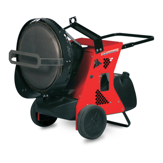
Summary of Contents for BIEMMEDUE FIRE 155
- Page 1 INFRARED RAY HEAT GENERATOR GÉNÉRATEUR DE CHALEUR À RAYONS INFRAROUGES V 120-60 Ed. 01/11 F F I I R R E E 1 1 5 5 5 5 F F I I R R E E 1 1 5 5 5 5 INSTRUCTIONS MANUAL LIVRET D’ENTRETIEN...
- Page 2 DIAGRAMM EINSTELLUNG DER ELEKTRODEN REGLAGE DES ELECTRODES 2-3 mm 3 mm...
- Page 3 OPERATING DIAGRAM SCHÉ MA DE FONCTIONNEMENT COMBUSTION CHAMBER 12 FUEL TANK CHAMBRE DE COMBUSTION RESERVOIR COMBUSTIBLE BURNER 13 RESET BUTTON WITH CONTROL LAMP BRULEUR BOUTON REARMEMENT AVEC LAMPE TEMOIN NOZZLE 14 MAIN SWITCH GICLEUR INTERRUPTEUR MARCHE-ARRET SOLENOID VALVE 15 ROOM THERMOSTAT PLUG LECTROVANNE PRISE THERMOSTAT D’AMBIANCE DIESEL PUMP...
-
Page 4: General Recommendations
IMPORTANT Before using the heater, read and understand all instructions and follow them carefully. The manufacturer is not responsible for damages to goods or persons due to improper use of units. GENERAL RECOMMENDATIONS The hot generator must be placed on a flat, stable and level sur- face to avoid machine tipping and/or gas oil leakage from the tank fuel The generator described in this manual is a portable oil-fuelled in- cap. -
Page 5: Stopping The Heater
STOPPING THE HEATER Set main switch (14) on “0” position or turn thermostat or other control device on lowest setting. The flame goes out and the fan continues to work for approx. 90 sec. cooling the combustion chamber. TRANSPORT Warning Before making any attempt to restart heater find and eliminate reason of overheating. - Page 6 OBSERVED FAULTS, CAUSES AND REMEDIES OBSERVED FAULT CAUSE REMEDY • Check mains • Check proper positioning and functioning of • No electrical current • switch • Check fuse • Check correct setting of heater control. • Wrong setting of room thermostat or other •...
-
Page 7: Recommandations Generales
IMPORTANT Avant d’utiliser le générateur, nous vous prions de lire attentivement toutes les instructions pour l’emploi, mentionnées ci-après, et d’en suivre scrupuleusement les indications. Le constructeur n’est pas responsable pour les dommages aux choses et/ou per- sonnes dus à une utilisation impropre de l’appareil. RECOMMANDATIONS GENERALES l’air, arrêt du ventilateur). -
Page 8: Transport Et Deplacement
position correspondant au premier stade (I S) ou au second stade (II • Contrôler l’état des câbles et des connexions haute tension sur S) : les quantités de chaleur irradiées à chacun des stades sont indi- les électrodes; quées dans le tableau technique Tab. I. •... - Page 9 ANOMALIES DE FONCTIONNEMENT, CAUSES ET SOLUTIONS ANOMALIE DE FONCTIONNEMENT CAUSE SOLUTION • Vérifier les caractéristiques de l’installation électrique • • Vérifier le fonctionnement et la position de • Le courant électrique n’arrive pas • l’interrupteur • Vérifier l’efficacité du fusible •...
- Page 10 WIRING DIAGRAM SCHEMA ELECTRIQUE FIRE 155 CONTROL BOX CONDENSER COFFRET DE SECURITE CONDENSATEUR ROOM THERMOSTAT PLUG FAN MOTOR PRISE THERMOSTAT D’AMBIACE MOTEUR DU VENTILATOR ELECTRIC PILOT LAMP FUA FUSE LAMPE TEMOIN D’ALIMENTATION FUSIBLE OVERHEAT THERMOSTAT ANTI-JAMMING FILTER THERMOSTAT DE SURCHAUFFE...
- Page 11 WIRING DIAGRAM SCHEMA ELECTRIQUE FIRE 155 TWO STAGE CONTROL BOX CONDENSER COFFRET DE SECURITE CONDENSATEUR ROOM THERMOSTAT PLUG FUA FUSE PRISE THERMOSTAT D’AMBIACE FUSIBLE ELECTRIC PILOT LAMP SOLENOID VALVE II° Stage LAMPE TEMOIN D’ALIMENTATION ELECTROVANNE II° Stade FUSE ANTI-JAMMING FILTER...
- Page 12 TECHNICAL SPECIFICATIONS FIRE 155 FIRE 155 TWO STAGE CARACTERISTIQUES TECHNIQUES - - - 120.96 Max heating output [kBTU/h] Puissance thermique max II S 154.24 146.52 - - - 0,92 Fuel consumption [USgal/h] Consommation II S 1,11 1,11 Fase - Phase Phase - Phase Fase - Фазы...


Need help?
Do you have a question about the FIRE 155 and is the answer not in the manual?
Questions and answers