
Related Manuals for SNDWAY SW-6510S


Summary of Contents for SNDWAY SW-6510S
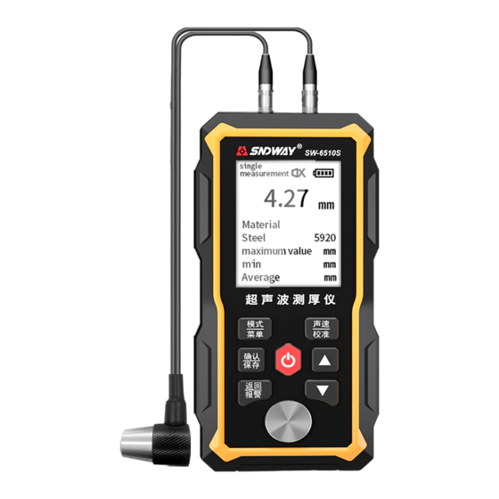
- Page 1 SW-6510S Scan 4.27 Mat: 5920 Steel ULTRASONIC THICKNESS GAUGE ULTRASONIC THICKNESS GAUGE...
-
Page 2: User Instruction
User Instruction Please read this instruction intently before your first utilization. 1. The instrument is not allowed to disassemble or repair in any ways.It is forbidden to do any illegal modification or perfor- mance change for laser emitter. Please keep it out of reach of children and avoid being used by any irrelevant personnel. -
Page 3: Packing List
1 Packing List Names Quantity Remark Standard Configuration User Manual The Meter Standard Probe(5mhz Ф10) Coupling Agent Portable Package USB Cable 2 Overview This instrument is an intelligent ultrasonic thickness gauge. It adopts the latest high-performance, low-power microprocessor technology. Based on the principle of ultrasonic measurement, it can measure the thickness of metals and other materials, and can measure the sound speed of materials. -
Page 4: Working Principle
2.1 Working principle The thickness measurement of this ultrasonic thickness gauge is that the ultrasonic pulse generated by the probe passes through the couplant to reach the measured object, part of the ultrasonic signal is reflected by the bottom surface of the object, and the probe receives the echo reflected by the bottom surface of the measured object, and accurately calculates the ultrasonic wave round-trip time, and calculate the thickness value... -
Page 5: Technical Parameter
2.3 Technical Parameter ITEMS SW-6510S Display 2.4 inch black and white dot matrix screen Language Chinese / English Measuring Range 1.00~300.00mm(the steel) Sound Velocity (1000~9999) m/s Unit 0.1mm / 0.01mm / 0.01in H<10mm, ±0.1mm; H≥10mm, ±(1%H+0.1)mm Accuracy H is the thickness of the object Lower limit of pipe Ф20*3mm(steel) -
Page 6: Structure And Appearance
3 Structure and appearance Scan 20.00 Mat: 5920 Steel 1. Housing 2. Buttons 3. Display 4. Transmitter socket 5. Receiver socket 6. Thickness calibration block 7. Nameplate 8. Ultrasonic thickness probe (probe for short) - 04 -... -
Page 7: Main Display Interface
3.1 Main Display Interface After the instrument is turned on, it will automatically enter the main display interface, as shown in the following figure: Scan 4.42 Mat: 5920 Custom 1 4.50mm 4.42mm 4.43mm 1) Coupling state: the coupling state between the probe and the workpiece to be measured 2) Measurement mode: display the current measurement mode 3) Unit system: mm (in metric system), or in (in imperial system) -
Page 8: Preparation Before Measurement
Note: When not in use for a long time, fully charge the product first, and recharge it every six months to avoid battery damage. 5 The general measurement process of the instrument A. Prepare the tested workpiece, refer to "6.1 Surface Treatment of Measured Workpiece". -
Page 9: Instrument Use
7 Instrument use 7.1 Turning the instrument on and off Power on: Insert the probe into the instrument, short press the to power on. Power off: long press the key to power off. Automatic shutdown: the instrument will automatically shut down if there is no operation, and the default time is 5 minutes. -
Page 10: Continuous Measurement
Figure 2. Smear the couplant evenly, and tightly couple the probe to the surface of the material to be tested. 7.3 Continuous measurement Apply the couplant evenly to the measured area, then couple the probe to the workpiece and move it along the surface of the workpiece. -
Page 11: Instrument Calibration
"Beep beep beep" alarm sound, at this time, the thickness of the object is detected to be unqualified. After the alarm, the user can press any key to exit the alarm, or continue to measure. 7.5 Instrument calibration Note: Probe calibration should be performed every time the probe is replaced, the ambient temperature changes greatly, or the measurement deviates. - Page 12 7.6 Measure sound speed in reverse Different materials have different speed of sound, the materials listed in "Appendix A" material and speed of sound are for reference only. The function is used to determine the sound velocity of the workpiece material. The steps to measure the speed of sound are as follows: 1) Calibrate the instrument first.
- Page 13 7.7 Selection of sound speed The user can select the speed of sound according to the material. When the current unit is mm, the unit of sound speed is m/s, and when the unit is in, the unit of sound speed is in/us. In the display state of the main interface, short press to enter the material selection.
-
Page 14: Storage Function
7.8 CLEAR MEASUREMENT RESULT In single measurement and continuous measurement, short press to clear the current measurement result (including maximum value, minimum value and average value). Continuous measurements do not clear the measurement until the probe is removed. 7.9 Storage function In single measurement and continuous measurement, long press to save records, each record includes current... -
Page 15: Material Selection
7.10 MENU The menu includes: material selection, sound speed adjustment, unit, recording operation, system setting, about, and factory reset. Long press to enter the menu, the operation is as follows: Menu Select the previous option Material Select the next option Speed Enter the selected option Unit... -
Page 16: The Adjustment Of Sound Velocity
7.12 THE ADJUSTMENT OF SOUND VELOCITY Select Speed in the menu to adjust the range of sound speed settings: The default value is ±200m/s (0.008in/us), and the adjustable range of custom materials is: 1000m/s to 9999m/s (0.039in/us to 0.394in/us). Increase the value of sound velocity, long press to speed up adjustment Decrease the value of sound... - Page 17 7.14 RECORD Select Records in the menu. When the instrument has no record, it will prompt "no stored value" and cannot enter the record operation. Records Up to choose functions first page Down to choose functions last page Enter the selected functions selected item Return to the menu Delete the item...
- Page 18 View record details: Enter the selected page, press to select the record number, and press to view the details (details include record number, current value, maximum value, minimum value, and current value). After viewing details, short press to return to the record list. Data 4.50 Mat:...
- Page 19 Adjust the record number Select group Confirm the number of digits currently modified (hundreds/tens/ Select group From 001 to 009 units of record number), When the units digit is confirmed, enter the selected record number Return to the record operation interface 7.14.4 Deleted selected groups In the record operation interface, select the "Delete Selected...
-
Page 20: Delete All Records
7.14.5 Delete all records Select the "Delete All" function in the record operation interface, the user can choose to delete all records. Use to select "Yes/No", select Yes, press to delete all records; select No, press to return to the record operation interface. Press to directly return to the record operation interface. -
Page 21: Sound Settings
7.16 Sound Settings In the system settings interface, select the Sound function, the sound settings interface. Sound Select sound on/off Save and return to menu Return to system settings 7.17 Backlight time Select the "Backlight Setting" function in the system setting interface to adjust the backlight time. -
Page 22: Alarm Settings
7.19 Alarm settings Select the Alarm function in the system setting interface to adjust the standard value first. And press to adjust the tolerance limit. Long press to increase the adjustment range Increase standard value / Alarm increase tolerance limit Reduce standard value / 4.00 Standard... -
Page 23: About The Device
7.21 About the device About Select in the settings menu and press to return to the menu. The content will be updated in the future, please take the actual situation as the standard and will not be updated here. About ID:UTG China Version:V.202101 7.22 Reset... -
Page 24: Maintenance And Precautions
object. In the secondary measurement, the dividing plane of the probe is 90°, and the smaller value is the thickness value. ● Multi-point measurement method: make multiple measurements in a circle with a diameter of about 30mm, and take the minimum value as the thickness value. ●... - Page 25 9.2 Precautions during measurement ● When measuring, it is a good measurement only when the coupling icon appears and is stable; ● If there is a lot of couplant on the surface of the object to be measured, when the probe leaves the surface of the object to be measured, the couplant will cause error.
-
Page 26: Clean The Case
9.4 Clean the case Alcohol, diluent, etc. have a corrosive effect on the case, especially the window, so when cleaning, just wipe it gently with a damp cloth. 9.5 Maintenance When the instrument has abnormal phenomena (such as the instrument is damaged and cannot be measured; the liquid crystal display is abnormal;... -
Page 27: Appendix A Materials Sound Velocity
Appendix A Materials sound velocity Attention:All of sound velocity is approximate value, just for reference. sound velocity material in/µs custom 1 User define 1 0.233 5920 User define 2 custom 2 0.233 5920 custom 3 User define 3 0.233 5920 Aluminum Aluminum 0.250... -
Page 28: Appendix B Common Problems And Solutions In Ultrasonic Thickness Measurement
Appendix B Common Problems and Solutions in Ultrasonic Thickness Measurement B.1 Influence of Surface Condition on Measurement Results B.1.1 Surface covering Before measurement, all dust, dirt and rust on the surface of the object to be measured should be removed, and paint and other coverings should be removed. - Page 29 tested, the reading on the screen will change regularly, Select the lowest value of the readings as the measured thickness of the material. According to the curvature of the material, select the correct direction of the angle between the probe crosstalk barrier plate and the axis of the material to be tested.
- Page 30 B.3 Influence of material attenuation on measurement results For some materials such as fibers, porous, coarse crystals, etc., they will cause a lot of scattering and energy attenuation of ultrasonic waves, so that the instrument may have abnormal readings or even no readings (usually abnormal readings are smaller than the actual thickness).
- Page 31 The internal structure of most forgings and castings is directional. In different directions, there will be a small change in the speed of sound. To solve this problem, the test block should have an internal structure in the same direction as the material to be tested, and the sound waves in the test block.
- Page 32 echo will be generated, which will cause an incorrect reading in the thickness measurement result and cause a misjudgment. In addition, with the coarsening of the grains, the anisotropy in the crystallographic direction of the metal becomes more pronounced, resulting in differences in the speed of sound in different directions, and the maximum difference can even reach 5.5%.
- Page 33 B.6.2 Rust spots, corrosion pits, etc. Rust spots and pits on the other surface of the tested material (small rust spots are sometimes difficult to find), etc., will cause irregular changes in readings, and even no readings in extreme cases. When a pit is found or suspect, the measurement of this area must be very careful, and the probe crosstalk barrier can be positioned at different angles to make multiple tests.
- Page 34 B.6.6 Influence of oxide layer on metal surface Some metals may have a denser oxide layer on their surface, such as aluminum, etc. This layer of oxide layer is closely combined with the substrate, and there is no obvious interface, but the propagation speed of ultrasonic waves in these two substances is different, so it will cause measurement error, and the size of the error is also different for the thickness of the...
- Page 36 Dongguan Sndway Electronic Co.,Ltd. Add: Sndway Science & Technology Industrial Park, 58 Tuanjie Road, Humen 523930, Dongguan, China Services Hotline: 400-125-6969 Tel: 0769-85265688 Fax: 0769-85116652 Url: www.sndway.com...
Need help?
Do you have a question about the SW-6510S and is the answer not in the manual?
Questions and answers
Can I use to measure wall thickness (300 mm)?
Yes, the SNDWAY SW-6510S can measure wall thickness up to 300 mm in steel.
This answer is automatically generated