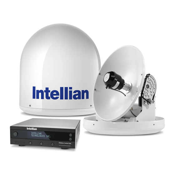
Intellian i2 Installation Manual
Hide thumbs
Also See for i2:
- Installation and operation manual (64 pages) ,
- Operation manual (75 pages)
Table of Contents
Advertisement
Quick Links
Installation
The components of the Intellian i2 have been designed to be modular so
that it is suitable for simple installation on all types of vessels.
System Components
Antenna Unit
The antenna of Intellian i2 is comprised with the following components
for optimum search and reception of the satellite signal.
• Mechanical Unit – manipulates the antenna to receive an optimal
satellite signal regardless of the movement of the vessel.
• Control Unit – controls mechanical operation of the antenna.
• RF Unit – transmits an optimum satellite signal to the receiver.
• Radome – protects the antenna from severe marine environmenta
Figure 02 : Radome
7
Advertisement
Table of Contents

Summary of Contents for Intellian i2
- Page 1 Installation The components of the Intellian i2 have been designed to be modular so that it is suitable for simple installation on all types of vessels. System Components Antenna Unit The antenna of Intellian i2 is comprised with the following components for optimum search and reception of the satellite signal.
- Page 2 Intellian Satellite TV Antenna Systems Antenna Control Unit (ACU) Front The Antenna Control Unit (ACU) provides the power to the antenna and controls various settings of the antenna. The digital VFD (Vacuum Fluorescent Display) allows for easy operation of the ACU, even in the dark.
-
Page 3: Installation Kit
Installation Kit Other Components Contains the items required for securing the antenna unit and ACU to the vessel. Components Size ACU Bracket Antenna RG6(Antenna – ACU RF Cable) RG6(ACU – IRD Cable) Power Cable Item PC Serial Cable 1.8m Spring Washer Hex.Bolt Flat Washer Hex. -
Page 4: Tools Required For Installation
Intellian Satellite TV Antenna Systems Tools Required for Installation Power Drill Power Drill 11 mm Spanner 11 mm Spanner 8 mm Drill Bit 8 mm Drill Bit Pencil Pencil Cross-Head Cross-Head Ø50 mm Ø50 mm Screwdriver Screwdriver 10 mm Spanner... -
Page 5: Planning The Installation
Planning the Installation Selection of Installation Site Install the antenna in accordance with the following procedures to ensure maximum performance of the antenna. The antenna should be installed in a place where it has an all-round clear view of the horizon. Please be sure there are no obstacles within 15°... -
Page 6: Power Requirements
RF cable supplied by system. Intellian Technologies. • Intellian i2 has been designed to work on a boat’s power supply rated at 12V / 24V DC (acceptable range: 9~30 V DC). • If your IRD(s) and television(s) require a 110V/240V AC power supply,... - Page 7 Before installing the antenna, open the radome and remove the Note: shipping constraints from the antenna interior. Reinstall the radome before operating the system. The system will not perform properly if the Ø37 cm (14.7”) radome is open. Figure 08 : Radome Dimension of i2...
- Page 8 RF connector from being exposed to sea water and external shocks. An power tower by drawing a square of 14.4cm (5.7”) exposed cable may cause electric shock and cause serious damage to the equipment. 14.4cm (5.7”) Figure 09 : Intellian i2...
- Page 9 Securing Holes for Bolts and Cable Ways Connection of the Cable Make 4 bolt holes of 8mm diameter, one at each corner of a rectangle Remove the rubber cap from RF connector. Connect the RF cable to the drawn as below, and make a circular hole of 50mm diameter at the RF connector under the base plate through the access hole using an center of the rectangle through which the cable will run.
-
Page 10: Mounting The Antenna
Intellian Satellite TV Antenna Systems Installing the ACU ACU Dimensions Mounting the Antenna Fix the antenna to the holes made before as shown in the drawing below by using the hex head bolts (M6 X 35L), M6 spring washer, 22.8cm(9”) M6 flat washer and M6 Nut supplied.


Need help?
Do you have a question about the i2 and is the answer not in the manual?
Questions and answers