
Related Manuals for Intellian t80Q


Summary of Contents for Intellian t80Q
- Page 1 / t80Q Installation and Operation User Guide Marine Satellite Television Antenna System...
-
Page 2: General Precautions
To avoid damage to radome paint, do not use a cover on the radome. Using any type of cover may cause paint damage. Intellian radomes are designed to withstand exposure to rain, humidity, and sun/UV rays when assembled according to Intellian instructions, and when the supplied approved hardware and sealants are used. - Page 3 Information in this document is subject to change without notice. Every effort has been made to ensure that the information in this manual is accurate. Intellian is not responsible for printing or clerical errors.
- Page 4 INDEX...
- Page 5 INDEX INTRODUCTION Intellian t80W/t80Q Introduction Intellian t80W/t80Q Features INSTALLING THE ANTENNA System Package Planning the Installation Antenna Installation INSTALLING THE ACU Mounting the ACU Connecting the System Cables PC to ACU Commnunication Setup Wi-Fi Connection OPERATING THE ACU Introduction Normal mode...
- Page 6 CE & FCC Declaration of Conformity (DoC) We, Intellian Technologies, Inc. located at 2F Dongik Bldg., 98 Nonhyun-dong, Kangnam-gu, Seoul 135-080, Korea declare under our sole responsibility that the product(s) described in the below to which this declaration relates is in conformity with the requirements of the EU EMC Directive 89/336/EEC and FCC 47 CFR Part 15 Subpart B when the methods, as described in EN 60945: 2002, ANSI 63.4: 2003 and EN 60950-1:2006+A11:2009+A1:2010+A12:2011,...
- Page 8 – Marine Satellite TV Antenna System...
- Page 9 INTRODUCTION INTRODUCTION Intellian t80W/t80Q Introduction Intellian t80W/t80Q Features...
- Page 10 TV convenience, as well as unparalleled access to the greatest number of channels at sea. The Intellian t80W is the TV antenna capable of operating in all global market without the need of changing the LNB unit inside of antenna's dome.
- Page 11 Some of the HD TV services have moved to DVB-S2 transmission formats and there will be more in the future. Thanks to Intellian's groundbreaking DVB-S2 digital TV technology, now boaters are able to enjoy their favorite Sat TV entertainment at sea, just like home.
- Page 12 ACU and monitor, control and change the settings of the system wirelessly. An Intellian App is available for download to access to the ACU via Wi-Fi and operate the antenna from iPhone, iPad or other network devices.
-
Page 13: Installing The Antenna
INTRODUCTION INSTALLING THE ANTENNA System Package Antenna Unit ACU (Antenna Control Unit) Installation Kit Planning the Installation Selection of Antenna Installation Site System Cables RF Cable (Customer supplied) Power Requirement Gyrocompass / GPS Interface Cable (Customer supplied) Tools required for Installation Antenna Installation Unpacking the Package Box Antenna Dimensions... -
Page 14: System Package
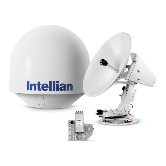
– Marine Satellite TV Antenna System System Package The Intellian t80W/t80Q consists of two major units, an antenna unit and the antenna control unit (ACU). Antenna Unit The antenna unit includes an antenna pedestal inside a radome assembly unit. The... -
Page 15: Installation Kit
INSTALLING THE ANTENNA ACU (Antenna Control Unit) Antenna Control Unit (ACU) provides the power to the antenna and controls the various settings of the antenna. Additionally, VFD (Vacuum Fluorescent Display) allows you to operate the ACU in the dark. Front panel Rear panel Installation Kit Contains the items required for mounting the antenna unit and ACU to the vessel. -
Page 16: Other Components
– Marine Satellite TV Antenna System Q’ty Description Size Remark Self-Tapping Table Mount ø 4 x 16 Screw Bracket Rack Mount Flat Head Screw M4 x 12L Bracket ACU Table Mount Sems Bolt M3 x 12L Bracket ACU Other Components Image Q’ty... - Page 17 INSTALLING THE ANTENNA Image Q’ty Description Size Remark Rubber Gland RG6 Cable-Antenna Hex Socket M6 x 40L Radome (Top-Bottom) Head Cap Spring Washer Radome (Top-Bottom) Flat Washer Radome (Top-Bottom) Wi-Fi Antenna 110mm USB Flash Drive Mounting Template Quick Installation Guide...
-
Page 18: Planning The Installation
– Marine Satellite TV Antenna System Planning the Installation Selection of Antenna Installation Site Install the antenna in accordance with the following procedures to insure maximum performance of the antenna. The antenna should be installed in a place where there is all round clear view of the horizon. -
Page 19: Power Requirement
RF Cable (Customer supplied) Due to the signal losses across the length of the RF coax on L-Band, Intellian recommends the following 75 ohm coax cable types for standard system installations. For cables that run longer than 100 meters, please consult Intellian Technologies. -
Page 20: Pin Signal
– Marine Satellite TV Antenna System • NMEA 0183 Connector Signal NMEA 0183 - NMEA 0183 + • GPS Connector ACU GPS In/Out Port D-Sub 9 pin Female Signal GPS OUT + GPS IN + • NMEA 2000 Connector... -
Page 21: Tools Required For Installation
INSTALLING THE ANTENNA Tools required for Installation 11 mm Spanner 5 mm Allen/Hex key 13 mm Spanner Cross Head Screwdriver 19 mm Spanner Flat Head Screwdriver... -
Page 22: Antenna Installation
– Marine Satellite TV Antenna System Antenna Installation Unpacking the Package Box Step 1. Remove the top panel. Step 2. Remove ACU box and installation kit box. - Page 23 INSTALLING THE ANTENNA Step 3. Remove the 4 shipping bolts that mount the antenna to the pallet. WARNING: When lifting the antenna by using the lifting strap, ensure to disassemble the antenna and the pallet.
- Page 24 – Marine Satellite TV Antenna System Step 4. Open the top radome and remove the red shipping restraints (3 fixing brackets mounted to the antenna pedestal and the azimuth axis). M6 Flat Washer M6 Spring Washer M6 Hex Wrench Bolt...
-
Page 25: Antenna Dimensions
INSTALLING THE ANTENNA Antenna Dimensions The method of installation and mounting of antenna may vary with vessel design but the following procedures are applicable in most situations, and will result in a secure and effective installation. Confirm the height and diameter of the antenna before installing it. - Page 26 – Marine Satellite TV Antenna System Antenna Mounting Hole Pattern Use the supplied mounting template when drilling mounting holes on the mast. The hole placement for the antenna must match the mounting hole pattern on the template. WARNING: When reusing an existing mast, check the condition of holes on the mast and make sure those are proper to use compared to the hole locations and sizes printed on the mounting template.
- Page 27 INSTALLING THE ANTENNA Antenna Mounting Hole Template NOTE: This is a real-size template. Make sure the hole placement for the antenna is the same with the template even though the mast has a different shape, and mount the antenna on a flat surface of the mast. 247.5 mm (9.74”) Drill hole Ф15 mm (0.59”)
- Page 28 RF cables to the cable connectors on the inside of the radome. Mounting the Radome Bolt the radome base directly to the support pedestal. Makesure to use the Intellian supplied blots from the accessory box when you mount the radome. Antenna Unit M12 x 80L Hex.
- Page 29 INSTALLING THE ANTENNA RF Cable Connections Before installing the RF cable, ensure that the RF cable labeled with RF1 is prop- erly connected between the antenna control unit and the power switch box. Connect the 4 RF cables to the RF connectors using an 11mm spanner. Ensure that the power switch is off during the installation period.
- Page 30 – Marine Satellite TV Antenna System Cable connection of Power Switch Box NOTE: There are 4 RF connectors on the power box. Be sure to connect each cable to its corresponding RF connectors.
- Page 31 M6 Spring Washer M6 Hex Wrench Bolt Note: Make sure to use the Intellian supplied bolts from the accessory box when you reinstall the top radome. Apply Loctite #262 or equivalent to the bolt thread, and fasten it to a torque setting of 3.5Nm.
- Page 32 – Marine Satellite TV Antenna System Position the Radome Position the antenna with the BOW direction parallel to the center line of the ship. Recommended size of the support pedestal Base Panel Min 0.8cm(0.3”) Max 1.2cm(0.5”) Base Panel Min 60cm(24”) Supporting Pole Max 150cm(60”)
-
Page 33: Installing The Acu
INSTALLING THE ACU Mounting the ACU 19” Rack Mount Type Table Mount Type ACU Dimensions Selection of ACU Installation Site Connecting the System Cables Multi-Switch Connection Receivers Direct Connection Gyrocompass Connection Connecting the System without a Ship’s Gyrocompass PC to ACU Commnunication Setup TCP/IP Connection Serial/USB Connection Wi-Fi Connection... - Page 34 – Marine Satellite TV Antenna System Mounting ACU Intellian supplies two types of mounting methods 19” Rack Mount Type and Table Mount Type to mount your ACU. Figure 01. 19" Rack Mount Type 19” Rack Mount Type - The ACU should be installed using the two supplied Rack Mounting Brackets which allow for a side 19”...
-
Page 35: Acu Dimensions
INSTALLING THE ACU ACU Dimensions 47.5 cm (18.7") 45.5 cm (17.9") 43.1 cm (17") 4.4 cm (1.7") 46.6 cm (18.4") 48.5 cm (19.1") Figure 03. Dimension of ACU Selection of ACU Installation Site • The ACU should be installed below deck, in a location that is: •... -
Page 36: Connecting The System Cables
Intellian WorldView LNB module. The t80Q is optimized for European waters using by Universal Quad LNB has two LO(9.75GHz, 10.6GHz) and the Universal Quad LNB module. It provides higher optimized gain for especially European water. - Page 37 INSTALLING THE ACU Receiver 1 RF 1 (VL) RF 2 (HL) Receiver 8 RF 3 (VH) Multi Switch RF 4 (HH) Figure 04. Multi-Switch Connection Configuration • Connect the RF cable from the ACU's RF1 connector on the power switch box located inside of the radome to the ANT.
- Page 38 – Marine Satellite TV Antenna System Receivers Direct Connection In Universal LNB mode, RF1, RF2, RF3 and RF4 can be connected, however, when you switch and use the system from universal LNB mode (ex. Europe) to single LNB mode (ex. US), RF3 and RF4 will not work and only RF1 and RF2 will transfer the satellite's signal.
-
Page 39: Recommended Cable
INSTALLING THE ACU Gyrocompass Connection For optimum satellite tracking, you must connect a Gyrocompass to the antenna system through the gyrocompass interface on the rear of the ACU. If the ship’s gy- rocompass output is other than NMEA 0183 and NMEA 2000 a separate purchase of an NMEA converter is required. - Page 40 Connecting the System without a Ship’s Gyrocompass For a vessel where the ship’s gyrocompass is not installed or is difficult to be connected, the Intellian Gyro-Free satellite search function will be automatically enabled to allow the antenna to lock onto the desired satellite without requiring an external heading input.
-
Page 41: Pc To Acu Communication Setup
1. Connect an Ethernet cable from a PC Ethernet port to the Management port Ethernet Port on the front of the ACU. 2. Network connection is established. 3. Use the following IP address to access Intellian Aptus or Aptus Web page. ® • 192.168.2.1 (Default) Connection through Rear Panel Ethernet Port This method requires separate IP configuration on a PC. -
Page 42: Serial/Usb Connection
1. Connect a USB cable from a USB port on your PC to the USB port on the ACU. Note: The t80W/t80Q also supports Wi-Fi connection between a PC and the ACU. - Page 43 INSTALLING THE ACU Wi-Fi Connection Setup Wi-Fi Connection • Setting up the ACU in order to access Wi-Fi • Setting up the PC (AP Mode) in order to access Wi-Fi • Remote Aptus Web Confirmation Setting up the ACU in order to access Wi-Fi 1.
- Page 44 – Marine Satellite TV Antenna System Setting up the PC in order to access Wi-Fi 1. Setting up my computer’s wireless IP address - Control Panel> Network and Sharing Center > Change Adapter Settings > Right click on the “Bluetooth Wireless Connection”> Click Properties After selecting TCP/IPv4, click on the properties menu, then select "Obtain an IP...
- Page 45 INSTALLING THE ACU 3. Connect Wi-Fi in AP mode. After clicking on the Windows Wireless Connection icon, click on intellian-TVRO (Default). 4. Enter the Network Security Key. Key: intellian1234 (Default) 5. You can confirm the logo and version data by accessing http://192.168.1.223 Aptus Web v X.XX...
- Page 46 – Marine Satellite TV Antenna System...
-
Page 47: Operating The Acu
OPERATING THE ACU OPERATING THE ACU Introduction Normal Mode Startup Change of Target Satellite Monitoring Current Status Setup Mode Setting the Region Installation Settings Installation Antenna Settings Setting Antenna Manual Search Setting POL. Angle Setting Antenna Search Parameter Setting Antenna Parameters Executing Antenna Diagnosis Satellite Settings Setting the Satellite Pair... - Page 48 Please ensure that your Intellian system is ALWAYS powered ON upon leaving the dock. Failure to follow these instructions could result in damaging mechanical parts in the antenna and/or possibly void your warranty. Intellian strongly recommends to restrain the antenna pedestal properly while underway when power is removed from...
-
Page 49: Normal Mode
OPERATING THE ACU Normal Mode Startup With the system installed and power applied, the ACU screen will show the following sequence. I N T E L L I A N T E C H N O L O G I E S I N C . I N T E L L I A N t 8 0 W 1. - Page 50 [ 1 ] A S T R A _ 1 [ 2 ] H O T _ S P O T 4. The antenna is tracking satellite [3]. NOTE: If you have any problems while setting target satellites, contact the Intellian service team for support.
- Page 51 OPERATING THE ACU Monitoring Current Status While POWER ON the Intellian ACU displays the status of the antenna. Various ACU displays may be shown according to the current status of the antenna. [ 4 ] A S T R A _ 1...
- Page 52 – Marine Satellite TV Antenna System D V B _ D F : 1 1 5 0 9 S : 2 2 0 0 0 X 0 0 0 1 A G C : 3 0 1 4 . 5 3 E 5 2 .
-
Page 53: Setup Mode
OPERATING THE ACU Setup Mode To enter Setup Mode simply follow the instructions below: • T R A C K I N G 1 9 . 2 E A S T R _ 1 A G C : 3 0 1 A Z : 1 6 0 . - Page 54 – Marine Satellite TV Antenna System Setting the Region S E T U P M O D E ? 4 Y E S 1. Press the LEFT arrow key to move cursor to YES and press the OK key to enter SETUP mode.
- Page 55 [ 3 ] A S T R A _ 3 9. Region information has been updated. NOTE: If you have any problems while performing these steps, contact the Intellian service team for support. And refer to the "Appendix: Library Upgrade Guide" page for more details.
-
Page 56: Installation Settings
– Marine Satellite TV Antenna System Installation Settings Installation S E T U P M O D E ? Y E S 1. Press the LEFT arrow key to move cursor to YES and press the OK key to enter setup mode. - Page 57 OPERATING THE ACU L A T I T U D E L O N G I T U D E 5 2 . 2 2 N 4 . 5 3 E 6. Set the current LATITUDE . Press the LEFT and RIGHT arrow keys until the desired character is underscored (selected).
- Page 58 – Marine Satellite TV Antenna System L O A D I N G . . . D O N O T T U R N O F F ! 10. Setting is being loaded to the system. The ACU will restart the system automatically after uploading the setting.
-
Page 59: Antenna Settings
OPERATING THE ACU Antenna Settings Setting Antenna Manual Search S E T U P M O D E ? 4 Y E S 1. Press the LEFT arrow key to move cursor to YES and press the OK key to enter SETUP mode. - Page 60 – Marine Satellite TV Antenna System Setting POL. Angle S E T U P M O D E ? 4 Y E S 1. Press the LEFT key to move cursor to YES and press the OK key to enter setup mode.
- Page 61 OPERATING THE ACU Setting Antenna Search Parameter S E T U P M O D E ? 4 Y E S 1.Press LEFT arrow key to move cursor to YES and press OK key to enter SETUP mode. 4 + A N T E N N A + S A T E L L I T E + S Y S T E M + I N S T A L L A T I O N...
- Page 62 – Marine Satellite TV Antenna System A search pattern 1 or 3 will be initiated according to which GYRO TYPE is selected and the existence of the gyro input. Search 1: a search pattern 1 will automatically be initiated when the ship’s heading input does not exist / is failed .The antenna will go to the relative azimuth...
- Page 63 OPERATING THE ACU Search 3: a search pattern 3 will automatically be initiated when AGC falls below the current tracking level threshold value. If the desired signal is found and above the predefined tracking level, the ACU will terminate Search 3 and go into TRACKING mode. A search pattern will automatically be initiated when AGC falls below the current threshold setting (indicates that satellite signal has been lost).
-
Page 64: Setting Antenna Parameters
– Marine Satellite TV Antenna System Setting Antenna Parameters S E T U P M O D E ? 4 Y E S 1. Press the LEFT key to move cursor to YES and press the OK key to enter setup mode. - Page 65 OPERATING THE ACU Peak Level Tracking Level Detect Level Noise Level D E T E C T L E V E L T R A C K I N G L E V E L 0 6 0 0 3 0 6.
- Page 66 – Marine Satellite TV Antenna System V O L T T H R E S . S C A N O F F S E T 0 6 5 0 9. Set the VOLT THRES. The voltage threshold is to distinguish the voltage between 13 V and 18V.
- Page 67 OPERATING THE ACU U S E O F F S E T O F F S E T D I F F . Y E S - 0 4 0 13. Set the USE OFFSET. USE OFFSET is to determine whether the system uses OFFSET DIFF or not. USE OFFSET and OFFSET DIFF are pair functions.
- Page 68 – Marine Satellite TV Antenna System Executing Antenna Diagnosis S E T U P M O D E ? 4 Y E S 1. Press the LEFT key to move cursor to YES and press the OK key to enter setup mode.
- Page 69 OPERATING THE ACU Diagnosis Code : CODE 101 : The data communication between the antenna and the ACU is tested. CODE 102 : The azimuth motor is tested. CODE 103 : The elevation motor is tested. CODE 104 : The cross-level motor is tested. CODE 105 : The azimuth encoder is tested.
-
Page 70: Satellite Settings
– Marine Satellite TV Antenna System Satellite Settings Setting the Satellite Pair S E T U P M O D E ? 4 Y E S 1. Press the LEFT arrow key to move cursor to YES and press the OK key to enter setup mode. - Page 71 OPERATING THE ACU Edit Satellite Information S E T U P M O D E ? 4 Y E S 1. Press the LEFT arrow key to move cursor to YES and press the OK key to enter setup mode. 4 + S A T E L L I T E + A N T E N N A + S Y S T E M...
- Page 72 – Marine Satellite TV Antenna System L O N G I T U D E E D I T N A M E 1 9 . 2 0 E A S T R A _ 1 7. Set the SATELLITE NAME.
- Page 73 OPERATING THE ACU L O C A L F R E Q . 1 0 6 0 0 12. Set LOCAL FREQ. Press the UP and DOWN arrow keys to select the LNB local frequency from the installed LNB. Or press the NUMBER keys to set the desired value directly. Press the OK key to set the parameter.
- Page 74 – Marine Satellite TV Antenna System 1) Verification Method AGC – use signal level for satellite tracking. DVB LOCK – use DVB Lock for satellite tracking. DVB DECODE – use DVB Decode for satellite tracking. DSS DECODE – use DSS Decode for satellite tracking.
- Page 75 OPERATING THE ACU Finding Transponders S E T U P M O D E ? 4 Y E S 1. Press the LEFT arrow key to move cursor to YES and press the OK key to enter setup mode. 4 + S A T E L L I T E + A N T E N N A + S Y S T E M + I N S T A L L A T I O N...
- Page 76 – Marine Satellite TV Antenna System [ C H E C K N I D ] F : 1 1 5 0 9 S : 2 2 0 0 0 0 x 0 0 01 P R E S S O K R E C E I V E D N I D [ 0 x 0 0 0 1 ] 7.
-
Page 77: System Settings
OPERATING THE ACU System Settings Setting Location S E T U P M O D E ? 4 Y E S 1. Press the LEFT arrow key to move cursor to YES and press the OK key to enter setup mode. - Page 78 – Marine Satellite TV Antenna System GYRO TYPE* NO DEVICE NMEA NMEA2000 GROUND TEST 4 L A T I T U D E L O N G I T U D E 5 2 . 2 2 N 4 . 5 3 E 5.
-
Page 79: System Management
OPERATING THE ACU System Management S E T U P M O D E ? 4 Y E S 1. Press the LEFT arrow key to move cursor to YES and press the OK key to enter setup mode. + A N T E N N A + S A T E L L I T E 4 + S Y S T E M + I N S T A L L A T I O N... - Page 80 – Marine Satellite TV Antenna System SELECT PROCESS TYPE* BACKUP USER DATA: To backup the antenna settings set by user to the ACU. RESTORE USER DATA: To restore the antenna by using the backup user data stored from the ACU.
- Page 81 OPERATING THE ACU Key Lock S E T U P M O D E ? 4 Y E S 1. Press the LEFT arrow key to move cursor to YES and press the OK key to enter setup mode. + A N T E N N A + S A T E L L I T E 4 + S Y S T E M + I N S T A L L A T I O N...
- Page 82 – Marine Satellite TV Antenna System...
- Page 83 Aptus ® OPERATING THE ACU Introduction to Aptus ® Requirements Software Installation PC to ACU Communication Setup Starting Aptus ® Establishing a data communication AutoUpdate Toolbar Menus System Property Status Dashboard Work View Tabs 1. Antenna – Basic Info. 2. Antenna – Advanced Info. 3.
-
Page 84: Introduction To Aptus
– Marine Satellite TV Antenna System Introduction to Aptus ® Intellian’s Antenna PC Controller Software, Aptus is a next-generation graphically ® based antenna remote control software. The Aptus allows users to easily and ® conveniently set up the antenna by using a personal computer. -
Page 85: Software Installation
® computer/ laptop. The InstallShield Wizard will guide you through the program setup process. The installation routine provides an icon on the desktop. Click the icon to start the software. In addition, Intellian also provides patch files for software upgrade. - Page 86 – Marine Satellite TV Antenna System PC to ACU Communication Setup Starting Aptus ® Double-click the Aptus desktop icon, then Communication Window appears ® to establish the data communication between your PC and the ACU. Select options of connection method to access your ACU either through the Serial Port...
- Page 87 Doing so will disable current PC Software Control because the USB connection has higher priority than TCP/IP connection. - The amount of data will increase rapidly if Network Communication is in use. Intellian recommends using Aptus Web to access the ACU.
-
Page 88: Auto Update
– Marine Satellite TV Antenna System AutoUpdate ® Intellian Aptus checks and notifies the latest version when it is started to maintain up to date software version by AutoUpdate function. 1. When Aptus ® is started, it automatically checks the latest software version from the server and runs AutoUpdate if new version is available. -
Page 89: Toolbar Menus
Aptus ® Toolbar Menus The toolbar menus at the top of the screen display command buttons of the most commonly used functions of the Aptus . The toolbar menus consists of 6 main ® menus; Quick (for quick launch of functions), File (for file backup, restoring and loading), View(for user layout and work view), Connection(for communication), Utill(for firmware uploading and spectrum view) and Help(for reporting problems and information check) . - Page 90 – Marine Satellite TV Antenna System Load Config. : loads the antenna configuration file (file format: *.cfg). The configuration file includes the antenna control parameters which are pre-loaded at the factory and should only be changed by an authorized service technician.
- Page 91 • Spectrum: displays current spectrum graph and allows to set spectrum data view options. Help • Report: provides e-mail contact to Intellian technical support team to let the user report problems at any time. • Information: displays the information of current Aptus ®...
-
Page 92: System Property Status Dashboard
– Marine Satellite TV Antenna System System Property Status Dashboard The property status dashboard on the left pane of the screen provides the antenna status, signal level, GPS and heading status, software information, product information and error status to be monitored quickly. - Page 93 Aptus ® - Search 3: Search 3 pattern will automatically be initiated when AGC falls below the current tracking level threshold value. Once the desired signal is found and above the predefined tracking threshold, the ACU will enter to tracking mode. - Tracking: Antenna is tracking the target satellite.
-
Page 94: Work View Tabs
– Marine Satellite TV Antenna System Work View Tabs Aptus provides seven Work View Tabs (Satellite View, Antenna Basic View, ® Antenna Advanced View, Monitor View, Graph View, ACU System View, and Satellite View) to manage the Antenna and the Satellite configuration. - Page 95 Aptus ® - GPS: displays and sets current antenna’s GPS. - Heading: displays and sets current ship’s heading information. · Heading Device: None / NMEA/ NMEA 2000/Ground Test. The baud rate (4800/ 9600/ 19200/ 38400) must be set if NMEA is selected. - Bow Information: displays and sets current antenna’s bow.
- Page 96 – Marine Satellite TV Antenna System 2. Antenna – Advanced Info. This view provides information on the Tilt Sensor Bias, Rate Sensor, Conical Range, Parameter Setting, Threshold Setting, Search Parameter and Flag Setting. -Tilt Sensor Bias: This maintains the elevation and the cross level axes in order to keep the pedestal parallel to the horizon.
- Page 97 Aptus ® · Step 4. Press the “Restart” icon to restart the antenna. - Rate Sensor: is used to calibrate the DC voltage output from the three rate sen- sors (azimuth, elevation, and cross-level). These are used to sense antenna motion that corresponds to the ship’s motion (roll, pitch, and yaw) for stabilizing the ped- estal.
- Page 98 – Marine Satellite TV Antenna System - Threshold Setting: set the threshold level for detecting and tracking the satellite signal. · DVB Detect Level: displays and sets signal detection threshold level when DVB tracking mode is in use. · DVB Tracking Level: displays and sets signal tracking threshold level when DVB tracking mode is in use.
-
Page 99: Transponder Information
- LNB Local Frequency: Displays or sets LNB local frequency and its corre- sponding LNB voltage supplied. You may select pre-programmed LNB LO settings from the drop down list. This procedure is same for both the Intellian Global VSAT PLL LNB and any other LNB. - Page 100 – Marine Satellite TV Antenna System - Pol & Band Control: The “Pol” controls 13V (Vertical/RHCP band) or 18V (Horizontal/ LHCP band). The “Band” controls DiSEqC 0KHz tone (Low band) and 22KHz tone (High band). After modifying information, press ‘Edit Satellite Informa- tion’...
- Page 101 Aptus ® 4. Graph View This view provides information on Signal, Elevation (EL), Absolute AZ (Azimuth), Relative AZ, Heading, AZ and EL in Single or Multi graph formats. - Select Graph Item: shows the graphs of only the checked item(s) in a Single or Multi Graph View.
- Page 102 – Marine Satellite TV Antenna System - Set Pos.: sets the current position as center value of each Graph Item. - Current Pos.: moves to the location according to values of each Graph Item. - Span: sets the Display Range(s) of each corresponding Graph Item.
- Page 103 Aptus ® - Rate Sensor Bias: is used to calibrate the DC voltage output from the three rate sensors (azimuth, elevation, and cross-level). These are used to sense antenna motion that corresponds to the ship’s motion ( roll, pitch, and yaw) for stabilizing the pedestal. Push the "Check" button to check the EL and CL Tilt Bias.
- Page 104 – Marine Satellite TV Antenna System 6. ACU System This view provides Antenna Diagnostic Testing. - Diagnostic : select to run a full diagnostic test or single diagnostic test. "Green" indicator is displayed for the test under progress. "Blue"...
- Page 105 Aptus ® • Antenna power: tests the antenna power to see whether or not it is within the nominal operating range. • ACU power: tests the ACU power to see whether or not it is within the nominal operating range. •...
- Page 106 – Marine Satellite TV Antenna System 7. Work View Functions The seven Work View Tabs displayed in the Work View can be arranged in cus- tomized layouts. - Layout Formatting · Each of the Work View Tab can be separated from the rest Tabs.
- Page 107 Aptus ® Move the selected Work View Tab to the left position of the Work View layout. Move the selected Work View Tab to the center position of the Work View layout.
- Page 108 – Marine Satellite TV Antenna System - Horizontal or Vertical Tab Group The Work View Tabs can be also aligned horizontally or vertically. Without dragging them out, right-click the mouse button on a desired Tab header and select ‘New Horizontal Tab Group’ or ‘New Vertical Tab Group’...
- Page 109 Aptus ® View Name Button: displays the current Work View name. Close View Button: closes the current view.
- Page 110 – Marine Satellite TV Antenna System...
-
Page 111: Aptus Web
Ship setting Antenna Position & Parameters Tracking setting Diagnostic Firmware & Configuration Antenna Firmware Upgrade Antenna Log Antenna Backup & Restore Administration Network Setting SNMP Setting User Management iARM Upgrade iARM Save & Reboot Antenna Event Log Intellian Network Devices... - Page 112 – Marine Satellite TV Antenna System Introduction With embedded Aptus Web, the antenna can be monitored, controlled, and diagnosed remotely from anywhere, anytime through the TCP/IP protocol. This not only can save time but also save the cost generated from routine maintenance activities such as operating firmware upgrades, tracking parameters resets, and system diagnostic.
- Page 113 2. Log into the ACU by typing in User Name and Password information. If this system has not been changed from the factory default: • User Name: intellian • Password: 12345678 WARNING: The Control & Monitoring Mode will be switched to the Monitoring Only Mode in the following cases;...
- Page 114 – Marine Satellite TV Antenna System Top Menus Once you log in, the following information and menus are displayed. Item Description Signal Level Display current signal level. - Setup: Displays whether or not the antenna is in SETUP mode. The indicator shows “Blue” in the SETUP mode.
- Page 115 APTUS WEB Dash Board & Information On the left side of the page, Dash Board and Information menus are displayed as below to provide quick monitoring of the antenna status and settings. Other menus are displayed only in the Control & Monitoring mode and their functions will be described in the next sections.
- Page 116 – Marine Satellite TV Antenna System BOW Offset Display current bow offset Triple Satellite Mode: Select between Dual-Sat mode and Triple Sat mode. Mode Satellite Displays the satellite name, longitude, polarity and LNB local Information frequency of the current satellite.
-
Page 117: Ship Setting
APTUS WEB Antenna Settings Ship Setting Item Description Ship Setting Set the ship information and find antenna angle. Set GPS information. - Longitude (East/West) - Latitude (North/South) Bow Offset Set Bow Offset if needed. Set ship’s heading device (NONE, NMEA, NMEA2000, Heading Device Ground Test) and ship’s heading information Find the current antenna angles and skew angle in relation to... - Page 118 – Marine Satellite TV Antenna System Antenna Position & Parameters Item Description Set current antenna position and Search and Track- ing parameters. These parameters should only be Antenna Setting changed by an authorized service technician. Im- proper setting of these parameters will render your system inoperable.
- Page 119 APTUS WEB Adjust the elevation to offset the angle difference between Elevation Adjust the mechanical elevation angle and actual elevation angle. Release the elevation and cross level motor brakes while Idle Mode the antenna is in SETUP mode. The antenna can be moved manually during the mode.
- Page 120 – Marine Satellite TV Antenna System - Initial Sat Count: Set the threshold count for maintaining tracking. - WRS Detect Level: Set the WRS detection level. - Voltage Threshold: Set the voltage threshold. The voltage threshold is to distinguish the voltage between 13 V and 18V.
-
Page 121: Tracking Setting
APTUS WEB Tracking Setting Item Description Display or set current tracking satellite and tracking Tracking Setting information. Tracking Satellite Select the tracking satellite. Register the selected satellite in Tracking Satel- lite for Sat A, Sat B or Sat C. To select between Triple Satellite Mode Dual-Sat mode and Triple-Sat mode, press the 'Dual Satellite Mode' button or 'Triple Satellite Mode' but-... - Page 122 – Marine Satellite TV Antenna System Diagnostic Item Description Diagnostic Execute antenna diagnostic test. Select to run a full diagnostic test or single diagnostic test. - Serial Comm.: test the data communication between the antenna and the ACU. - Motor AZ: test the azimuth motor.
-
Page 123: Firmware & Configuration
APTUS WEB Firmware & Configuration Antenna Firmware Upgrade Item Description Antenna Firmware Upgrade antenna and ACU firmware version. Upgrade New Antenna Browse and select the firmware package file to upload and Firmware click Start Upload button. Current Running Display current firmware version (Antenna STABILIZER, Version Antenna PCU, ACU main, Library) Display Previous/Latest Package version and rollback... - Page 124 – Marine Satellite TV Antenna System Firmware upgrade status page 5. It'll display information about the upgrade process status on full screen. Upgrade process status page 6. If the firmware is successfully upgraded, it'll display "The firmware update is completed."...
- Page 125 APTUS WEB Upgrade complete page NOTE: To roll back to the previous firmware package version or latest package version, select Rollback Upgrade menu on the Antenna Firmware Upgrade page.
- Page 126 – Marine Satellite TV Antenna System Antenna Log Item Description Antenna Log Displays antenna log data GPS Log Option Disable/Enable to save GPS information in the antenna log file. Antenna Log Download the log file. Select start download button to proceed.
- Page 127 GPS information to third parties. Any issues regarding safety and privacy when turning on the GPS function is solely up to the user. Intellian is not responsible for information that is disclosed when the GPS function is enabled.
- Page 128 – Marine Satellite TV Antenna System Antenna Backup & Restore Item Description Enter Backup & Restore page. (Setup mode is Antenna Backup & Restore required) Backup antenna information to ACU/PC or Target restore antenna by using the saved information from ACU/PC.
-
Page 129: Network Setting
APTUS WEB Administration WARNING: Ensure to enter the SETUP mode before starting configuration. After completing the modification of settings, enter Save & Reboot page and click on “Save & Reboot” button. Without doing so, the modified settings will be lost. Network Setting Item Description... - Page 130 – Marine Satellite TV Antenna System • Wi-Fi Access Point Configuration. - SSID : The SSID is the network name shared among all devices in a wireless network. The SSID must be identical for all devices in the wireless network. It is case- sensitive and must not exceed 32 alphanumeric charac- ters, which may be any keyboard character.
- Page 131 APTUS WEB Set the refresh rate and the refresh disable time. • Refresh Rate : Set the browser refresh rate (Default 1 seconds. Range 1~99). Browser Configuration • Refresh Disable Time : Set the browser idle timeout(Default:9 minutes. Range 0~9). If you tick the checkbox, you can use this function.
- Page 132 – Marine Satellite TV Antenna System SNMP Setting No. Item Description SNMP Setting Display and Set SNMP configuration. Set SNMP mode(Use Attribution Disable, Read Only SNMP V1/V2 Status or Read Write). V1/V2 Community Name Set SNMP V2 community name.
-
Page 133: User Management
APTUS WEB User Management Item Description User Change login ID and Password to access the Web M&C. This set- Management ting can be also accessed by ‘Account’ icon on the top menu. Change your login ID (username) and password. • Change ID : Enter your current login ID (username) and new Change login ID. - Page 134 – Marine Satellite TV Antenna System iARM Upgrade Item Description iARM Upgrade Upgrade the firmware of iARM module. New iARM Select a new firmware file and click Start Update button to Firmware upgrade the firmware. Bootstrap Displays current bootstrap and bootloader version.
- Page 135 APTUS WEB Firmware upload in progress 4. Do not turn off the ACU power if the firmware upgrade page is displayed. Firmware upgrade in progress 5. It’ll take around 2 minutes to complete the firmware upgrade. Once the upgrade is completed, the system will reboot automatically. 6.
- Page 136 – Marine Satellite TV Antenna System iARM Save & Reboot Item Description iARM Save settings to the ACU and reboot or reboot the system Save & Reboot without saving. Save the modified settings and reboot the system. Save & Reboot Click Save &...
- Page 137 APTUS WEB Antenna Event Log Item Description Antenna Displays user's log information (Data/Time, Login ID and IP) Event Log Set the Log message option. • Severity : Set urgency level. • Category : Set target that caused the message. Query Filter •...
- Page 138 • Eth1 IP Configuration : ACU network Eth1 IP and subnet Configuration mask setting. • Intellian Network Port Status : not used on t-series. Add Intellian network devices, then you can browse the various information of the device. Add Network Device •...
-
Page 139: Technical Specification
Technical Specification Technical Specification General Approvals CE – conforms to EU Directive 89/336/EEC FCC – verified to CFR47: Part 15 Dimensions Satellite antenna unit 113cm x 121cm (44.6" x 47.5") Antenna dish diameter 85cm (33.5") Antenna control unit 43.1cm x 38cm x 4.4cm (17" x 15" x 1.7") Weight Satellite antenna unit 82.2 kg (181.2 lbs) -
Page 140: Warranty
THREE (3) YEAR of parts and TWO (2) YEAR of factory repair labor to return the system to its original operational specification. Warranty periods commence from the date of shipment from Intellian facility, or date of installation which is come sooner. Providing maximum 6 months Warranty additionally if submission of authorized form which is described installation occurs within 6 months from the shipment date. - Page 141 Appendix Appendix: Library Upgrade Guide The purpose of this section is to provide you with the necessary information to properly upgrade the Library version. Intellian recommends reviewing this guide thoroughly to perform the Library function successfully. Step 1 Open a web browser on the PC and type the default IP address (192.168.1.2) to access the Aptus web page.
- Page 142 Select the latest approved version of the Library file for your ACU to download. NOTE. • Be sure the Library file is the latest approved version and correct model name. • If you have any problems while performing this step, contact the Intellian service team for support. Step 5 Click the “Start Update”...
- Page 143 Appendix Step 7 The "Upgrade is running! We move to upgrade status monitor page." message will appear indicating the upgrade has started. Click "OK" button. Step 8 After the upload is complete and the Library upgrade confirmation message is displayed, confirm the "Library vx.xx Success"...
Need help?
Do you have a question about the t80Q and is the answer not in the manual?
Questions and answers