Advertisement
Quick Links
G
Installation and operating instructions
IMPORTANT: READ BEFORE USING
1.
Technical data
Pump Type
Pump Body #1 Color
Max. Flow
Max. Fluid Temperature
Bung Adapter
Wetted Materials
Max. Viscosity
Application
2.
Assembly and Installation
Check to see if all parts are included.
Install pump handle (Ref No. 8) to piston rod (Ref No. 9) with two sets of screws and nuts (Ref No. 7).
Install discharge spout (Ref No. 3) and screw the nut (Ref No. 2) tightly to the outlet thread of pump body
(Ref No. 1) and make sure discharge spout is secured.
Screw the assembled suction tube (Ref No. 17, 18 & 20) to inlet of pump body.
Insert this pump into the opening of drum. Then screw the bung adapter clockwise into drum.
The pump is now ready for operation. Liquid should begin to flow after several strokes. If any leakage
occurs, tighten piston rod nut (Ref No. 4) on top of pump carefully. Over tightening this nut will damage
seal, make the pump difficult to operate, and may strip nut.
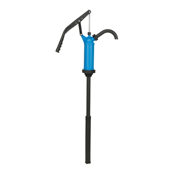
PP (polypropylene) PUMP
Lever Action
Blue
10 oz / Stroke
140° F 160° C
1-½" & 2"
PP, Steel, Polyethylene (PE)
1,000 SSU
Diesel, Kerosene, Lubricant
PPS (polyphenylene sulfide) PUMP
Lever Action
Black
10 oz / Stroke
140° F 160° C
1-½" & 2"
PPS, SS304, SS316, PTFE, PVDF
1,000 SSU
Gasoline, Diesel, Kerosene, Lubricant, Water,
Alcohol, Acids, Alkali, Solvents, Chemicals
Advertisement

Subscribe to Our Youtube Channel
Related Manuals for Pressol 13003


Summary of Contents for Pressol 13003
- Page 1 Installation and operating instructions IMPORTANT: READ BEFORE USING Technical data PP (polypropylene) PUMP PPS (polyphenylene sulfide) PUMP Pump Type Lever Action Lever Action Pump Body #1 Color Blue Black Max. Flow 10 oz / Stroke 10 oz / Stroke Max. Fluid Temperature 140°...
- Page 2 Regularly check pump and suction tubes for leaks. Leaks in the suction line or in pump housing will cause inefficient pumping and loss of prime. Pressol Schmiergeräte GmbH Parkstraße 7 93167 Falkenstein | Germany Tel. +49 9462 17-0 Fax +49 9462 17-208 info@pressol.com...
Need help?
Do you have a question about the 13003 and is the answer not in the manual?
Questions and answers