Table of Contents
Advertisement
Quick Links
Advertisement
Table of Contents

Subscribe to Our Youtube Channel
Related Manuals for PowerBox Systems Sensor V3


Summary of Contents for PowerBox Systems Sensor V3
- Page 1 Instruction Manual SEnsor...
-
Page 2: Product Description
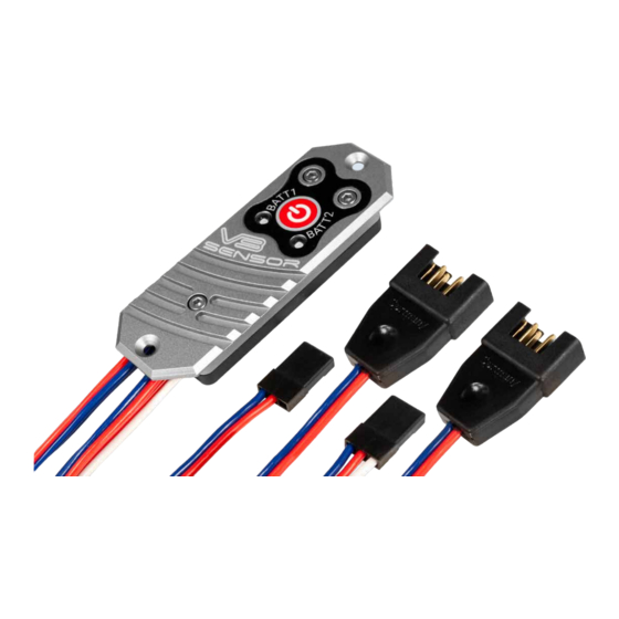
PowerBox Sensor V3 is around 35 % higher. In fact, the peak load capacity is twice as high: the Sensor V3 can handle more than 20 A for several seconds! The Sensor V3 offers two user-selectable output voltages: for normal servos it can be set to a regulated 6.0 V, while a regulated 7.8 V is available for HV servos–... - Page 3 Power to the unit can be drawn from four different battery types: LiPo, LiIon, LiFePo, NiMH. Ultra-bright RGB LEDs are fitted to indicate battery voltage; they light up in various colours to display the charge status of the batteries. CORE users also benefit from one special additional feature: both battery voltages can be displayed directly on the transmitter by means of telemetry.
-
Page 4: Features And Connections
2. INSTALLING AND CONNECTING THE BATTERIES The PowerBox Sensor V3 should be installed in the model in a position where vibration levels are low. Solid GRP fuselage sides in a power model should be fitted with an internal 3 – 4 mm thick plywood plate to minimise vibration, and to provide ‘meat’... - Page 5 For all systems except the CORE the two outputs can be considered to be identical. If your receiver only has one battery input, simply connect one of the Sensor V3’s outputs to the receiver’s battery input, and the other to any vacant servo output socket.
-
Page 6: Switching On And Off
3. SWITCHING ON AND OFF In contrast to its predecessor, the Sensor V3 only has one button, and this simpli- fies the procedure for switching on and off. As with other PowerBox devices with a single button, the sequence is as follows: Hold the button pressed in for one or two seconds until the LEDs light up violet. -
Page 7: Setting The Output Voltage
0 – 20 % 5. SETTING THE OUTPUT VOLTAGE The PowerBox Sensor V3 can be set to either of two output voltages: 6.0 V for conventional servos, and 7.8 V for HV servos. If you opt for the higher setting, please ensure that all the components connected to the system are approved for high-voltage use. - Page 8 - with the model on the ground – for about thirty seconds. If the Sensor V3 becomes hot to the touch (more than 60°C), first check that the servos, pushrods and linkages are in good order.
-
Page 9: Specification
6. REGULATOR ERRORS The unit constantly monitors the operation of the voltage regulators. If the output voltage strays outside the correct value, the LEDs indicate this by lighting up violet and flashing rapidly. Regulator errors typically occur when a battery is connected with reversed polarity. - Page 10 8. DIMENSIONS PowerBox-Systems − World Leaders in RC Power Supply Systems...
-
Page 11: Set Contents
9. SET CONTENTS - PowerBox Sensor V3 - 2x retaining screws - Operating instructions in English and German 10. SERVICE NOTE We make every effort to provide a good service to our customers, and have now established a Support Forum which covers all queries relating to our products. This helps us considerably, as we no longer have to answer frequently asked questions again and again. -
Page 12: Guarantee Conditions
11. GUARANTEE CONDITIONS At PowerBox-Systems we insist on the highest possible quality standards in the development and manufacture of our products. They are guaranteed “Made in Germany”! That is why we are able to grant a 24 month guarantee on our PowerBox Sensor V3 from the initial date of purchase. -
Page 13: Liability Exclusion
For this reason we deny liability for loss, damage or costs which arise due to the use or operation of the PowerBox Sensor V3, or which are connected with such use in any way. Regardless of the legal arguments employed, our obligation to pay compensation is limited to the invoice total of our products which were involved in the event, insofar as this is deemed legally permissible. - Page 14 12/2020 PowerBox-Systems GmbH Ludwig-Auer-Straße 5 D-86609 Donauwoerth Germany +49-906-99 99 9-200 +49-906-99 99 9-209 www.powerbox-systems.com...
Need help?
Do you have a question about the Sensor V3 and is the answer not in the manual?
Questions and answers