Advertisement
Table of Contents
- 1 Power Supply Details
- 2 Battery Charger
- 3 Control Panel Details
- 4 Mains Supply
- 5 Fresh Water
- 6 Waste Water
- 7 Battery Current
- 8 Water Tank Fill
- 9 Clock Set
- 10 Set Event Timer
- 11 Vehicle Battery
- 12 Engine Started
- 13 Operational & Safety Information
- 14 Declaration of Conformity
- 15 Electrical Connection
- Download this manual
1
Template
Instructions
<<Delete before
use>>
1 Key Features
·
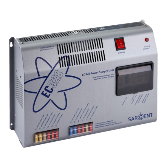
Battery Charger / Power Supply – Incorporates an air cooled 300 Watt multi-stage power converter
unit that charges the batteries and provides 12V DC power.
·
Built-in dual Solar Regulator - Allows the direct connection of a 20 to 120W solar panel
without the need for additional components. The dual regulator charges both the vehicle and
leisure batteries simultaneously.
·
Enhanced Digital Control Panel - With scrolling menu system, battery condition (voltage and
current), water tank levels, tank and battery level warnings with battery protect circuit, alarm
clock and programmable event timer.
2 System Overview
The following diagram shows the typical configuration of the EC328 system. The key component is
the EC328 power supply unit (PSU), which is the hub of the system and provides connectivity to the
ancillary components and the EC328 digital control panel.
Issue 01
EC328 Power Control System
Page 1 of 15
June 2011
Advertisement
Table of Contents

Related Manuals for Sargent EC328


Summary of Contents for Sargent EC328
- Page 1 The following diagram shows the typical configuration of the EC328 system. The key component is the EC328 power supply unit (PSU), which is the hub of the system and provides connectivity to the ancillary components and the EC328 digital control panel.
-
Page 2: Power Supply Details
Template Instructions EC328 Power Control System <<Delete before use>> 3 Power Supply Details For the safe operation of all electrical equipment within your Leisure Vehicle it is important that you read and fully understand these instructions. If you are unsure of any point please contact your dealer/distributor for advice before use. -
Page 3: Battery Charger
PSU via a dedicated connector on the base of the unit (see section 6.5 for connector details). A connection harness is available from your dealer or the Sargent web site. 3.4 Fuses WARNING When replacing fuses always replace a fuse with the correct value. - Page 4 To prevent over discharge, the EC328 system incorporates a battery protect circuit that warns and then disconnects the batteries when they fall below the following conditions:...
-
Page 5: Control Panel Details
Template Instructions EC328 Power Control System <<Delete before use>> Voltage Battery Action after cut off Notes cut off Battery selection is This cut off level is designed to protect the vehicle changed from Vehicle battery from over discharge. The 10.9v level... -
Page 6: Mains Supply
Template Instructions EC328 Power Control System <<Delete before use>> Item Function Options / Notes Use to turn the water pump(s) power on and The adjacent LED is illuminated when Pump ON/ OFF off (see section 4.3) the pump power is ON. -
Page 7: Fresh Water
Template Instructions EC328 Power Control System <<Delete before use>> Display Description Options / Notes Gel batteries if required (see section 3.7A for details) Water level in the fresh water tank 0% < ¼ Full (Nearly empty) Fresh Water (5 measurement levels) 25% >= ¼... -
Page 8: Water Tank Fill
Template Instructions EC328 Power Control System <<Delete before use>> 4.3 Menu Functions - Settings section Display Description Options / Notes Shows the currently selected pump <INTERNAL> = The internal Pump Select? that will be operated by pressing the pump will be operated by the <Internal>... -
Page 9: Set Event Timer
Template Instructions EC328 Power Control System <<Delete before use>> Display Description Options / Notes Access to set the event timer Please note the event timer Set Event Timer? uses a 24 hour cycle Press the select button (◄) to select HOUR ON... -
Page 10: Vehicle Battery
Template Instructions EC328 Power Control System <<Delete before use>> 4.5 Warning Messages This WARNING display indicates that the You can switch over to the Vehicle Battery Vehicle battery voltage is low (10.9 volts or Leisure battery immediately Dangerously Low less). The panel will beep for one minute and... - Page 11 Template Instructions EC328 Power Control System <<Delete before use>> 5.2 Common Fault Table Fault Possible Cause Proposed Fix Connecting lead between Check and connect lead as per 5.1C the site and Leisure Check also input connector at the base of the EC328PSU...
- Page 12 Other fault Contact your Dealer Fuse blown Replace fuse Turn pump on by pressing the pump button at the EC328 control Pump turned off panel (tap symbol) Pump not Both the internal and external pump feeds are controlled from the working EC328 control panel.
-
Page 13: Declaration Of Conformity
Template Instructions EC328 Power Control System <<Delete before use>> 6 Technical Data & Approvals 6.1 Outline Specification INPUT 230v 230 Volts / 0 to 16 Amps + / - 10% RCD protected, 3 x MCB outputs of 10, 10 and 6A via 2 x... -
Page 14: Electrical Connection
Template Instructions EC328 Power Control System <<Delete before use>> 6.5 Electrical Connection A) Battery Input Connector Function Fuse Wire Colour Leisure battery input 1 BROWN / BLUE Vehicle battery input 1 BROWN / GREEN Battery common earth 1 WHITE / ORANGE... - Page 15 Template Instructions EC328 Power Control System <<Delete before use>> D) 12v Output Connector Function Fuse Wire Colour Ignitions YELLOW / GREEN Not Used Radio / Entertainment BROWN / YELLOW Internal Pump GREEN / BLUE External Pump GREEN / WHITE Rear Lights 1...
Need help?
Do you have a question about the EC328 and is the answer not in the manual?
Questions and answers
Adding extra 12volt DC to DC charging So would that be connected directly to the 100 amp/hr leisure battery ? If not where to connect ?
To connect a 12V DC to DC charger to a Sargent EC328 leisure battery system:
1. Disconnect Power: Turn off the EC328 charger switch and disconnect the 230V mains supply.
2. Battery Access: Locate the leisure batteries, which may be connected in parallel. Ensure both batteries are identical if there are two.
3. Inline Fuse: Ensure an inline fuse (max 20A per battery, total not exceeding 40A) is fitted between the battery and the electrical harness.
4. Charger Connection:
- Connect the output of the DC to DC charger to the leisure battery terminals.
- Observe correct polarity: red to positive (+), black to negative (−).
- Do not use crocodile clips; use secure, bolted connections.
5. Safety: Ensure no flames or sparks near the battery, as explosive gases may be present.
6. Operation: Once connected, the charger will supply power based on load priority. The EC328 system allows up to 25A (300W) for leisure equipment, with remaining current going to battery charging.
This setup ensures the DC to DC charger works properly with the EC328 battery system.
This answer is automatically generated
Fridge and outside step not working