
Related Manuals for Electrolux Professional IB42310


Summary of Contents for Electrolux Professional IB42310
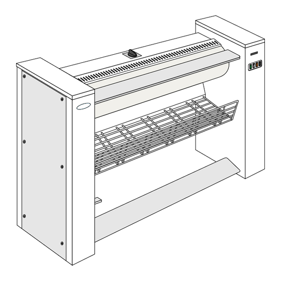
- Page 1 Installation manual Ironers IB42310 – IB42314 – IB42316 Originals instructions 05405004/EN...
-
Page 3: Table Of Contents
Contents Contents 1 Environmental information ........................5 2 Preliminary instructions........................5 3 Note about the A.C. power ........................6 4 Packaging-Weight ..........................6 5 Technical characteristics ........................7 6 Sound level............................9 7 Installation ............................10 8 Working place lighting........................11 9 Electrical connection..........................12 10 Check before use ..........................15 11 Disconnecting the machine ........................17 12 Releasing process to follow in case of connection while the bed is in back position.........17 13 Safety thermostat’s adjustment......................18... -
Page 5: Environmental Information
Installation manual 1 Environmental information Concerned by providing the end user with useful and necessary environmental information, we wish to precise: • Data about energetic consumptions, wastes (atmospheric and liquid) and sound level are indicated in the para- graph «Technical characteristics». •... -
Page 6: Note About The A.c. Power
Installation manual 3 Note about the A.C. power According to the EN 60204-1:1997 standard, the machine is provided for A.C. supplies corresponding to the ex- tracted characteristics below : 4.3.2 A.C. supplies Voltage: Steady state voltage: from 0.9 to 1.1 of nominal voltage. Frequency: from 0.99 to 1.01 of nominal frequency continuously. -
Page 7: Technical Characteristics
Installation manual 5 Technical characteristics Neither base nor sealing are indispensable. It is yet possible to fix the ironer to the floor. To do so, use the holes made to block the machine on the transport pallet. - Page 8 Installation manual Ironing width Units 1.4 m 1.6 m Overall length 1395 1795 2045 Length of feeding table 1000 1400 1650 Cylinder diameter 1220 1620 1870 Distance between feet Evacuation diameter nothing 36/40 36/40 Electrical connection see table see table see table Main voltage see table...
-
Page 9: Sound Level
Installation manual Ironing Supply voltage Rated intensity Main switch Connection cable Fuse width section 400/415 V 3+N+E ~ 50/60 Hz 7.4 A 4 x 20 A 5 x 2.5 mm² 10 A 400/415 V 3+E ~ 50/60 Hz 7.4 A 3 x 20 A 4x 2.5 mm²... -
Page 10: Installation
Installation manual Important This ironing machine should only be used for previously washed and pre-dried, machine-ironable textiles. Important In this normal case of use, it is not necessary to connect the exhaust duct to the open air. In the opposite case, the exhaust duct must be connected to the open air, by the shortest way, and with as few bents as possible. -
Page 11: Working Place Lighting
Installation manual Remove the 2 fixing screws (1 screw by casing) which fix the machine to the transport pallet and unload the machine. Install the ironer in an area where it is easily accessible by both operators and service technicians. Make sure that the side of the machine is at least 100 cm away from walls or other machines. -
Page 12: Electrical Connection
Installation manual The average lighting value on the working place recommended by the clothing industry for inspecting linen is 500 lux. Whenever possible, the working place should be illuminated by daylight. 9 Electrical connection Prior to use, the machine should be plugged into a correctly earthed power socket complying with the standard in force. - Page 13 Installation manual Three-phase connection 3 AC + E (PE) Connect the machine’s power cable to the terminal block on the printed circuit provided for the purpose. Phase no 1 Phase no 2 Phase no 3 Earth connection Control fuse to protect the electrical control circuit (1.25 A) Single-phase connection 1N AC + E (PE) Connect the machine’s power cable to the terminal block on the printed circuit provided for the purpose.
- Page 14 Installation manual Mains transformer connection diagrams according to the customer’s various mains voltage (machines pro- vided with a transformer only). 400 Volts supply Measure the mains voltage at the primary with a volt- meter between 0 and 400 volts of the transformer. If the voltage is equal to 400 volts, do not touch the transformer connection which should be as indicated in the margin.
-
Page 15: Check Before Use
Installation manual Important Once connected, make sure to check the correct order of phase connections. Caution If the phases are not connected the right order, when switching on the machine, the bed remains in contact against the cylinder, this last rotates clockwise (see from the machine right side), but the safety hand device is inoperative. - Page 16 Installation manual Important The control pedal must not be operated before making the following checks. If the functioning of the machine does not correspond to either case (A) or (B), stop the machine with the On/Off switch, put the main switch to Off and invert the 2 phase wires on the power supply terminal block. (A) Phases in good order and bed closed (B) Phases in good order and bed opened When starting up the ironer, the cylinder does not rotate and the bed...
-
Page 17: Disconnecting The Machine
Installation manual 11 Disconnecting the machine Important If you wish to disconnect the electrical supply cable, it is more wise to do it once the machine id cooled down and to stop the ironer with the bed contact with the cylinder. Proceed as follows: •... -
Page 18: Safety Thermostat's Adjustment
Installation manual 13 Safety thermostat’s adjustment Important This ironer has an adjustable safety thermostat in order to avoid damages of the cotton covering in case of ma- chine stop with the bed closed. This safety thermostat is adjusted in our plant so that the regulation thermostat doesn’t go above the temperature corresponding to the position ••... -
Page 19: Star / Triangle Commutation Diagram
Installation manual Important Check-out Before leaving, put the appliance into operation and allow to run a complete cycle. Watch to ensure that all burner system components function correctly. 14 Star / Triangle Commutation diagram Heating resistor commutation Motion motor commutation “Star”... -
Page 20: Annexes
Installation manual 15 Annexes 15.1 Control diagram printed circuit... -
Page 21: Component Implantation Printed Circuit
Installation manual 15.2 Component implantation printed circuit PLASTRON = PANEL CONTROL BARRE = BAR CUV. = BED MONNAYEUR = COIN OPERATING SYSTEM MOTEUR = MOTOR CHAUFFAGE = HEATING VENT. = VENTILATEUR PEDALE = PEDAL... -
Page 22: Conversion Of Measurement Units
Installation manual 16 Conversion of measurement units This following is a list of correspondences of the main frequency used units, to avoid the need to use measurement unit conversion table. 1 bar = 100 000 Pa British thermal unit 1 Btu = 1 055.06 J 1 bar = 1.019 7 kg/cm²... - Page 24 Share more of our thinking at www.electroluxprofessional.com...
Need help?
Do you have a question about the IB42310 and is the answer not in the manual?
Questions and answers